RENAULT KANGOO 1997 KC / 1.G Foult Finding - Injection Service Manual
Manufacturer: RENAULT, Model Year: 1997, Model line: KANGOO, Model: RENAULT KANGOO 1997 KC / 1.GPages: 363
Page 41 of 363
DPCF01 1.0
LUCAS DIESEL INJECTION
Fault finding - Customer complaints
13
Only consult these customer complaints after a complete check using the XR25.NOTES
No dialogue from the computer to the XR25.
Idle speed too high (when air conditioning not requested)
No fast idle when air conditioning requested
Starting fault (engine will not start or is difficult to start).
Warning light illuminates with no fault shown by the XR25.
Vehicle produces black smoke at altitude
Chart 1
Chart 2
Chart 3
Chart 4
Chart 5
Chart 6
13-37
Page 42 of 363
DPCF01 1.0
LUCAS DIESEL INJECTION
Fault finding - Fault charts
13
AFTER REPAIR
Use bornier Elé. 1332 for any operations on the computer connector.NOTES
Chart 1NO DIALOGUE FROM THE COMPUTER TO THE XR25.
Ensure that the XR25 is not the cause of the fault by trying to communicate with the computer on ano-
ther vehicle. If the XR25 is not the cause of the fault and dialogue is not established with another compu-
ter on the same vehicle, a faulty computer may be causing interference on the K and L fault finding lines.
Disconnect connections successively to determine which computer is at fault.
Check the ISO selector is on position S8, that you are using the latest XR25 cassette and the correct access
code (D34).
Check the battery voltage and carry out any necessary operations to ensure the correct voltage (U battery
> 10.5 volts).
Carry out a road test then check using the XR25.
Deal with any illuminated fault bargraphs.
Check the 15 Amp fuses on the engine connection unit have not blown (positions 3 and 4).
Check the connection and condition of the connections on the computer connector and the connection
R67 engine / dashboard.
Check the computer is correctly fed:
- Earth on track 2 of the computer connector (check the condition and tightness of the engine earth
strap and the engine earth on the gearbox housing).
- + after ignition feed on track 1 of the computer connector.
Check the diagnostic socket is correctly fed:
- Earth on track 5.
- + before ignition feed on track 16.
Check and ensure the continuity and insulation of the lines in the connection diagnostic socket/
computer:
- Between track 10 of the computer connector and track 15 of the diagnostic socket.
- Between track 13 of the computer connector and track 7 of the diagnostic socket.
If fault finding is not established after these operations, replace the computer (consult the "Aid" section
for this operation).
13-38
Page 43 of 363
DPCF01 1.0
LUCAS DIESEL INJECTION
Fault finding - Fault charts
13
Carry out a road test then check using the XR25.AFTER REPAIR
Only consult this customer complaint after a complete check using the XR25.NOTES
Chart 2IDLE SPEED TOO HIGH (WHEN AIR CONDITIONING NOT
REQUESTED)
This fault may be connected to fast idle operation.
Check the condition of the pneumatic circuit for the fast idle solenoid valve.
Look for a short circuit to + 12 volts of the connection between track 11 on the injection computer and
track 20 on the BE connector for the air conditioning computer ("AC Inj. / fast idle" information).
13-39
Page 44 of 363
DPCF01 1.0
LUCAS DIESEL INJECTION
Fault finding - Fault charts
13
Carry out a road test then check using the XR25.AFTER REPAIR
NOTES
Chart 3NO FAST IDLE WHEN AIR CONDITIONING REQUESTED
Only consult this customer complaint after a complete check using the XR25.
Look for an open circuit or a short circuit to earth on the connection between track 11 on the injection
computer and track 20 on the BE connector for the air conditioning computer ("AC Inj. / fast idle" infor-
mation).
This fault causes the absence of illumination of bargraph 9 LH side "air conditioning requested".
13-40
Page 45 of 363
DPCF01 1.0
LUCAS DIESEL INJECTION
Fault finding - Fault charts
13
Carry out a road test then check using the XR25.AFTER REPAIR
If the fault persists, check the fuel supply circuits (for the pump and the injectors).
If necessary, carry out a complete check of the engine (starter drive speed, pump timing, condition of
injectors, rocker arm clearances, compression, .....).NOTES
Chart 4STARTING FAULT (ENGINE WILL NOT START OR IS DIFFICULT TO
START) (warning light extinguished).
Only consult this customer complaint after a complete check using the XR25.
If no fault is shown by the XR25, ensure that the fault is not caused by a faulty immobiliser system.
Check the operation of the preheating system:
Start command mode G10*1* and check for a voltage at the plugs.
If the plugs are not fed, check the connection of the 3 track connector on the relay unit and the condition
of the 70 Amp fuse on the engine connection unit.
13-41
Page 46 of 363
DPCF01 1.0
LUCAS DIESEL INJECTION
Fault finding - Fault charts
13
Carry out a road test then check using the XR25.AFTER REPAIR
NOTES
Chart 5WARNING LIGHT ILLUMINATES WITH NO FAULT SHOWN BY THE
XR25.
Only consult this customer complaint after a complete check using the XR25.
If no fault is shown by the XR25, look for a short circuit to earth of the heater plug feed wiring or a plug
short circuit fault.
13-42
Page 47 of 363
DPCF01 1.0
LUCAS DIESEL INJECTION
Fault finding - Fault charts
13
Carry out a road test then check using the XR25.AFTER REPAIR
NOTES
Chart 6VEHICLE PRODUCES BLACK SMOKE AT ALTITUDE
Only consult this customer complaint after a complete check using the XR25.
Measure the resistance of the altimetric corrector at the 10 track pump connector (between tracks 1 and
6).
Replace the altimetric corrector if the resistance is not approximately 15 ohms.
Ensure the continuity of the connection between track 1 on the pump connector, wiring side, and track 5
on the altimetric connector control relay (position H on the relay plate in the engine connection unit).
Ensure the presence of earth on track 6 of the pump connector, wiring side.
13-43
Page 48 of 363

E7J 780 ENGINE
MULTIPOINT INJECTION
FAULT FINDING
CONTENTS
Introduction . . . . . . . . . . . . . . . . . . . . . . . . . . . . . . . . . . . . . . . . . . . . . . . . . . . . . . . . . . . . . . . . . . . . . . . . . . . . . . . . . 01
XR25 fiche . . . . . . . . . . . . . . . . . . . . . . . . . . . . . . . . . . . . . . . . . . . . . . . . . . . . . . . . . . . . . . . . . . . . . . . . . . . . . . . . . . . 06
Interpretation of XR25 bargraphs . . . . . . . . . . . . . . . . . . . . . . . . . . . . . . . . . . . . . . . . . . . . . . . . . . . . . . . . . . . . . . 09
Status and parameter checks . . . . . . . . . . . . . . . . . . . . . . . . . . . . . . . . . . . . . . . . . . . . . . . . . . . . . . . . . . . . . . . . . . 30
Status and parameter interpretation . . . . . . . . . . . . . . . . . . . . . . . . . . . . . . . . . . . . . . . . . . . . . . . . . . . . . . . . . . . 36
Customer complaints . . . . . . . . . . . . . . . . . . . . . . . . . . . . . . . . . . . . . . . . . . . . . . . . . . . . . . . . . . . . . . . . . . . . . . . . . 56
Fault charts . . . . . . . . . . . . . . . . . . . . . . . . . . . . . . . . . . . . . . . . . . . . . . . . . . . . . . . . . . . . . . . . . . . . . . . . . . . . . . . . . . 57
Aid . . . . . . . . . . . . . . . . . . . . . . . . . . . . . . . . . . . . . . . . . . . . . . . . . . . . . . . . . . . . . . . . . . . . . . . . . . . . . . . . . . . . . . . . . 62
Checking conformity . . . . . . . . . . . . . . . . . . . . . . . . . . . . . . . . . . . . . . . . . . . . . . . . . . . . . . . . . . . . . . . . . . . . . . . . . 63Page
Page 49 of 363
JF5111.0
INJECTION
Fault finding- Introduction
17
E7J 780
engine
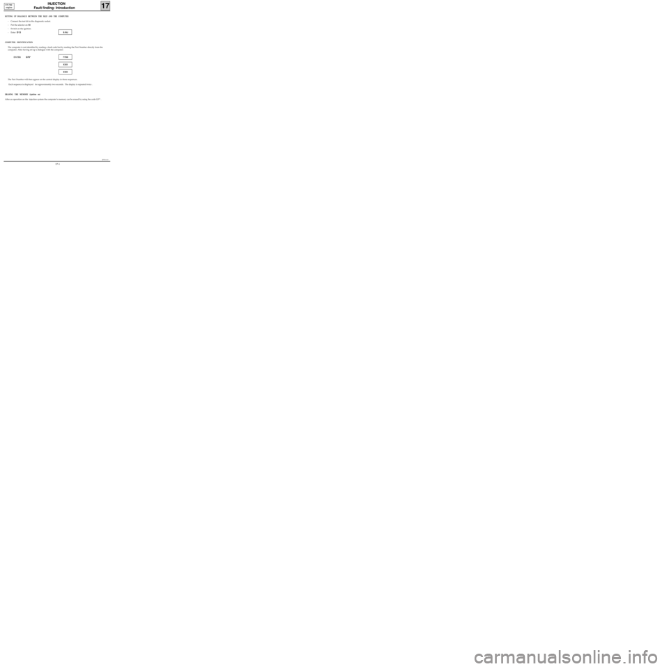
SETTING UP DIALOGUE BETWEEN THE XR25 AND THE COMPUTER
- Connect the test kit to the diagnostic socket.
- Put the selector on S8
- Switch on the ignition.
- Enter D13 9.NJ
COMPUTER IDENTIFICATION
The computer is not identified by reading a fault code but by reading the Part Number directly from the
computer. After having set up a dialogue with the computer:
ENTER G70*7700
XXX
XXX
The Part Number will then appear on the central display in three sequences.
Each sequence is displayed for approximately two seconds. The display is repeated twice .
ERASING THE MEMORY (ignition on)
After an operation on the injection system the computer’s memory can be erased by using the code G0** .
17-1
Page 50 of 363
JF5111.0
INJECTION
Fault finding - Introduction
17
E7J 780
engine
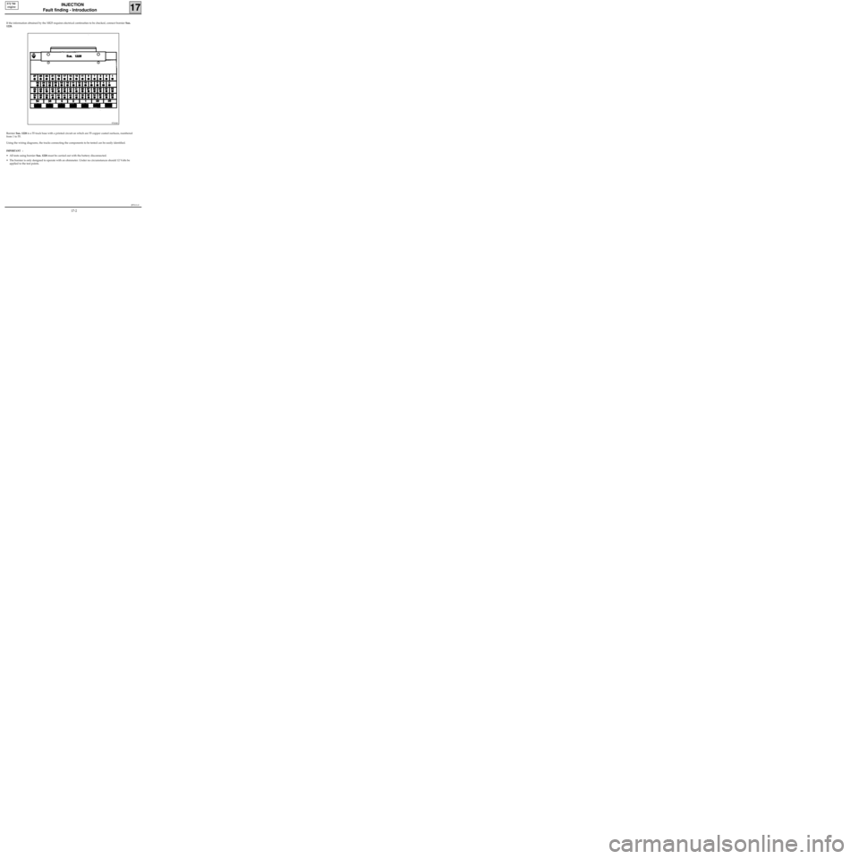
If the information obtained by the XR25 requires electrical continuities to be checked, connect bornier Sus.
1228.
Bornier Sus. 1228 is a 55 track base with a printed circuit on which are 55 copper coated surfaces, numbered
from 1 to 55.
Using the wiring diagrams, the tracks connecting the components to be tested can be easily identified.
IMPORTANT :
• All tests using bornier Sus. 1228 must be carried out with the battery disconnected.
• The bornier is only designed to operate with an ohmmeter. Under no circumstances should 12 Volts be
applied to the test points.
97434S
17-2