RENAULT KANGOO 2013 X61 / 2.G Diesel DCM 1.2 Injection Service Manual
Manufacturer: RENAULT, Model Year: 2013, Model line: KANGOO, Model: RENAULT KANGOO 2013 X61 / 2.GPages: 204, PDF Size: 0.99 MB
Page 41 of 204
13B-41
AFTER REPAIRDeal with any faults declared by the diagnostic tool.
Clear the computer memory.
Carry out a road test followed by another check with the diagnostic tool.
V1 MR-376-X76-13B000$071.mif
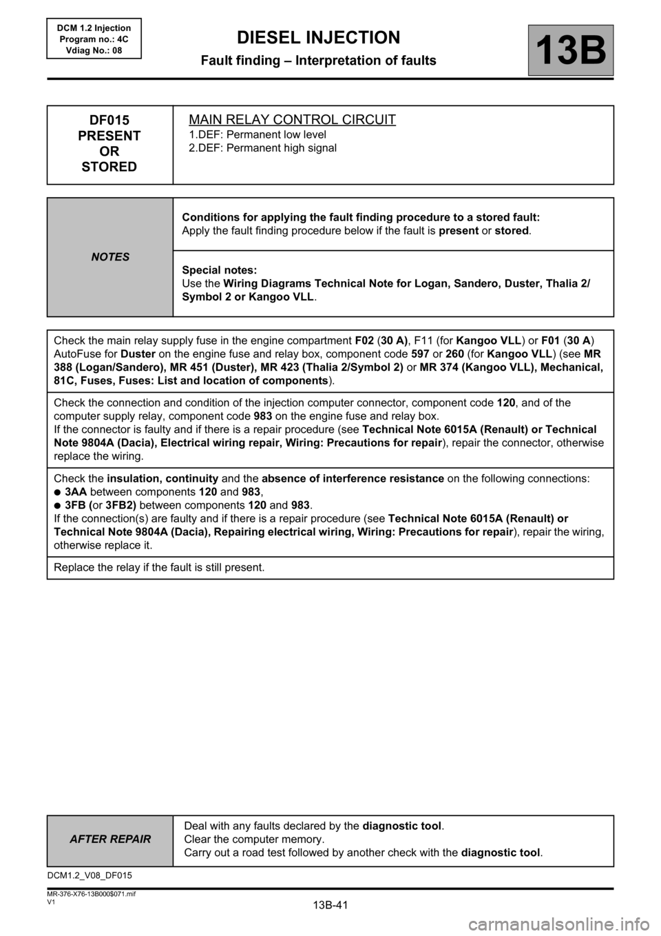
DIESEL INJECTION
Fault finding – Interpretation of faults13B
DCM 1.2 Injection
Program no.: 4C
Vdiag No.: 08
DF015
PRESENT
OR
STOREDMAIN RELAY CONTROL CIRCUIT
1.DEF: Permanent low level
2.DEF: Permanent high signal
NOTESConditions for applying the fault finding procedure to a stored fault:
Apply the fault finding procedure below if the fault is present or stored.
Special notes:
Use the Wiring Diagrams Technical Note for Logan, Sandero, Duster, Thalia 2/
Symbol 2 or Kangoo VLL.
Check the main relay supply fuse in the engine compartment F02 (30 A), F11 (for Kangoo VLL) or F01 (30 A)
AutoFuse for Duster on the engine fuse and relay box, component code 597 or 260 (for Kangoo VLL) (see MR
388 (Logan/Sandero), MR 451 (Duster), MR 423 (Thalia 2/Symbol 2) or MR 374 (Kangoo VLL), Mechanical,
81C, Fuses, Fuses: List and location of components).
Check the connection and condition of the injection computer connector, component code 120, and of the
computer supply relay, component code 983 on the engine fuse and relay box.
If the connector is faulty and if there is a repair procedure (see Technical Note 6015A (Renault) or Technical
Note 9804A (Dacia), Electrical wiring repair, Wiring: Precautions for repair), repair the connector, otherwise
replace the wiring.
Check the insulation, continuity and the absence of interference resistance on the following connections:
●3AA between components 120 and 983,
●3FB (or 3FB2) between components 120 and 983.
If the connection(s) are faulty and if there is a repair procedure (see Technical Note 6015A (Renault) or
Technical Note 9804A (Dacia), Repairing electrical wiring, Wiring: Precautions for repair), repair the wiring,
otherwise replace it.
Replace the relay if the fault is still present.
DCM1.2_V08_DF015
Page 42 of 204
13B-42
AFTER REPAIRDeal with any faults declared by the diagnostic tool.
Clear the computer memory.
Carry out a road test followed by another check with the diagnostic tool.
V1 MR-376-X76-13B000$071.mif
DIESEL INJECTION
Fault finding – Interpretation of faults13B
DCM 1.2 Injection
Program no.: 4C
Vdiag No.: 08
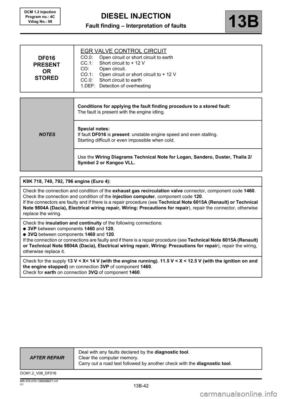
DF016
PRESENT
OR
STOREDEGR VALVE CONTROL CIRCUITCO.0: Open circuit or short circuit to earth
CC.1: Short circuit to + 12 V
CO: Open circuit.
CO.1: Open circuit or short circuit to + 12 V
CC.0: Short circuit to earth
1.DEF: Detection of overheating
NOTESConditions for applying the fault finding procedure to a stored fault:
The fault is present with the engine idling.
Special notes:
If fault DF016 is present: unstable engine speed and even stalling.
Starting difficult or even impossible when cold.
Use the Wiring Diagrams Technical Note for Logan, Sandero, Duster, Thalia 2/
Symbol 2 or Kangoo VLL.
K9K 718, 740, 792, 796 engine (Euro 4):
Check the connection and condition of the exhaust gas recirculation valve connector, component code 1460.
Check the connection and condition of the injection computer, component code 120.
If the connectors are faulty and if there is a repair procedure (see Technical Note 6015A (Renault) or Technical
Note 9804A (Dacia), Electrical wiring repair, Wiring: Precautions for repair), repair the connector, otherwise
replace the wiring.
Check the insulation and continuity of the following connections:
●3VP between components 1460 and 120,
●3VQ between components 1460 and 120.
If the connection or connections are faulty and if there is a repair procedure (see Technical Note 6015A (Renault)
or Technical Note 9804A (Dacia), Electrical wiring repair, Wiring: Precautions for repair), repair the wiring,
otherwise replace it.
Check for the supply 13 V < X< 14 V (with the engine running), 11.5 V < X < 12.5 V (with the ignition on and
the engine stopped) on connection 3VP of component 1460.
Check for earth on connection 3VQ of component 1460.
DCM1.2_V08_DF016
Page 43 of 204
13B-43
AFTER REPAIRDeal with any faults declared by the diagnostic tool.
Clear the computer memory.
Carry out a road test followed by another check with the diagnostic tool.
V1 MR-376-X76-13B000$071.mif
DIESEL INJECTION
Fault finding – Interpretation of faults13B
DCM 1.2 Injection
Program no.: 4C
Vdiag No.: 08
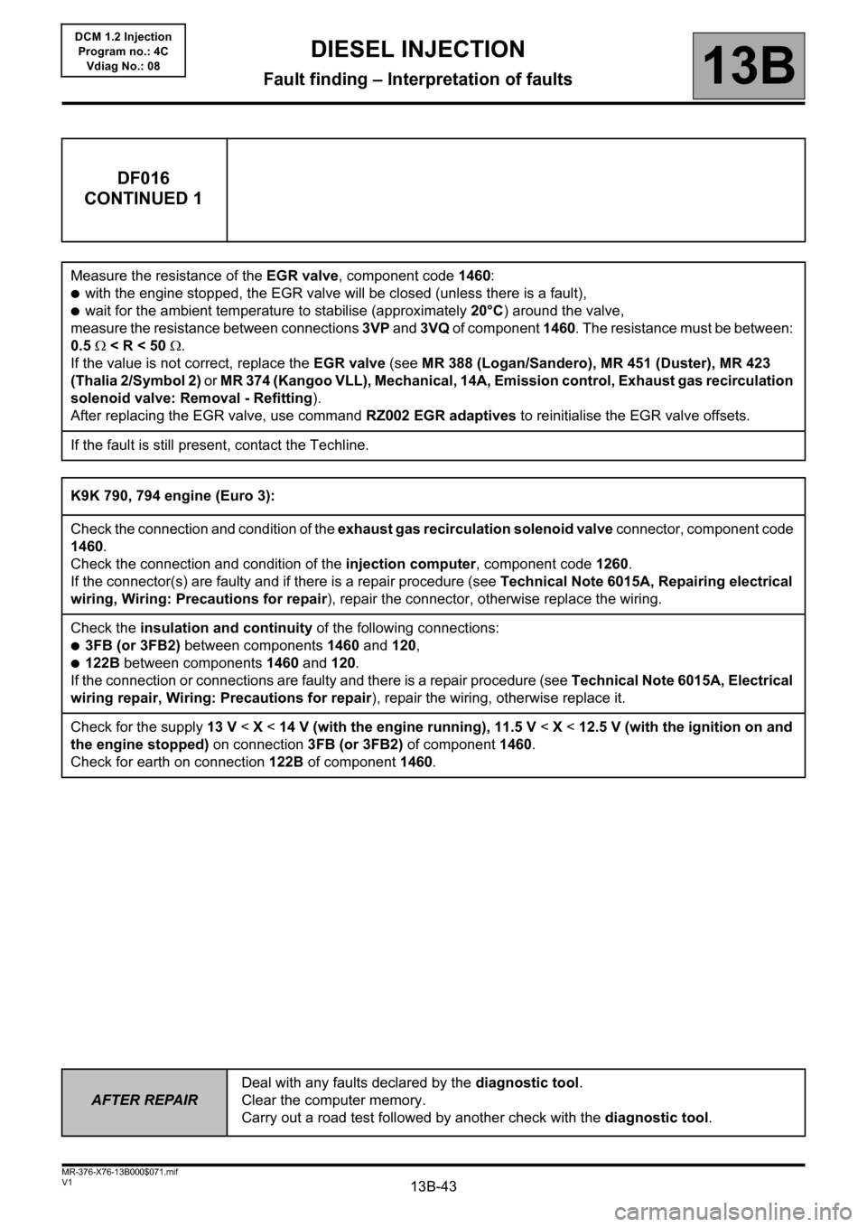
DF016
CONTINUED 1
Measure the resistance of the EGR valve, component code 1460:
●with the engine stopped, the EGR valve will be closed (unless there is a fault),
●wait for the ambient temperature to stabilise (approximately 20°C) around the valve,
measure the resistance between connections 3VP and 3VQ of component 1460. The resistance must be between:
0.5 < R < 50 .
If the value is not correct, replace the EGR valve (see MR 388 (Logan/Sandero), MR 451 (Duster), MR 423
(Thalia 2/Symbol 2) or MR 374 (Kangoo VLL), Mechanical, 14A, Emission control, Exhaust gas recirculation
solenoid valve: Removal - Refitting).
After replacing the EGR valve, use command RZ002 EGR adaptives to reinitialise the EGR valve offsets.
If the fault is still present, contact the Techline.
K9K 790, 794 engine (Euro 3):
Check the connection and condition of the exhaust gas recirculation solenoid valve connector, component code
1460.
Check the connection and condition of the injection computer, component code 1260.
If the connector(s) are faulty and if there is a repair procedure (see Technical Note 6015A, Repairing electrical
wiring, Wiring: Precautions for repair), repair the connector, otherwise replace the wiring.
Check the insulation and continuity of the following connections:
●3FB (or 3FB2) between components 1460 and 120,
●122B between components 1460 and 120.
If the connection or connections are faulty and there is a repair procedure (see Technical Note 6015A, Electrical
wiring repair, Wiring: Precautions for repair), repair the wiring, otherwise replace it.
Check for the supply 13 V < X < 14 V (with the engine running), 11.5 V < X < 12.5 V (with the ignition on and
the engine stopped) on connection 3FB (or 3FB2) of component 1460.
Check for earth on connection122B of component1460.
Page 44 of 204
13B-44
AFTER REPAIRDeal with any faults declared by the diagnostic tool.
Clear the computer memory.
Carry out a road test followed by another check with the diagnostic tool.
V1 MR-376-X76-13B000$071.mif
DIESEL INJECTION
Fault finding – Interpretation of faults13B
DCM 1.2 Injection
Program no.: 4C
Vdiag No.: 08
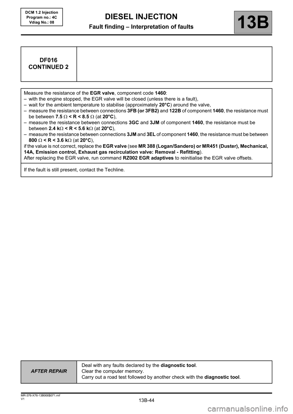
DF016
CONTINUED 2
Measure the resistance of the EGR valve, component code 1460:
– with the engine stopped, the EGR valve will be closed (unless there is a fault),
– wait for the ambient temperature to stabilise (approximately 20°C) around the valve,
– measure the resistance between connections 3FB (or 3FB2) and 122B of component 1460, the resistance must
be between 7.5 < R < 8.5 (at 20°C),
– measure the resistance between connections 3GC and 3JM of component 1460, the resistance must be
between 2.4 k < R < 5.6 k (at 20°C),
– measure the resistance between connections 3JM and 3EL of component 1460, the resistance must be between
800 < R < 3.6 k (at 20°C),
if the value is not correct, replace the EGR valve (see MR 388 (Logan/Sandero) or MR451 (Duster), Mechanical,
14A, Emission control, Exhaust gas recirculation valve: Removal - Refitting).
After replacing the EGR valve, run command RZ002 EGR adaptives to reinitialise the EGR valve offsets.
If the fault is still present, contact the Techline.
Page 45 of 204
13B-45
AFTER REPAIRDeal with any faults declared by the diagnostic tool.
Clear the computer memory.
Carry out a road test followed by another check with the diagnostic tool.
V1 MR-376-X76-13B000$071.mif
DIESEL INJECTION
Fault finding – Interpretation of faults13B
DCM 1.2 Injection
Program no.: 4C
Vdiag No.: 08
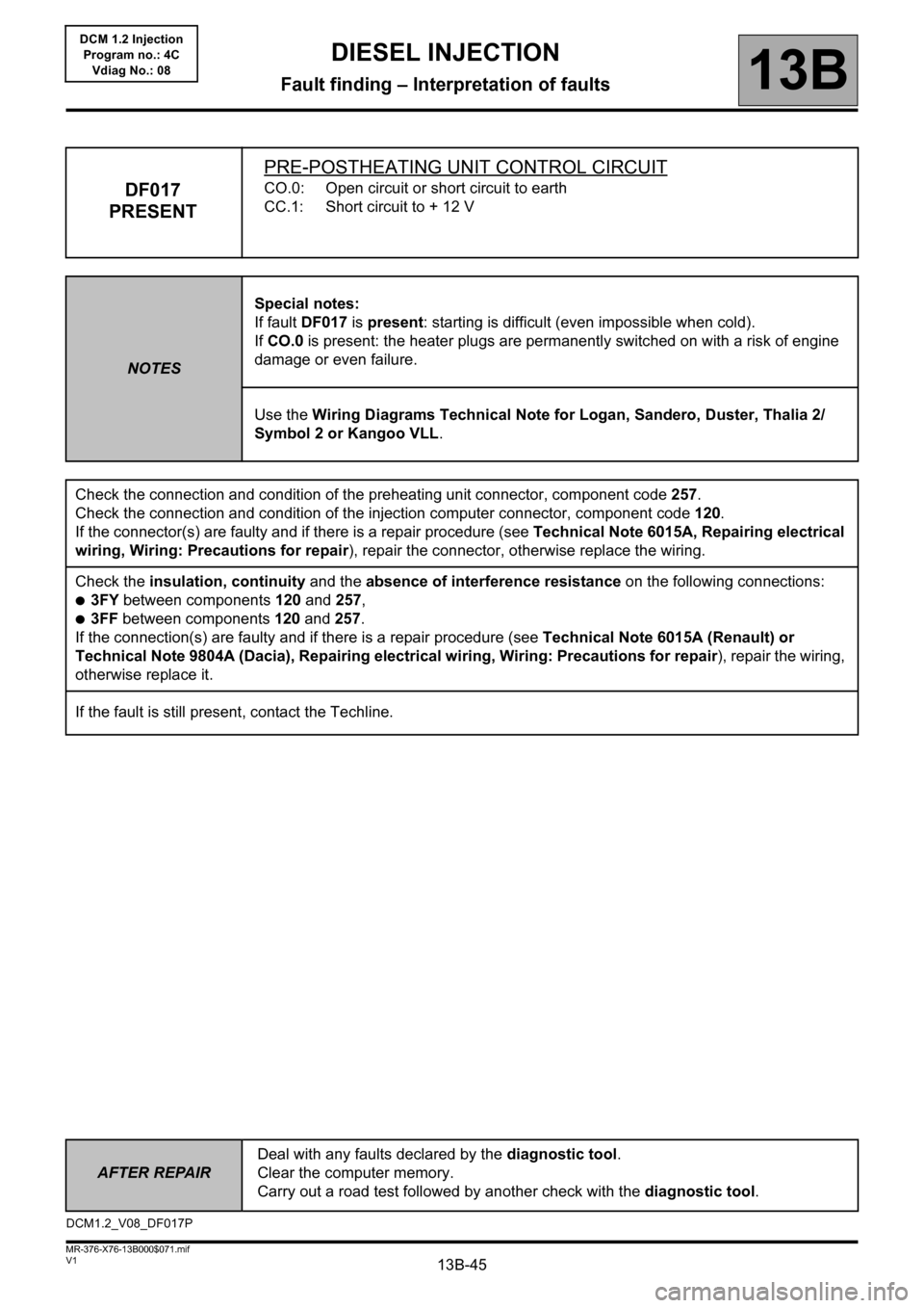
DF017
PRESENTPRE-POSTHEATING UNIT CONTROL CIRCUITCO.0: Open circuit or short circuit to earth
CC.1: Short circuit to + 12 V
NOTESSpecial notes:
If fault DF017 is present: starting is difficult (even impossible when cold).
If CO.0 is present: the heater plugs are permanently switched on with a risk of engine
damage or even failure.
Use the Wiring Diagrams Technical Note for Logan, Sandero, Duster, Thalia 2/
Symbol 2 or Kangoo VLL.
Check the connection and condition of the preheating unit connector, component code 257.
Check the connection and condition of the injection computer connector, component code 120.
If the connector(s) are faulty and if there is a repair procedure (see Technical Note 6015A, Repairing electrical
wiring, Wiring: Precautions for repair), repair the connector, otherwise replace the wiring.
Check the insulation, continuity and the absence of interference resistance on the following connections:
●3FY between components 120 and 257,
●3FF between components 120 and 257.
If the connection(s) are faulty and if there is a repair procedure (see Technical Note 6015A (Renault) or
Technical Note 9804A (Dacia), Repairing electrical wiring, Wiring: Precautions for repair), repair the wiring,
otherwise replace it.
If the fault is still present, contact the Techline.
DCM1.2_V08_DF017P
Page 46 of 204
13B-46
AFTER REPAIRDeal with any faults declared by the diagnostic tool.
Clear the computer memory.
Carry out a road test followed by another check with the diagnostic tool.
V1 MR-376-X76-13B000$071.mif
DIESEL INJECTION
Fault finding – Interpretation of faults13B
DCM 1.2 Injection
Program no.: 4C
Vdiag No.: 08
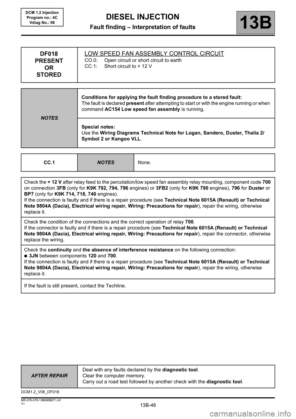
DF018
PRESENT
OR
STOREDLOW SPEED FAN ASSEMBLY CONTROL CIRCUIT
CO.0: Open circuit or short circuit to earth
CC.1: Short circuit to + 12 V
NOTESConditions for applying the fault finding procedure to a stored fault:
The fault is declared present after attempting to start or with the engine running or when
command AC154 Low speed fan assembly is running.
Special notes:
Use the Wiring Diagrams Technical Note for Logan, Sandero, Duster, Thalia 2/
Symbol 2 or Kangoo VLL.
CC.1
NOTESNone.
Check the + 12 V after relay feed to the percolation/low speed fan assembly relay mounting, component code 700
on connection 3FB (only for K9K 792, 794, 796 engines) or 3FB2 (only for K9K 790 engines), 796 for Duster or
BP7 (only for K9K 714, 718, 740 engines).
If the connection is faulty and if there is a repair procedure (see Technical Note 6015A (Renault) or Technical
Note 9804A (Dacia), Electrical wiring repair, Wiring: Precautions for repair), repair the wiring, otherwise
replace it.
Check the condition of the connections and the correct operation of relay 700.
If the connector is faulty and if there is a repair procedure (see Technical Note 6015A (Renault) or Technical
Note 9804A (Dacia), Electrical wiring repair, Wiring: Precautions for repair), repair the connector, otherwise
replace the wiring.
Check the continuity and the absence of interference resistance on the following connection:
●3JN between components 120 and 700.
If the connection is faulty and if there is a repair procedure (see Technical Note 6015A (Renault) or Technical
Note 9804A (Dacia), Electrical wiring repair, Wiring: Precautions for repair), repair the wiring, otherwise
replace it.
If the fault is still present, contact the Techline.
DCM1.2_V08_DF018
Page 47 of 204
13B-47
AFTER REPAIRDeal with any faults declared by the diagnostic tool.
Clear the computer memory.
Carry out a road test followed by another check with the diagnostic tool.
V1 MR-376-X76-13B000$071.mif
DIESEL INJECTION
Fault finding – Interpretation of faults13B
DCM 1.2 Injection
Program no.: 4C
Vdiag No.: 08
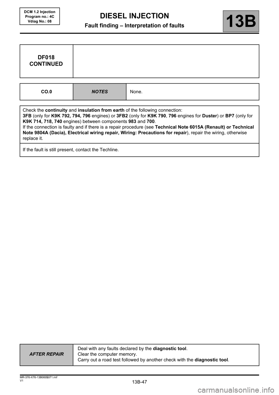
DF018
CONTINUED
CO.0NOTESNone.
Check the continuity and insulation from earth of the following connection:
3FB (only for K9K 792, 794, 796 engines) or 3FB2 (only for K9K 790, 796 engines for Duster) or BP7 (only for
K9K 714, 718, 740 engines) between components 983 and 700.
If the connection is faulty and if there is a repair procedure (see Technical Note 6015A (Renault) or Technical
Note 9804A (Dacia), Electrical wiring repair, Wiring: Precautions for repair), repair the wiring, otherwise
replace it.
If the fault is still present, contact the Techline.
Page 48 of 204
13B-48
AFTER REPAIRDeal with any faults declared by the diagnostic tool.
Clear the computer memory.
Carry out a road test followed by another check with the diagnostic tool.
V1 MR-376-X76-13B000$071.mif
DIESEL INJECTION
Fault finding – Interpretation of faults13B
DCM 1.2 Injection
Program no.: 4C
Vdiag No.: 08
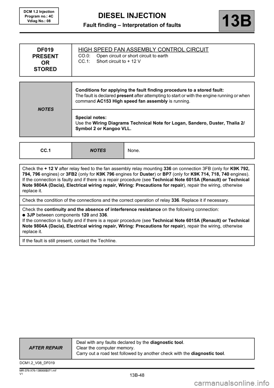
DF019
PRESENT
OR
STOREDHIGH SPEED FAN ASSEMBLY CONTROL CIRCUIT
CO.0: Open circuit or short circuit to earth
CC.1: Short circuit to + 12 V
NOTESConditions for applying the fault finding procedure to a stored fault:
The fault is declared present after attempting to start or with the engine running or when
command AC153 High speed fan assembly is running.
Special notes:
Use the Wiring Diagrams Technical Note for Logan, Sandero, Duster, Thalia 2/
Symbol 2 or Kangoo VLL.
CC.1
NOTESNone.
Check the + 12 V after relay feed to the fan assembly relay mounting 336 on connection 3FB (only for K9K 792,
794, 796 engines) or 3FB2 (only for K9K 796 engines for Duster) or BP7 (only for K9K 714, 718, 740 engines).
If the connection is faulty and if there is a repair procedure (see Technical Note 6015A (Renault) or Technical
Note 9804A (Dacia), Electrical wiring repair, Wiring: Precautions for repair), repair the wiring, otherwise
replace it.
Check the condition of the connections and the correct operation of relay 336. Replace it if necessary.
Check the continuity and the absence of interference resistance on the following connection:
●3JP between components 120 and 336.
If the connection is faulty and if there is a repair procedure (see Technical Note 6015A (Renault) or Technical
Note 9804A (Dacia), Electrical wiring repair, Wiring: Precautions for repair), repair the wiring, otherwise
replace it.
If the fault is still present, contact the Techline.
DCM1.2_V08_DF019
Page 49 of 204
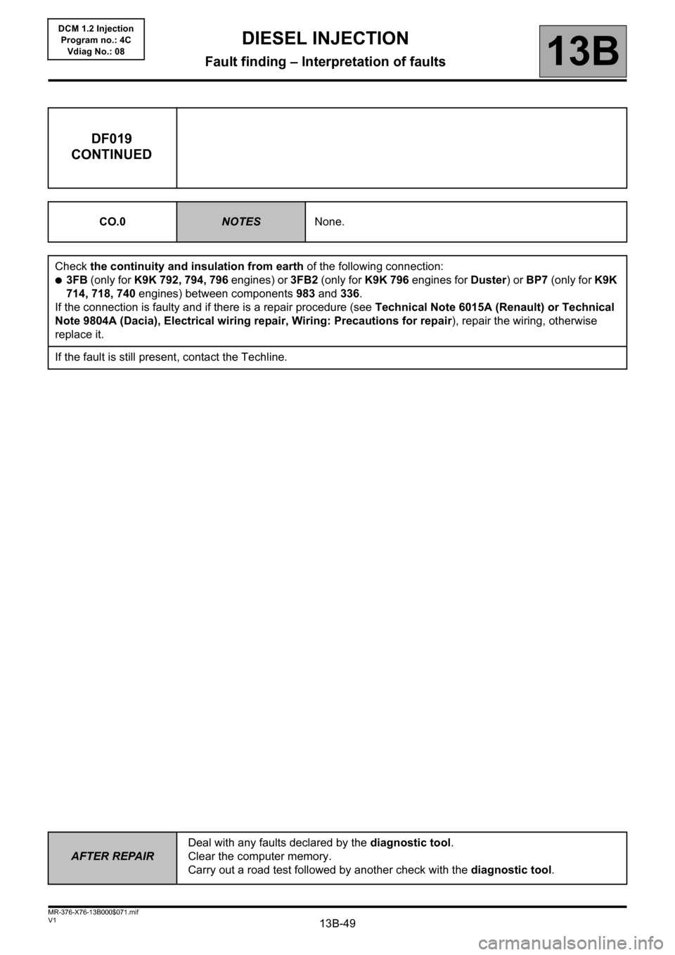
13B-49
AFTER REPAIRDeal with any faults declared by the diagnostic tool.
Clear the computer memory.
Carry out a road test followed by another check with the diagnostic tool.
V1 MR-376-X76-13B000$071.mif
DIESEL INJECTION
Fault finding – Interpretation of faults13B
DCM 1.2 Injection
Program no.: 4C
Vdiag No.: 08
DF019
CONTINUED
CO.0NOTESNone.
Check the continuity and insulation from earth of the following connection:
●3FB (only for K9K 792, 794, 796 engines) or 3FB2 (only for K9K 796 engines for Duster) or BP7 (only for K9K
714, 718, 740 engines) between components 983 and 336.
If the connection is faulty and if there is a repair procedure (see Technical Note 6015A (Renault) or Technical
Note 9804A (Dacia), Electrical wiring repair, Wiring: Precautions for repair), repair the wiring, otherwise
replace it.
If the fault is still present, contact the Techline.
Page 50 of 204
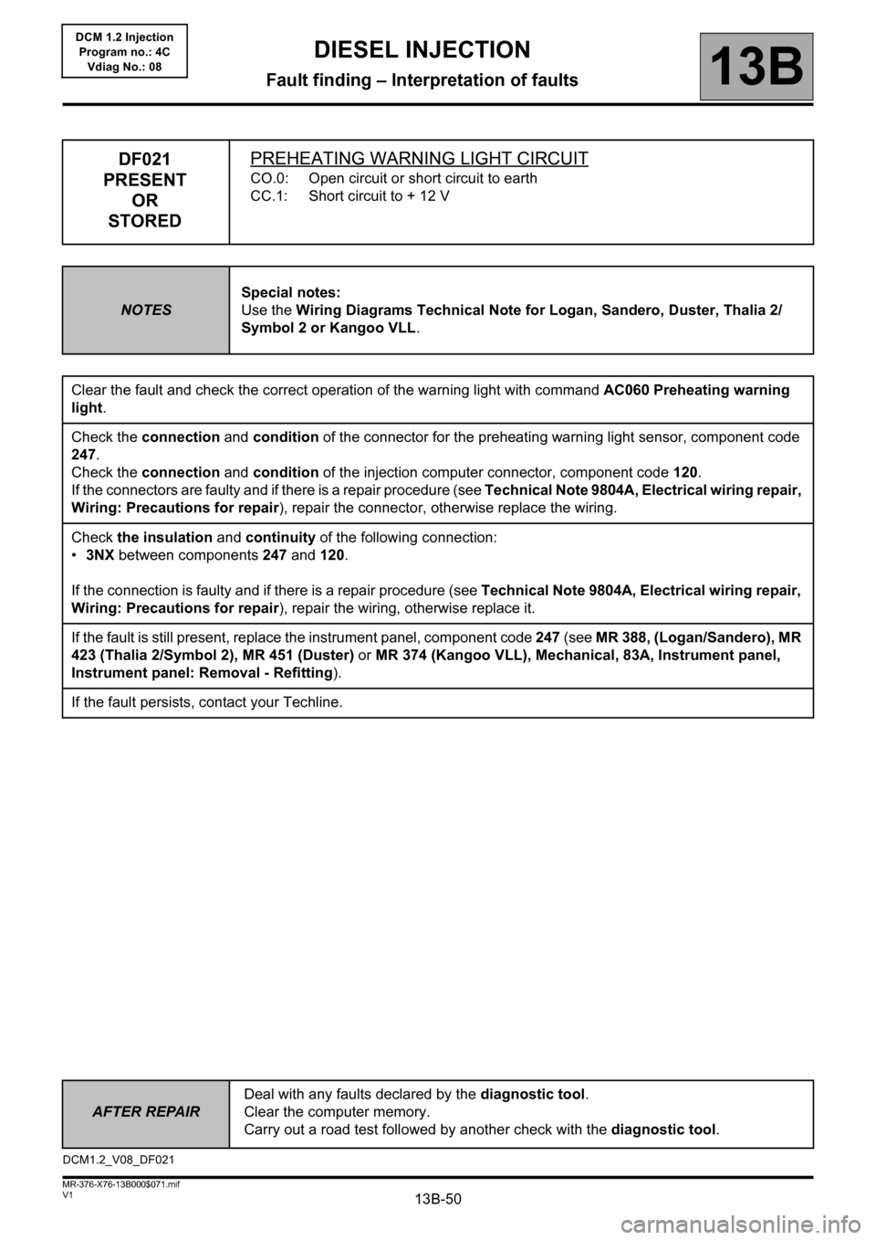
13B-50
AFTER REPAIRDeal with any faults declared by the diagnostic tool.
Clear the computer memory.
Carry out a road test followed by another check with the diagnostic tool.
V1 MR-376-X76-13B000$071.mif
DIESEL INJECTION
Fault finding – Interpretation of faults13B
DCM 1.2 Injection
Program no.: 4C
Vdiag No.: 08
DF021
PRESENT
OR
STOREDPREHEATING WARNING LIGHT CIRCUIT
CO.0: Open circuit or short circuit to earth
CC.1: Short circuit to + 12 V
NOTESSpecial notes:
Use the Wiring Diagrams Technical Note for Logan, Sandero, Duster, Thalia 2/
Symbol 2 or Kangoo VLL.
Clear the fault and check the correct operation of the warning light with command AC060 Preheating warning
light.
Check the connection and condition of the connector for the preheating warning light sensor, component code
247.
Check the connection and condition of the injection computer connector, component code 120.
If the connectors are faulty and if there is a repair procedure (see Technical Note 9804A, Electrical wiring repair,
Wiring: Precautions for repair), repair the connector, otherwise replace the wiring.
Check the insulation and continuity of the following connection:
•3NX between components 247 and 120.
If the connection is faulty and if there is a repair procedure (see Technical Note 9804A, Electrical wiring repair,
Wiring: Precautions for repair), repair the wiring, otherwise replace it.
If the fault is still present, replace the instrument panel, component code 247 (see MR 388, (Logan/Sandero), MR
423 (Thalia 2/Symbol 2), MR 451 (Duster) or MR 374 (Kangoo VLL), Mechanical, 83A, Instrument panel,
Instrument panel: Removal - Refitting).
If the fault persists, contact your Techline.
DCM1.2_V08_DF021