RENAULT SCENIC 2008 J84 / 2.G Multimedia ITS User Guide
Manufacturer: RENAULT, Model Year: 2008, Model line: SCENIC, Model: RENAULT SCENIC 2008 J84 / 2.GPages: 71
Page 11 of 71
MULTIMEDIA
Fault finding - Replacement of components86C
86C-11V5 MR-372-J84-86C050$312.mif
ITS
Program No.: 0020
Vdiag No.: 04MULTIMEDIA
Fault finding - Replacement of components
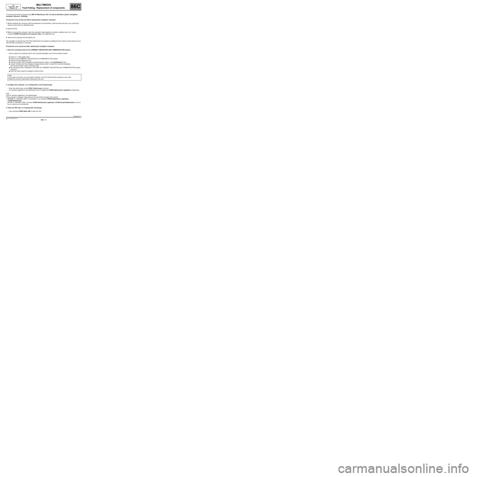
To remove and refit this computer (see MR 370 Mechanical, 83C, On-board telematics system, Navigation
computer: Removal - Refitting).
Procedures to be carried out before replacing the navigation computer:
1. Before replacing the computer (with the agreement of the Techline), read the faults and carry out a conformity
check to ensure that it is definitely faulty.
2. Eject the DVD.
3. Before removing the computer, clear the customer's data (telephone numbers, address book, etc.) using
command RZ003 Parameters and customer data in the diagnostic tool.
4. Remove the computer with the ignition off.
The navigation computers from the Parts Department are supplied unconfigured and in factory mode (receiver set to
162 kHz AM, and beeps for 2 minutes).
Procedures to be carried out after replacing the navigation computer:
1. Enter the unlocking code for the CARMINAT NAVIGATION AND COMMUNICATION system.
–How to obtain the unlocking code for the Carminat Navigation and Communication system
●switch on + after ignition feed,
●switch on the CARMINAT NAVIGATION and COMMUNICATION system,
●connect the Clip diagnostic tool,
●note the number of the navigation programming key written in the Identification menu,
●contact Techline with this navigation programming number to obtain the Carminat Navigation
and Communication system unlocking code,
●the unlocking code is requested 2 mins after the CARMINAT NAVIGATION and COMMUNICATION system
comes on,
●enter this code using the navigation central control.
2. Configure the computer (see Configurations and Programming).
–Enter the vehicle type via the CF001 Vehicle type command.
–For vehicles registered in the Netherlands only, complete the VP004 Netherlands Legislation configuration.
Note:
(only for vehicles registered in the Netherlands)
If the computer is replaced. Depending on the manufacturing date of the vehicle:
–BEFORE 01 JANUARY 2006, it is essential to run command VP004 Netherlands Legislation
(LC002 Netherlands)
–AFTER 01 JANUARY 2006, command VP004 Netherlands Legislation (LC002 Except Netherlands) must not
be run under any circumstances.
3. Enter the VIN code (see Dealing with commands).
–Use command VP002 Write VIN to enter the VIN. Note:
If the code is incorrect, you must wait for between 2 and 32 minutes before entering a new code.
Delete the incorrect code before entering the new one.
ITSJ84ph2V1.0
MR-372-J84-86C050$312.mif
Page 12 of 71
MULTIMEDIA
Fault finding - Configurations and programming86C
86C-12V5 MR-372-J84-86C050$364.mif
ITS
Program No.: 0020
Vdiag No.: 04MULTIMEDIA
Fault finding - Configurations and programming
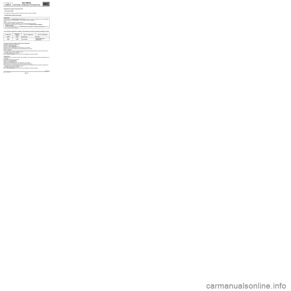
Configurations available and operating mode
–Vehicle type (CF001):
This configuration enables the system to identify the vehicle in which it is installed.
–NETHERLANDS LEGISLATION (VP004):
List of individual configurations available on the diagnostic tool with the associated configuration reading
Procedure to follow to modify the Vehicle Type configuration.
●Establish dialogue with the computer.
●Select the menu repair mode.
●Select the Write configuration menu.
●Select the line corresponding to the configuration to be modified.
●Select the line in the drop-down menu that corresponds to the vehicle.
●Click on Confirm.
●Exit diagnostic mode (ends dialogue with the computer without switching off the tool), switch off the ignition for
5 seconds and then switch the ignition back on.
●Establish dialogue with the computer.
●In the Read configuration menu, check that the configuration has been completed.
Programming
Procedure to follow to modifiy the Country Type configuration (this programming only affects the Netherlands and is
irreversible).
●Establish dialogue with the computer.
●Select the menu repair mode.
●Select the Programming menu.
●Select the line corresponding to the configuration to be modified.
●Select the line in the drop-down menu that corresponds to the country.
●Exit diagnostic mode (ends dialogue with the computer without switching off the tool), switch off the ignition for
5 seconds and then switch the ignition back on.
●Establish dialogue with the computer.
●In the Read configuration menu, check that the configuration has been completed. IMPORTANT
Running command NETHERLANDS LEGISLATION initialises the computer according to this country's legislation.
This configuration is IRREVERSIBLE: it is not possible to clear this selection.
Note:
(only for vehicles registered in the Netherlands)
If the computer is replaced. Depending on the manufacturing date of the vehicle:
–BEFORE 01 JANUARY 2006, it is essential to run command VP004 Netherlands Legislation
(LC002 Netherlands)
–AFTER 01 JANUARY 2006, command VP004 Netherlands Legislation (LC002 Except Netherlands) must not
be run under any circumstances.
ConfigurationConfiguration
readingName of configuration Choice of configuration
CF001 LC001 Vehicle type Scenic II
VP004 LC002 Country typeExcept Netherlands
Netherlands
ITSJ84ph2V1.0
MR-372-J84-86C050$364.mif
Page 13 of 71
MULTIMEDIA
Fault finding - Fault summary table
86C
86C - 13V5 MR-372-J84-86C050$416.mif
ITS
Program no.: 0020
Vdiag No.: 04MULTIMEDIA
Fault finding - Fault summary table
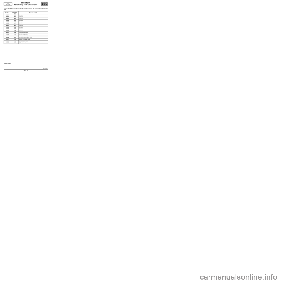
Summary of faults that can be diagnosed by the navigation computer, with corresponding technical center
codes.
Tool faultAssociated
DTCDiagnostic tool title
DF001 D010Computer
DF002 D011Computer
DF003 9A01Computer
DF004 9A02Computer
DF005 9A03Computer
DF006 9A04Computer
DF007 9A07Computer
DF008 9A08Computer
DF009 9A10Computer
DF010 9A0DComputer
DF021 C300Computer configuration
DF022 C186No radio multiplex signal
DF023 9A06No display multiplex signal
DF025 C163No central control multiplex signal
DF027 C189No audio CD changer signals
DF029 9A0CNavigation DVD reader
DF030 9A00GPS aerial circuit*
* Satellite guidance
ITSJ84ph2V1.0
MR-372-J84-86C050$416.mif
Page 14 of 71
MULTIMEDIA
Fault finding - Interpretation of faults
86C
86C - 14V5 MR-372-J84-86C050$468.mif
ITS
Program No.: 0020
Vdiag No.: 04MULTIMEDIA
Fault finding - Interpretation of faults
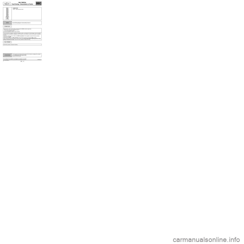
DF001
DF002
DF003
DF004
DF005
DF006
DF007
DF008
DF009
DF010
PRESENT
OR
STOREDCOMPUTER
1.DEF : Internal electronic fault
NOTESUse the Wiring Diagrams Technical Note, Scenic II.
STORED FAULT
Clear the fault, switch off the ignition and disconnect the 20A computer supply fuse.
–Refit the fuse and switch the ignition back on.
–Turn on the navigation system.
If the fault reappears as stored, contact Techline.
If the fault does not reappear: operate the navigation system, including the CD multi-changer, the tuner-amplifier
and the hands-free telephone integrated control (if present on the vehicle) to check that the system is operating
correctly.
Check the conformity of the + 12 V on the BCP3 connection of the navigation computer 40-track connector
(component code 662).
Check that the earth on the MX connection of the 40-track connector of component 662 is perfect.
If any connection is faulty and if there is a repair method (see Technical Note 6015A, Repairing electrical wiring,
Wiring: Precautions for repair), repair the wiring; otherwise, replace the wiring.
FAULT PRESENT
If the fault is present, contact the Techline.
AFTER REPAIRIf the computer was replaced (at the request of the Techline), reconfigure the computer
(see Configurations and programming).
Deal with any other faults.
ITS_V04_DF001 /ITS_V04_DF002/ITS_V04_DF003/ITS_V04_DF004 /ITS_V04_DF005 /
ITS_V04_DF006 /ITS_V04_DF007/ITS_V04_DF008/ITS_V04_DF009 /ITS_V04_DF010 ITSJ84ph2V1.0
MR-372-J84-86C050$468.mif
Page 15 of 71
MULTIMEDIA
Fault finding - Interpretation of faults
86C
86C - 15V5 MR-372-J84-86C050$468.mif
ITS
Program No.: 0020
Vdiag No.: 04
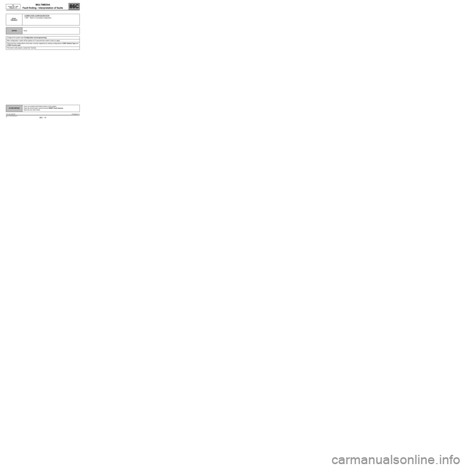
DF021
PRESENT
COMPUTER CONFIGURATION
1.DEF : Blank or incomplete configuration
NOTESNone
Configure the system (see Configuration and programming).
After configuration, switch off the ignition for 5 seconds then switch it back on again.
Check that the configurations have been correctly registered by reading configurations LC001 Vehicle Type and
LC002 Country type.
If the fault is still present, contact the Techline.
AFTER REPAIRCarry out another fault finding check on the system.
Clear the stored faults using command RZ001 Fault memory.
Deal with any other faults.
ITS_V04_DF021PITSJ84ph2V1.0
Page 16 of 71
MULTIMEDIA
Fault finding - Interpretation of faults
86C
86C - 16V5 MR-372-J84-86C050$468.mif
ITS
Program No.: 0020
Vdiag No.: 04
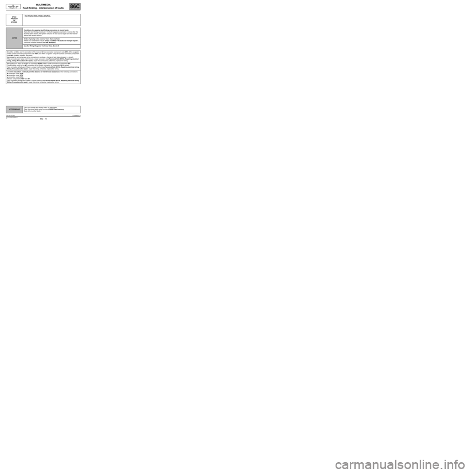
DF022
PRESENT
OR
STOREDNO RADIO MULTIPLEX SIGNAL
NOTESConditions for applying fault finding procedures to stored faults:
Apply this fault finding procedure if the fault reappears as present or stored after the
fault has been cleared, the ignition switched off and back on again and the receiver
started with several actions.
Order of priority in the event of more than one fault:
If there is a combination of faults DF022 and DF027 "No audio CD changer signals",
check the multiplex network (see 88B, Multiplex).
Use the Wiring Diagrams Technical Note, Scenic II.
Check the condition and the connection of the receiver 32-track connector (component code 261), of the navigation
central control connector (component code 1657) and of the navigation computer 32-track connector (component
code 662) (broken, oxidised, bent tabs).
Manipulate the wiring harness at the connectors to produce a change in fault status (present → stored).
If the connectors are faulty and if there is a repair procedure (see Technical Note 6015A, Repairing electrical
wiring, wiring: Precautions for repair), repair the connector(s); otherwise, replace the wiring.
With ignition on, check for + 12 V on connection BCP3 of the 8-track connector on component 261.
Check that the earth on the MT connection of the 8-track connector on component 261 is perfect.
If any connection is faulty and if there is a repair method (see Technical Note 6015A, Repairing electrical wiring,
Wiring: Precautions for repair), repair the wiring; otherwise, replace the wiring.
Check the insulation, continuity and the absence of interference resistance on the following connections:
●connection code 107W,
●connection code 107X,
●connection code 34HU,
between components 1657 and 261.
If any connection is faulty and if there is a repair method (see Technical Note 6015A, Repairing electrical wiring,
Wiring: Precautions for repair), repair the wiring; otherwise, replace the wiring.
AFTER REPAIRCarry out another fault finding check on the system.
Clear the stored faults using command RZ001 Fault memory.
Deal with any other faults.
ITS_V04_DF022ITSJ84ph2V1.0
Page 17 of 71
MULTIMEDIA
Fault finding - Interpretation of faults
86C
86C - 17V5 MR-372-J84-86C050$468.mif
ITS
Program No.: 0020
Vdiag No.: 04
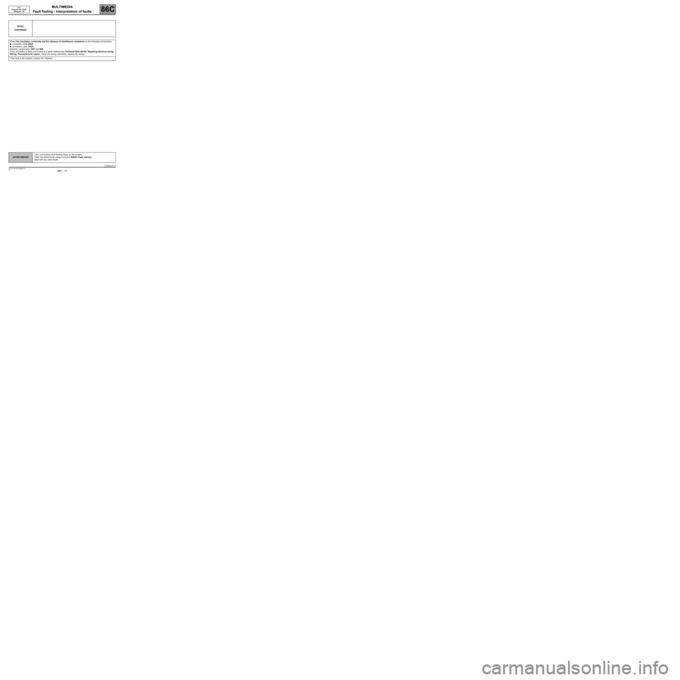
DF022
CONTINUED
Check the insulation, continuity and the absence of interference resistance on the following connections:
●connection code 34DZ,
●connection code 34GA,
between components 1657 and 662.
If any connection is faulty and if there is a repair method (see Technical Note 6015A, Repairing electrical wiring,
Wiring: Precautions for repair), repair the wiring; otherwise, replace the wiring.
If the fault is still present, contact the Techline.
AFTER REPAIRCarry out another fault finding check on the system.
Clear the stored faults using command RZ001 Fault memory.
Deal with any other faults.
ITSJ84ph2V1.0
Page 18 of 71
MULTIMEDIA
Fault finding - Interpretation of faults
86C
86C - 18V5 MR-372-J84-86C050$468.mif
ITS
Program No.: 0020
Vdiag No.: 04
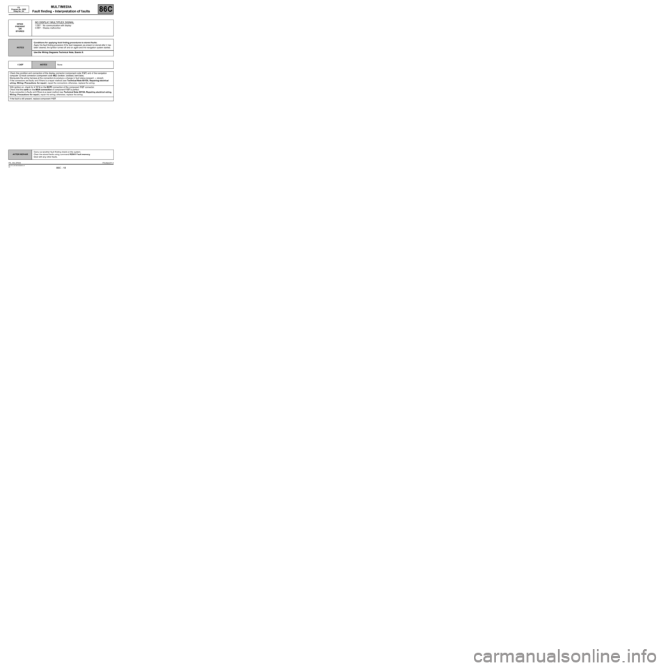
DF023
PRESENT
OR
STOREDNO DISPLAY MULTIPLEX SIGNAL
1.DEF : No communication with display
2.DEF : Display malfunction
NOTESConditions for applying fault finding procedures to stored faults:
Apply this fault finding procedure if the fault reappears as present or stored after it has
been cleared, the ignition turned off and on again and the navigation system started.
Use the Wiring Diagrams Technical Note, Scenic II.
1.DEF
NOTESNone
Check the condition and connection of the display connector (component code 1127) and of the navigation
computer 32-track connector (component code 662) (broken, oxidised, bent tabs).
Manipulate the wiring harness at the connectors to produce a change in fault status (present → stored).
If the connectors are faulty and if there is a repair method (see Technical Note 6015A, Repairing electrical
wiring, Wiring: Precautions for repair), repair the connectors; otherwise, replace the wiring.
With ignition on, check for + 12 V on the BCP3 connection of the component 1127 connector.
Check that the earth on the MAN connection of component 1127 is perfect.
If any connection is faulty and if there is a repair method (see Technical Note 6015A, Repairing electrical wiring,
Wiring: Precautions for repair), repair the wiring; otherwise, replace the wiring.
If the fault is still present, replace component 1127.
AFTER REPAIRCarry out another fault finding check on the system.
Clear the stored faults using command RZ001 Fault memory.
Deal with any other faults.
ITS_V04_DF023ITSJ84ph2V1.0
Page 19 of 71
MULTIMEDIA
Fault finding - Interpretation of faults
86C
86C - 19V5 MR-372-J84-86C050$468.mif
ITS
Program No.: 0020
Vdiag No.: 04
DF023
CONTINUED
2.DEF
NOTESNone
Check the condition and connection of the display connector (component code 1127) and of the navigation
computer 32-track connector (component code 662) (broken, oxidised, bent tabs).
Manipulate the wiring harness at the connectors to produce a change in fault status (present → stored).
If the connectors are faulty and if there is a repair method (see Technical Note 6015A, Repairing electrical
wiring, Wiring: Precautions for repair), repair the connectors; otherwise, replace the wiring.
Check the insulation, continuity and the absence of interference resistance on the following connections:
●connection code TB30,
●connection code TB31,
●connection code 34HA,
●connection code 34GZ,
●connection code 34HU,
between components 662 and 1127.
If any connection is faulty and if there is a repair method (see Technical Note 6015A, Repairing electrical wiring,
Wiring: Precautions for repair), repair the wiring; otherwise, replace the wiring.
If the fault is still present, contact the Techline.
AFTER REPAIRCarry out another fault finding check on the system.
Clear the stored faults using command RZ001 Fault memory.
Deal with any other faults.
ITSJ84ph2V1.0
Page 20 of 71
MULTIMEDIA
Fault finding - Interpretation of faults
86C
86C - 20V5 MR-372-J84-86C050$468.mif
ITS
Program No.: 0020
Vdiag No.: 04
DF025
PRESENT
OR
STOREDNO CENTRAL CONTROL MULTIPLEX SIGNAL
1.DEF : No communication with the central control
NOTESConditions for applying fault finding procedures to stored faults:
Apply this fault finding procedure if the fault reappears as present or stored after the
fault has been cleared, the ignition switched off and back on again and the navigation
system started after using the central control several times.
If faults DF022 No radio multiplex signal, DF025 No central control multiplex
signal and DF027 No audio CD changer signals are present at the same time, check
the multimedia network (see 88B, Multiplexing).
Use the Wiring Diagrams Technical Note, Scenic II.
Check the condition and connection of the navigation central control connector (component code 1657) and of the
navigation computer 32-track connector (component code 662) (broken, oxidised, bent tabs).
Manipulate the wiring harness at the connectors to produce a change in fault status (present → stored).
If the connectors are faulty and if there is a repair method (see Technical Note 6015A, Repairing electrical
wiring, Wiring: Precautions for repair), repair the connectors; otherwise, replace the wiring.
With ignition on, check for + 12 V on the BCP3 connection of component 1657.
Check that the earth on the MX connection on the component 1657 connector is perfect.
If any connection is faulty and if there is a repair method (see Technical Note 6015A, Repairing electrical wiring,
Wiring: Precautions for repair), repair the wiring; otherwise, replace the wiring.
Check the insulation, continuity and the absence of interference resistance on the following connections:
●connection code 34DZ,
●connection code 34GA,
●connection code 34HU,
between components 1657 and 662.
If any connection is faulty and if there is a repair method (see Technical Note 6015A, Repairing electrical wiring,
Wiring: Precautions for repair), repair the wiring; otherwise, replace the wiring.
If the fault is still present, contact the Techline.
AFTER REPAIRCarry out another fault finding check on the system.
Clear the stored faults using command RZ001 Fault memory.
Deal with any other faults.
ITS_V04_DF025ITSJ84ph2V1.0