ignition RENAULT SCENIC 2008 J84 / 2.G Passenger Comparment Connection Unit User Guide
[x] Cancel search | Manufacturer: RENAULT, Model Year: 2008, Model line: SCENIC, Model: RENAULT SCENIC 2008 J84 / 2.GPages: 391
Page 26 of 391
PASSENGER COMPARTMENT CONNECTION UNIT
Fault finding - System operation
87B
87B-26
PASSENGER COMPARTMENT CONNECTION UNIT
Fault finding - System operation
87B
87B-26V9 MR-372-J84-87B000$086.mif
UCH
Vdiag No.: 44, 48,
4C, 4D, 4F, 50
b/ Locking the steering column:
The steering column is locked with the engine off, after the Renault card is removed from the card reader. This
locking operation requires:
–a valid 0 mph (0 km/h) speed signal,
–a correctly functioning airbag and no impact detected,
–a deactivated + after ignition connection.
When the engine has not been started but the after ignition feed is active (e.g. forced after ignition feed), certain
conditions in which there is a drop in the after ignition feed do not cause the steering column to lock ("steering
column not locked" message).
Steering column lock fails if:
1/ Normal non-locking scenarios:
–the card is present in the card reader,
–more than 20 minutes has elapsed with the card in the reader and the engine off,
–the vehicle speed is not zero,
–power is demanded by the steering column lock too frequently.
With regard to vehicles fitted with UCH computer Vdiag 4F or above:
–the Renault card is removed from the card reader when the vehicle is in forced + after ignition feed,
–3 minutes have elapsed following a starting failure due to an engaged gear,
–the Renault card is removed from the card reader following a starting failure due to an engaged gear,
–a front door is open following a starting failure due to an engaged gear and the card is not in the reader.
To lock the steering column, start and stop the engine again.
2/ Abnormal non-locking scenarios:
–the airbag unit is faulty or locked,
–the airbag unit is disconnected,
–the airbag has been triggered,
–the speed signal is not available.
In the event that a steering column does not lock, the driver is informed via the message Steering column not locked.
1.2.3 Locking the injection computer:
When the + after ignition feed has been established, the UCH and the injection computer compare their codes via
the multiplex network. If the codes are identical, the vehicle immobiliser is deactivated (ET046 Immobiliser).
If there is a failure, the immobiliser remains active.
Reactivating protection: the immobiliser is reactivated when the engine stops.
Page 27 of 391
PASSENGER COMPARTMENT CONNECTION UNIT
Fault finding - System operation
87B
87B-27
PASSENGER COMPARTMENT CONNECTION UNIT
Fault finding - System operation
87B
87B-27V9 MR-372-J84-87B000$086.mif
UCH
Vdiag No.: 44, 48,
4C, 4D, 4F, 50
1.2.4 Renault card check by the UCH:
a/ Card check:
When the engine is running, the UCH checks for the presence of the Renault card in the passenger compartment (if
vehicle is hands-free) or in the card-reader when a door is opened then closed. If the Renault card is not detected, a
message on the instrument panel and a buzzer warn the driver.
Command AC036 Internal aerial test is used to check the area covered by the starting aerials inside the passenger
compartment (hands-free vehicles). The card reader flashes when the card is detected.
This command allows a hands-free card to be recognised even if it does not belong to the vehicle.
b/ Low battery warning:
If the Renault card battery is faulty or flat, the change card battery message is displayed on the instrument panel
when the vehicle is started, if there have been 5 attempts to authenticate the Renault card since the battery fault.
c/ Storing information on the card:
A device allowing information relating to the vehicle to be read from the card is available.
Information available: – VIN (Vehicle Identification Number).
–Mileage.
–Fuel level.
–Mileage before oil change.
–Tyre pressure (if vehicle fitted with SSPP).
–Status of OBD warning light.
–Oil level.
2.5 Immobiliser warning light programs
Immobiliser warning light Vehicle protection status
Ignition
offWarning light flashes slowlyVehicle protected (immobiliser active or fault with
steering lock)
Warning light not lit New vehicle or blank UCH storage mode
Ignition
onWarning light flashes slowly Renault card not recognised
Warning light continuously lit Injection authentication fault
Warning light not lit Vehicle unprotected (immobiliser inactive)
Page 33 of 391
PASSENGER COMPARTMENT CONNECTION UNIT
Fault finding - System operation
87B
87B-33
PASSENGER COMPARTMENT CONNECTION UNIT
Fault finding - System operation
87B
87B-33V9 MR-372-J84-87B000$086.mif
UCH
Vdiag No.: 44, 48,
4C, 4D, 4F, 50
1.4.1.6 The door locking motors:
These are direct current motors (12 V supply). The door locking motors are controlled by the UCH.
The deadlocking function requires a second motor per door.
1.4.2 Main components of the PROTECTION sub-function:
The protection sub-function is based on 4 main coded components:
–The Renault cards.
–The UCH.
–The electric steering column lock.
–The injection computer.
These parts are coded definitively: a part coded for one vehicle may not be used on another vehicle.
It is possible to replace a coded part with an uncoded part using special procedures in the CLIP tool and the vehicle
repair code (See Configuration and programming).
1.4.2.1 The Renault card:
The Renault card enables the vehicle to be started in two modes:
–starting by inserting the card into the reader:
–hands-free starting without insertion of the card into the card reader (hands-free vehicles).
The Renault card is powered by a 3 V battery. This battery is necessary to operate in standard and hands-free mode.
If the battery is too old, or if the vehicle is in an area of frequency interference, hands-free starting is not possible, but
always possible by inserting the Renault card into the reader.
1.4.2.2 The UCH:
a) The UCH detects the starting request (Start button pressed under starting conditions).
b) The UCH authenticates the Renault card via the starting aerials for hands-free mode, or via the card reader for
transponder mode.
c) The UCH manages the exchange with the steering column lock:
The UCH sends an unlocking request to the steering column via the vehicle's multiplex network, and the steering
column responds with the status of the lock bolt.
d) The UCH requests activation of the + after ignition feed from the Protection and Switching Unit.
e) The UCH manages the exchange with the injection computer:
The UCH and the injection computer exchange their codes via the vehicle's multiplex network to deactivate protection
and unlock the immobiliser.
f) The UCH requests the Protection and Switching Unit to supply the starter motor.
Page 34 of 391
PASSENGER COMPARTMENT CONNECTION UNIT
Fault finding - System operation
87B
87B-34
PASSENGER COMPARTMENT CONNECTION UNIT
Fault finding - System operation
87B
87B-34V9 MR-372-J84-87B000$086.mif
UCH
Vdiag No.: 44, 48,
4C, 4D, 4F, 50
1.4.2.3 The electric steering column lock:
The electric steering column lock is controlled by the UCH. The steering column lock works by inserting and
removing a lock bolt. It replaces the Neimann type lock.
The steering column lock is powered outside + after ignition feed. The steering column lock supply is via the after
ignition relay (located in the Protection and Switching Unit) in its rest position, from where it is distributed to the
column lock by the UCH.
The UCH sends an unlocking request and a code to the steering column lock, via the vehicle's multiplex network.
The multiplex network unlocks the steering column lock if the code is recognised.
A sensor located on the column lock bolt informs the UCH, via the multiplex network and by wire connection, that it
is unlocked.
When unlocking is confirmed, the UCH activates the + after ignition feed via the Protection and Switching Unit. The
column lock is no longer supplied.
The column lock has a "+ after ignition feed present on vehicle" wire signal which inhibits locking while the feed is
active.
1.4.2.4 The injection computer:
The injection computer is coded and unlocks following the encrypted challenge exchange with the UCH.
1.4.2.5 The starting aerials (hands-free vehicles):
There are 3 transmitter aerials located in the passenger compartment. They are controlled by the UCH to interrogate
the card during a starting request or in confirming the presence of the card in the vehicle (e.g. after a door is
opened).
The power used allows the whole passenger compartment to be covered, including the boot. Overspill outside the
passenger compartment is minimal.
1.4.2.6 The card reader:
The card reader is connected to the UCH by a wire connection. It provides the transponder function (like a key
recognition ring). It therefore allows authentication of a Renault card without a battery.
If the card is not detected or recognised during hands-free starting, the card reader flashes to tell the customer to
insert the Renault card.IMPORTANT IMPORTANT
The steering column lock is:
–not removable when the bolt is disengaged,
–fitted with a left-hand thread self-shearing mounting bolt.
Page 40 of 391
PASSENGER COMPARTMENT CONNECTION UNIT
Fault finding - System operation
87B
87B-40
PASSENGER COMPARTMENT CONNECTION UNIT
Fault finding - System operation
87B
87B-40V9 MR-372-J84-87B000$129.mif
UCH
Vdiag No.: 44, 48,
4C, 4D, 4F, 50
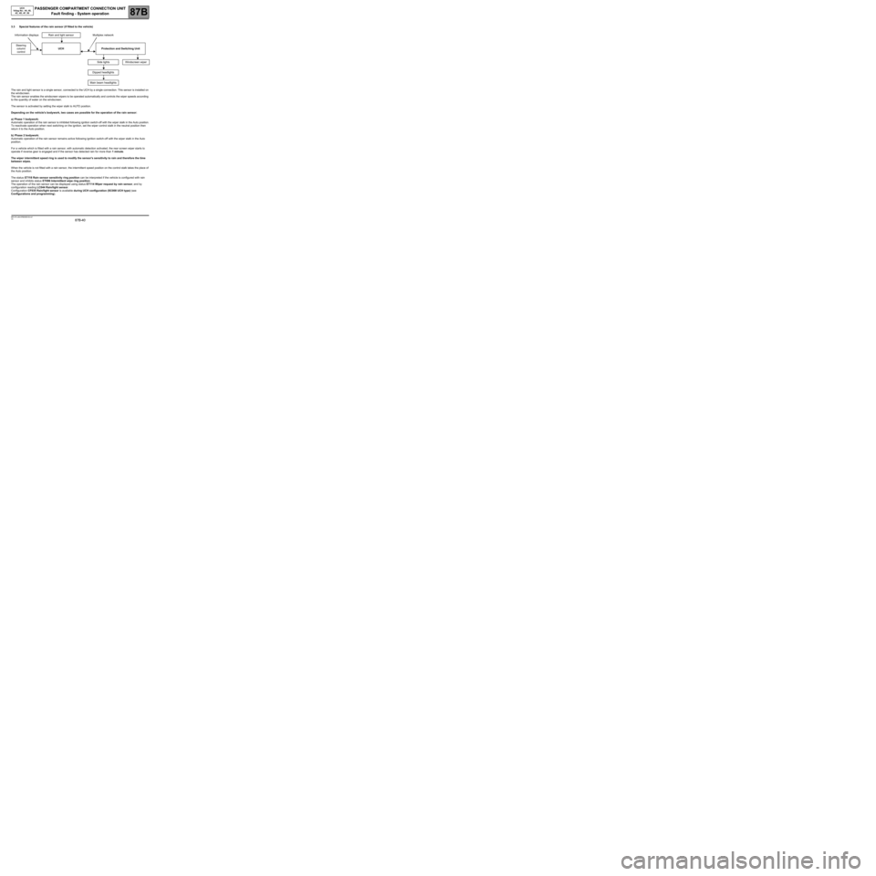
3.3 Special features of the rain sensor (if fitted to the vehicle)
The rain and light sensor is a single sensor, connected to the UCH by a single connection. This sensor is installed on
the windscreen.
The rain sensor enables the windscreen wipers to be operated automatically and controls the wiper speeds according
to the quantity of water on the windscreen.
The sensor is activated by setting the wiper stalk to AUTO position.
Depending on the vehicle's bodywork, two cases are possible for the operation of the rain sensor:
a) Phase 1 bodywork:
Automatic operation of the rain sensor is inhibited following ignition switch-off with the wiper stalk in the Auto position.
To reactivate operation when next switching on the ignition, set the wiper control stalk in the neutral position then
return it to the Auto position.
b) Phase 2 bodywork:
Automatic operation of the rain sensor remains active following ignition switch-off with the wiper stalk in the Auto
position.
For a vehicle which is fitted with a rain sensor, with automatic detection activated, the rear screen wiper starts to
operate if reverse gear is engaged and if the sensor has detected rain for more than 1 minute.
The wiper intermittent speed ring is used to modify the sensor's sensitivity to rain and therefore the time
between wipes.
When the vehicle is not fitted with a rain sensor, the intermittent speed position on the control stalk takes the place of
the Auto position.
The status ET118 Rain sensor sensitivity ring position can be interpreted if the vehicle is configured with rain
sensor and inhibits status ET096 Intermittent wipe ring position.
The operation of the rain sensor can be displayed using status ET114 Wiper request by rain sensor, and by
configuration reading LC044 Rain/light sensor.
Configuration CF035 Rain/light sensor is available during UCH configuration (SC008 UCH type) (see
Configurations and programming). Information displays Rain and light sensor Multiplex network
Steering
column
control UCH Protection and Switching Unit
Side lights Windscreen wiper
Dipped headlights
Main beam headlights
Page 48 of 391
PASSENGER COMPARTMENT CONNECTION UNIT
Fault finding - System operation
87B
87B-48
PASSENGER COMPARTMENT CONNECTION UNIT
Fault finding - System operation
87B
87B-48V9 MR-372-J84-87B000$129.mif
UCH
Vdiag No.: 44, 48,
4C, 4D, 4F, 50
MATCHING THE VALVE TO THE TYRE
Whenever wheels are swapped over, reprogram the new valve positions in the UCH using the diagnostic tool.
The coloured rings will then have to be placed back in the location marked on the label on the driver's door.
Ring colours:
–Front left-hand: green.
–Front right-hand: yellow.
–Rear left-hand: red.
–Rear right-hand: black.
WINTER AND SUMMER TYRES
On leaving the factory, it is the summer wheel set that is configured in the UCH, but customers can fit their vehicle
with a winter set (winter wheels = wheel rims + sensors + special tyres).
The first time a set of winter wheels is fitted, program the codes of the four valves. Thereafter, whenever the set of
tyres is changed, recognition is automatic without having to touch the UCH.
Establishing communication between the UCH and the CLIP diagnostic tool:
–Connect the wire to the diagnostic socket and switch on the ignition.
–Switch on the diagnostic tool.
–Select the vehicle type and carry out the multiplex network test.
–Select the Tyre function.
–Follow the fault finding procedure described previously.
Page 49 of 391
PASSENGER COMPARTMENT CONNECTION UNIT
Fault finding - Replacement of components PASSENGER COMPARTMENT CONNECTION UNIT
Fault finding - Replacement of components
87B
87B-49
87B
87B-49V9 MR-372-J84-87B000$172.mif
UCH
Vdiag No.: 44, 48,
4C, 4D, 4F, 50PASSENGER COMPARTMENT CONNECTION UNIT
Fault finding - Replacement of components
REPLACING THE UCH COMPUTER
Switch off the ignition before replacing the UCH.
After replacing the UCH, configure the new computer for the equipment present on the vehicle.
●Configure the UCH: WITH or WITHOUT Tyre pressure monitor function using command CF023 Tyre pressure
monitor function in scenario SC008 UCH type.
●Enter the recommended pressures with command VP005 Enter recommended pressures.
●Program the four valve codes using command SC002 Program the four valve codes.
The configurations are described under the Configuration and programming section.
REPLACING ONE OR MORE VALVES
Program the UCH with the new valve code by running command SC002 described in the Configuration and
programming section.
Note: Program all four valve codes even if only one valve has been replaced.
REPLACING THE INSTRUMENT PANEL
After replacing the instrument panel, configure it for the equipment installed in the vehicle.
Configure the tyre pressure monitor function WITH or WITHOUT in the instrument panel using command CF145
Tyre pressure monitor (see 83A, Instrument panel).
MR-372-J84-87B000$172.mif
Page 56 of 391
PASSENGER COMPARTMENT CONNECTION UNIT
Fault finding - Configurations and programming
87B
87B-56
PASSENGER COMPARTMENT CONNECTION UNIT
Fault finding - Configurations and programming
87B
87B-56V9 MR-372-J84-87B000$215.mif
UCH
Vdiag No.: 44, 48,
4C, 4D, 4F, 50
4/ INJECTION COMPUTER PROGRAMMING:
A blank injection computer is automatically programmed when + after ignition feed is first activated on the vehicle.
After this, the injection computer has been programmed definitively. The injection computer can no longer be used
on another vehicle.
Programming will operate correctly if:
–the cards and UCH are programmed,
–the steering column lock is programmed (to activate + after ignition feed),
–the injection computer is blank.
Page 72 of 391
PASSENGER COMPARTMENT CONNECTION UNIT
Fault finding - Interpretation of faults
87B
87B-72
PASSENGER COMPARTMENT CONNECTION UNIT
Fault finding - Interpretation of faults
87B
87B-72V9 MR-372-J84-87B000$301.mif
UCH
Vdiag No.: 44, 48,
4C, 4D, 4F, 50
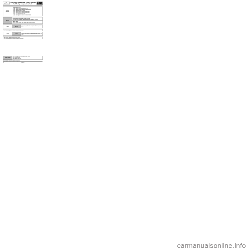
DF002
PRESENT
STEERING LOCK
1.DEF: Steering lock internal electronic fault
2.DEF: Steering column lock internal electronic fault
3.DEF: Mechanical fault on column
4.DEF: Steering column lock authentication fault
5.DEF: Steering column lock authentication fault
6.DEF: UCH internal electronic fault
7.DEF: Steering column lock internal electronic fault
8.DEF: Steering column lock internal electronic fault
NOTESPriorities when dealing with a number of faults:
Firstly, deal with fault DF029 Steering column lock circuit, if it is present.
Special notes:
Attempt to apply forced + after ignition feed to update the faults.
1.DEF
NOTESAttempt to apply forced + after ignition feed to update the
faults.
If the fault is still present, replace the steering column lock.
2.DEF
NOTESAttempt to apply forced + after ignition feed to update the
faults.
Make another attempt to lock/unlock the column.
If the fault is still present, replace the steering column lock.
AFTER REPAIRCarry out another fault finding check on the system.
Clear the stored faults.
Deal with any other faults.
UCH_V44_DF002P/UCH_V48_DF002P/UCH_V4C_DF002P/
UCH_V4D_DF002P/UCH_V4F_DF002P /UCH_V50_DF002P
Page 73 of 391
PASSENGER COMPARTMENT CONNECTION UNIT
Fault finding - Interpretation of faults
87B
87B-73
PASSENGER COMPARTMENT CONNECTION UNIT
Fault finding - Interpretation of faults
87B
87B-73V9 MR-372-J84-87B000$301.mif
UCH
Vdiag No.: 44, 48,
4C, 4D, 4F, 50
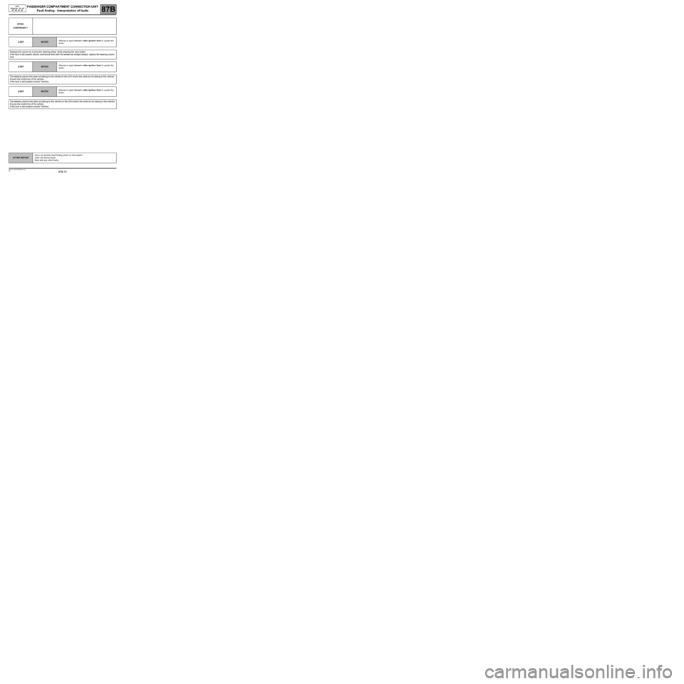
DF002
CONTINUED 1
3.DEF
NOTESAttempt to apply forced + after ignition feed to update the
faults.
Release the column by turning the steering wheel, while pressing the start button.
If the fault is still present without mechanical fault (with the wheels set straight ahead), replace the steering column
lock.
4.DEF
NOTESAttempt to apply forced + after ignition feed to update the
faults.
The steering column lock does not belong to this vehicle (or the UCH and/or the cards do not belong to this vehicle).
Ensure the conformity of the vehicle.
If the fault is still present contact Techline.
5.DEF
NOTESAttempt to apply forced + after ignition feed to update the
faults.
The steering column lock does not belong to this vehicle (or the UCH and/or the cards do not belong to this vehicle).
Ensure the conformity of the vehicle.
If the fault is still present contact Techline.
AFTER REPAIRCarry out another fault finding check on the system.
Clear the stored faults.
Deal with any other faults.