RENAULT SCENIC 2011 J95 / 3.G Engine And Peripherals EDC16 Injection Workshop Manual
Manufacturer: RENAULT, Model Year: 2011, Model line: SCENIC, Model: RENAULT SCENIC 2011 J95 / 3.GPages: 236, PDF Size: 1.32 MB
Page 221 of 236
13B-221
MR-372-J84-13B150$893.mif
V10
DIESEL INJECTION
Fault finding - Tests
EDC16 INJECTION
Program No.: C1
Vdiag No.: 44, 48 and 4C
13B
TEST 1
CONTINUED 3
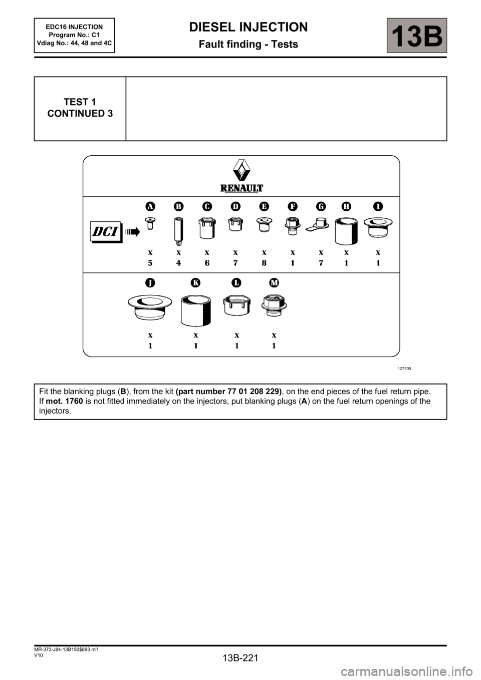
Fit the blanking plugs (B), from the kit (part number 77 01 208 229), on the end pieces of the fuel return pipe.
If mot. 1760 is not fitted immediately on the injectors, put blanking plugs (A) on the fuel return openings of the
injectors.
Page 222 of 236
13B-222
MR-372-J84-13B150$893.mif
V10
DIESEL INJECTION
Fault finding - Tests
EDC16 INJECTION
Program No.: C1
Vdiag No.: 44, 48 and 4C
13B
TEST 1
CONTINUED 4
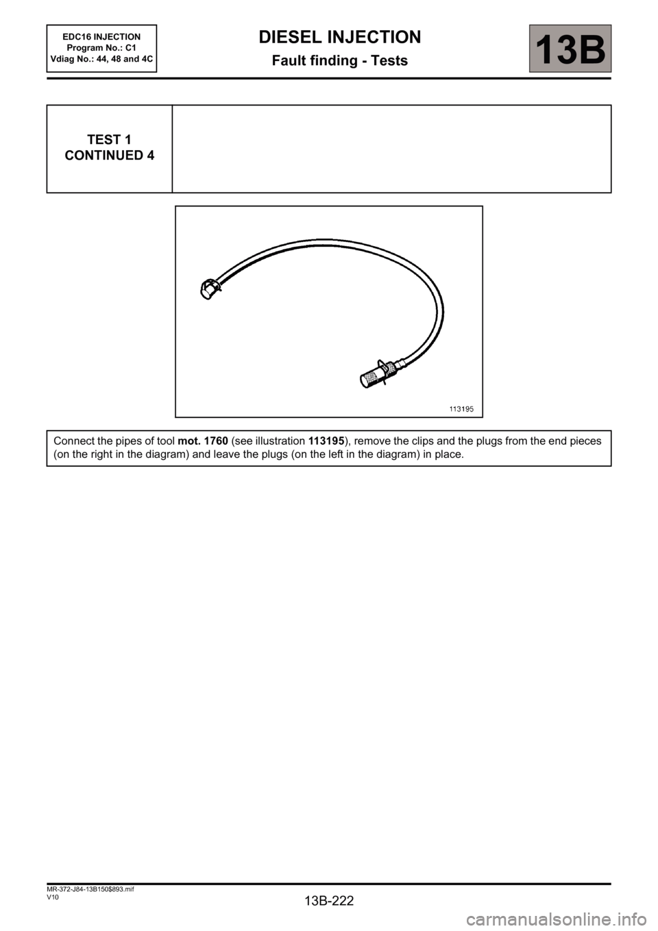
Connect the pipes of tool mot. 1760 (see illustration 113195), remove the clips and the plugs from the end pieces
(on the right in the diagram) and leave the plugs (on the left in the diagram) in place.
Page 223 of 236
13B-223
MR-372-J84-13B150$893.mif
V10
DIESEL INJECTION
Fault finding - Tests
EDC16 INJECTION
Program No.: C1
Vdiag No.: 44, 48 and 4C
13B
TEST 1
CONTINUED 5
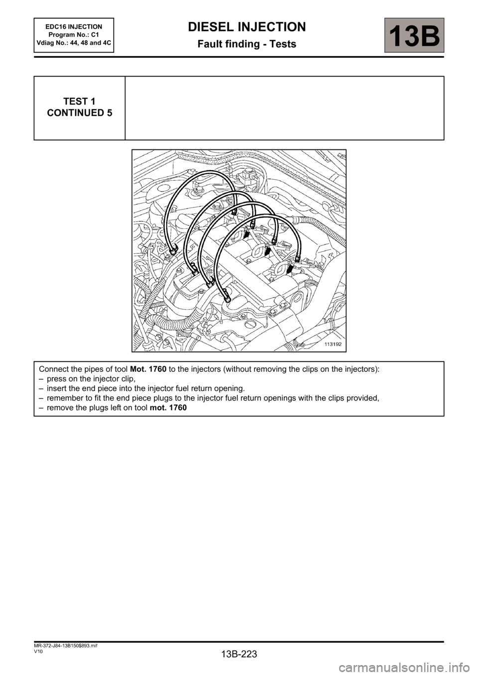
Connect the pipes of tool Mot. 1760 to the injectors (without removing the clips on the injectors):
– press on the injector clip,
– insert the end piece into the injector fuel return opening.
– remember to fit the end piece plugs to the injector fuel return openings with the clips provided,
– remove the plugs left on tool mot. 1760
Page 224 of 236
13B-224
MR-372-J84-13B150$893.mif
V10
DIESEL INJECTION
Fault finding - Tests
EDC16 INJECTION
Program No.: C1
Vdiag No.: 44, 48 and 4C
13B
TEST 1
CONTINUED 6
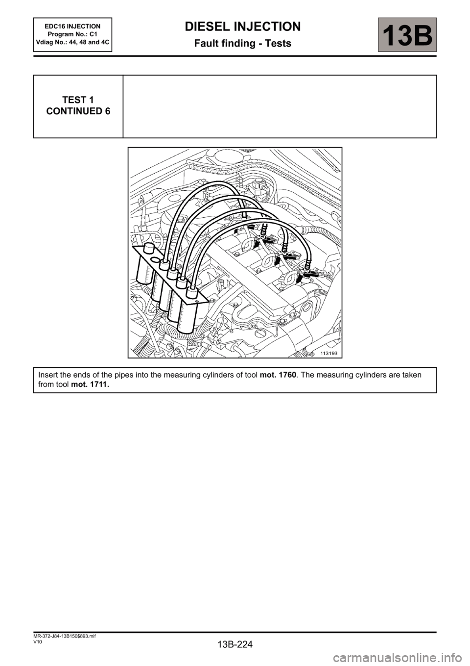
Insert the ends of the pipes into the measuring cylinders of tool mot. 1760. The measuring cylinders are taken
from tool mot. 1711.
Page 225 of 236
13B-225
MR-372-J84-13B150$893.mif
V10
EDC16 INJECTION
Program No.: C1
Vdiag No.: 44, 48 and 4CDIESEL INJECTION
Fault finding - Tests13B
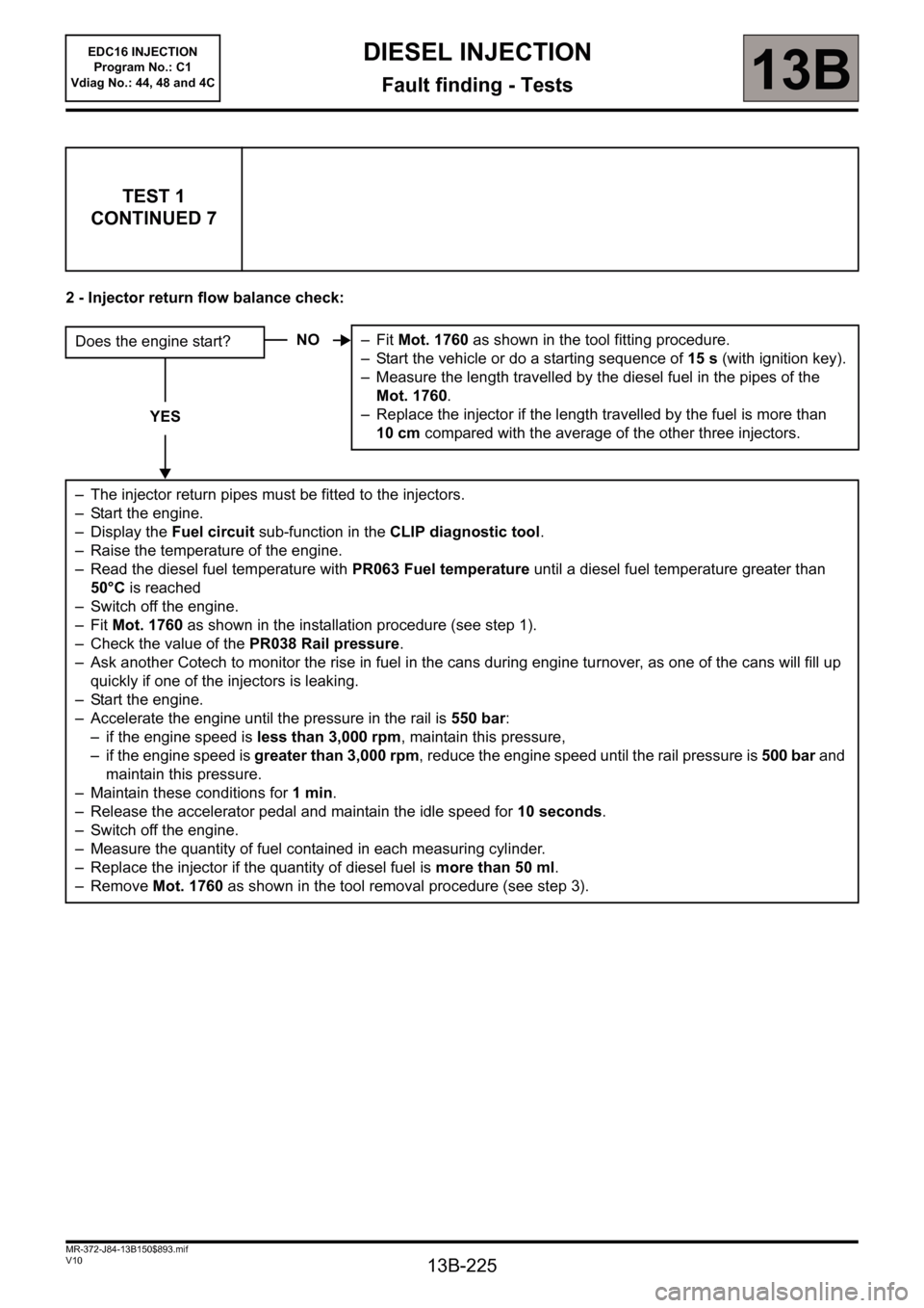
2 - Injector return flow balance check:
TEST 1
CONTINUED 7
Does the engine start?
YES
– The injector return pipes must be fitted to the injectors.
– Start the engine.
– Display the Fuel circuit sub-function in the CLIP diagnostic tool.
– Raise the temperature of the engine.
– Read the diesel fuel temperature with PR063 Fuel temperature until a diesel fuel temperature greater than
50°C is reached
– Switch off the engine.
–Fit Mot. 1760 as shown in the installation procedure (see step 1).
– Check the value of the PR038 Rail pressure.
– Ask another Cotech to monitor the rise in fuel in the cans during engine turnover, as one of the cans will fill up
quickly if one of the injectors is leaking.
– Start the engine.
– Accelerate the engine until the pressure in the rail is 550 bar:
– if the engine speed is less than 3,000 rpm, maintain this pressure,
– if the engine speed is greater than 3,000 rpm, reduce the engine speed until the rail pressure is 500 bar and
maintain this pressure.
– Maintain these conditions for 1min.
– Release the accelerator pedal and maintain the idle speed for 10 seconds.
– Switch off the engine.
– Measure the quantity of fuel contained in each measuring cylinder.
– Replace the injector if the quantity of diesel fuel is more than 50 ml.
– Remove Mot. 1760 as shown in the tool removal procedure (see step 3).NO–Fit Mot. 1760 as shown in the tool fitting procedure.
– Start the vehicle or do a starting sequence of 15 s (with ignition key).
– Measure the length travelled by the diesel fuel in the pipes of the
Mot. 1760.
– Replace the injector if the length travelled by the fuel is more than
10 cm compared with the average of the other three injectors.
Page 226 of 236
13B-226
MR-372-J84-13B150$893.mif
V10
DIESEL INJECTION
Fault finding - Tests
EDC16 INJECTION
Program No.: C1
Vdiag No.: 44, 48 and 4C
13B
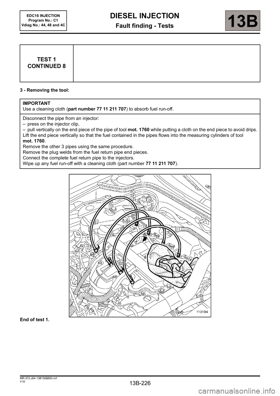
3 - Removing the tool:
End of test 1.
TEST 1
CONTINUED 8
IMPORTANT
Use a cleaning cloth (part number 77 11 211 707) to absorb fuel run-off.
Disconnect the pipe from an injector:
– press on the injector clip,
– pull vertically on the end piece of the pipe of tool mot. 1760 while putting a cloth on the end piece to avoid drips.
Lift the end piece vertically so that the fuel contained in the pipes flows into the measuring cylinders of tool
mot. 1760.
Remove the other 3 pipes using the same procedure.
Remove the plug welds from the fuel return pipe end pieces.
Connect the complete fuel return pipe to the injectors.
Wipe up any fuel run-off with a cleaning cloth (part number 77 11 211 707).
Page 227 of 236
13B-227
MR-372-J84-13B150$893.mif
V10
EDC16 INJECTION
Program No.: C1
Vdiag No.: 44, 48 and 4CDIESEL INJECTION
Fault finding - Tests13B
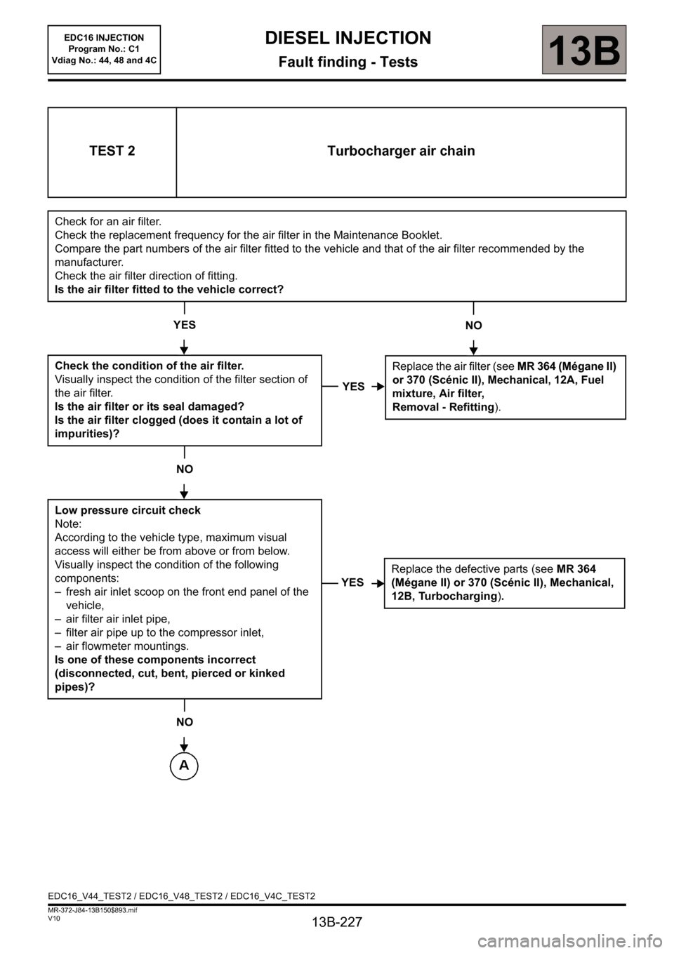
TEST 2 Turbocharger air chain
Check for an air filter.
Check the replacement frequency for the air filter in the Maintenance Booklet.
Compare the part numbers of the air filter fitted to the vehicle and that of the air filter recommended by the
manufacturer.
Check the air filter direction of fitting.
Is the air filter fitted to the vehicle correct?
YES
Check the condition of the air filter.
Visually inspect the condition of the filter section of
the air filter.
Is the air filter or its seal damaged?
Is the air filter clogged (does it contain a lot of
impurities)?
NO
Low pressure circuit check
Note:
According to the vehicle type, maximum visual
access will either be from above or from below.
Visually inspect the condition of the following
components:
– fresh air inlet scoop on the front end panel of the
vehicle,
– air filter air inlet pipe,
– filter air pipe up to the compressor inlet,
– air flowmeter mountings.
Is one of these components incorrect
(disconnected, cut, bent, pierced or kinked
pipes)?
NO
NO
YES
Replace the air filter (see MR 364 (Mégane II)
or 370 (Scénic II), Mechanical, 12A, Fuel
mixture,
Air filter,
Removal - Refitting
).
YESReplace the defective parts (see MR 364
(Mégane II) or 370 (Scénic II), Mechanical,
12B, Turbocharging).
EDC16_V44_TEST2 / EDC16_V48_TEST2 / EDC16_V4C_TEST2
Page 228 of 236
13B-228
MR-372-J84-13B150$893.mif
V10
EDC16 INJECTION
Program No.: C1
Vdiag No.: 44, 48 and 4CDIESEL INJECTION
Fault finding - Tests13B
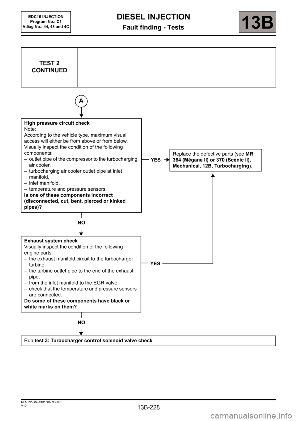
TEST 2
CONTINUED
High pressure circuit check
Note:
According to the vehicle type, maximum visual
access will either be from above or from below.
Visually inspect the condition of the following
components:
– outlet pipe of the compressor to the turbocharging
air cooler,
– turbocharging air cooler outlet pipe at inlet
manifold,
– inlet manifold,
– temperature and pressure sensors.
Is one of these components incorrect
(disconnected, cut, bent, pierced or kinked
pipes)?
NO
Exhaust system check
Visually inspect the condition of the following
engine parts:
– the exhaust manifold circuit to the turbocharger
turbine,
– the turbine outlet pipe to the end of the exhaust
pipe,
– from the inlet manifold to the EGR valve,
– check that the temperature and pressure sensors
are connected.
Do some of these components have black or
white marks on them?
NO
Run test 3: Turbocharger control solenoid valve check.
YESReplace the defective parts (see MR
364 (Mégane II) or 370 (Scénic II),
Mechanical, 12B, Turbocharging).
YES
Page 229 of 236
13B-229
MR-372-J84-13B150$893.mif
V10
13B
EDC16 INJECTION
Program No.: C1
Vdiag No.: 44, 48 and 4CDIESEL INJECTION
Fault finding - Tests
1
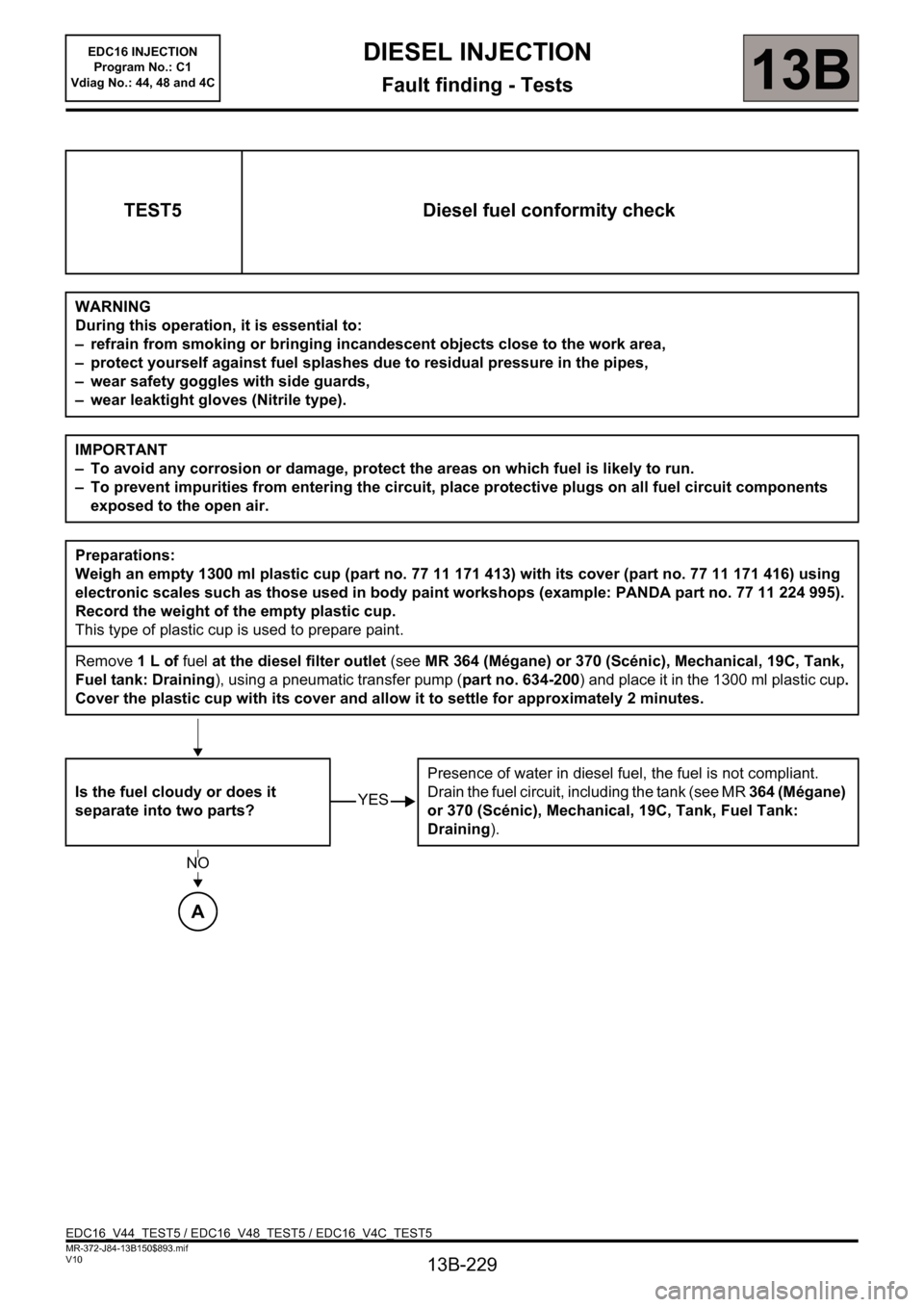
TEST5 Diesel fuel conformity check
WARNING
During this operation, it is essential to:
– refrain from smoking or bringing incandescent objects close to the work area,
– protect yourself against fuel splashes due to residual pressure in the pipes,
– wear safety goggles with side guards,
– wear leaktight gloves (Nitrile type).
IMPORTANT
– To avoid any corrosion or damage, protect the areas on which fuel is likely to run.
– To prevent impurities from entering the circuit, place protective plugs on all fuel circuit components
exposed to the open air.
Preparations:
Weigh an empty 1300 ml plastic cup (part no. 77 11 171 413) with its cover (part no. 77 11 171 416) using
electronic scales such as those used in body paint workshops (example: PANDA part no. 77 11 224 995).
Record the weight of the empty plastic cup.
This type of plastic cup is used to prepare paint.
Remove 1 L of fuel at the diesel filter outlet (see MR 364 (Mégane) or 370 (Scénic), Mechanical, 19C, Tank,
Fuel tank: Draining), using a pneumatic transfer pump (part no. 634-200) and place it in the 1300 ml plastic cup.
Cover the plastic cup with its cover and allow it to settle for approximately 2 minutes.
Is the fuel cloudy or does it
separate into two parts?Presence of water in diesel fuel, the fuel is not compliant.
Drain the fuel circuit, including the tank (see MR 364 (Mégane)
or 370 (Scénic), Mechanical, 19C, Tank, Fuel Tank:
Draining).
YES
NO
A
EDC16_V44_TEST5 / EDC16_V48_TEST5 / EDC16_V4C_TEST5
Page 230 of 236
13B-230
MR-372-J84-13B150$893.mif
V10
13B
EDC16 INJECTION
Program No.: C1
Vdiag No.: 44, 48 and 4CDIESEL INJECTION
Fault finding - Tests
TEST5
CONTINUED
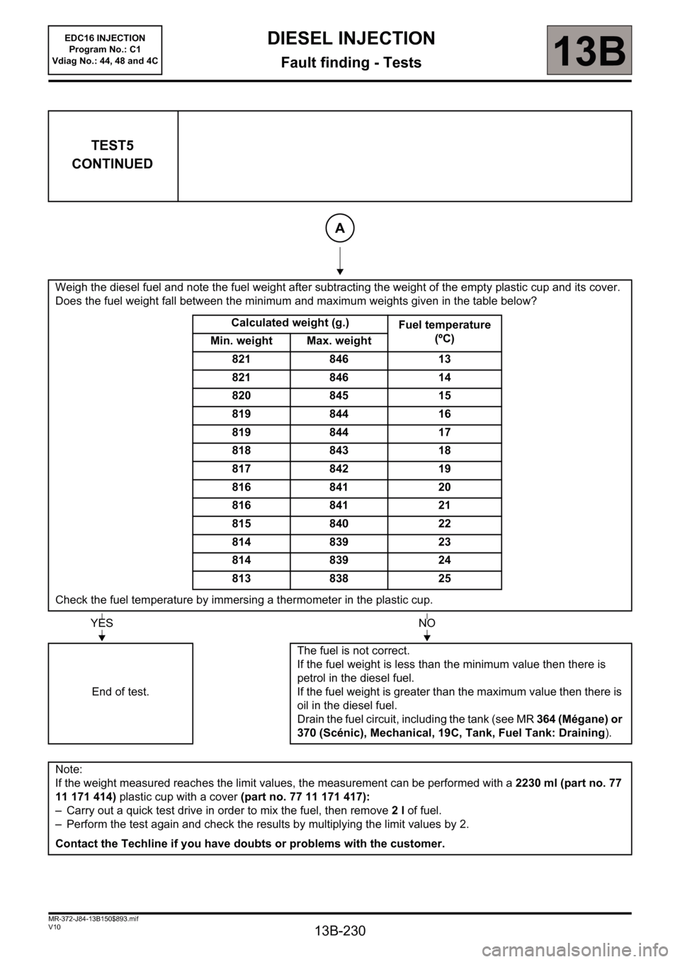
Weigh the diesel fuel and note the fuel weight after subtracting the weight of the empty plastic cup and its cover.
Does the fuel weight fall between the minimum and maximum weights given in the table below?
Calculated weight (g.)
Fuel temperature
(ºC)
Min. weight Max. weight
821 846 13
821 846 14
820 845 15
819 844 16
819 844 17
818 843 18
817 842 19
816 841 20
816 841 21
815 840 22
814 839 23
814 839 24
813 838 25
Check the fuel temperature by immersing a thermometer in the plastic cup.
End of test.The fuel is not correct.
If the fuel weight is less than the minimum value then there is
petrol in the diesel fuel.
If the fuel weight is greater than the maximum value then there is
oil in the diesel fuel.
Drain the fuel circuit, including the tank (see MR 364 (Mégane) or
370 (Scénic), Mechanical, 19C, Tank, Fuel Tank: Draining).
Note:
If the weight measured reaches the limit values, the measurement can be performed with a 2230 ml (part no. 77
11 171 414) plastic cup with a cover (part no. 77 11 171 417):
– Carry out a quick test drive in order to mix the fuel, then remove 2 l of fuel.
– Perform the test again and check the results by multiplying the limit values by 2.
Contact the Techline if you have doubts or problems with the customer.
A
YESNO