RENAULT SCENIC 2011 J95 / 3.G Engine And Peripherals Workshop Manual
Manufacturer: RENAULT, Model Year: 2011, Model line: SCENIC, Model: RENAULT SCENIC 2011 J95 / 3.GPages: 198, PDF Size: 0.85 MB
Page 141 of 198
13B-141
AFTER REPAIRCarry out a road test followed by another check with the diagnostic tool.
V4 MR-372-J84-13B000$090.mif
DIESEL INJECTION
Fault finding – Interpretation of statuses13B
DDCR INJECTION
Vdiag No.: 44, 48
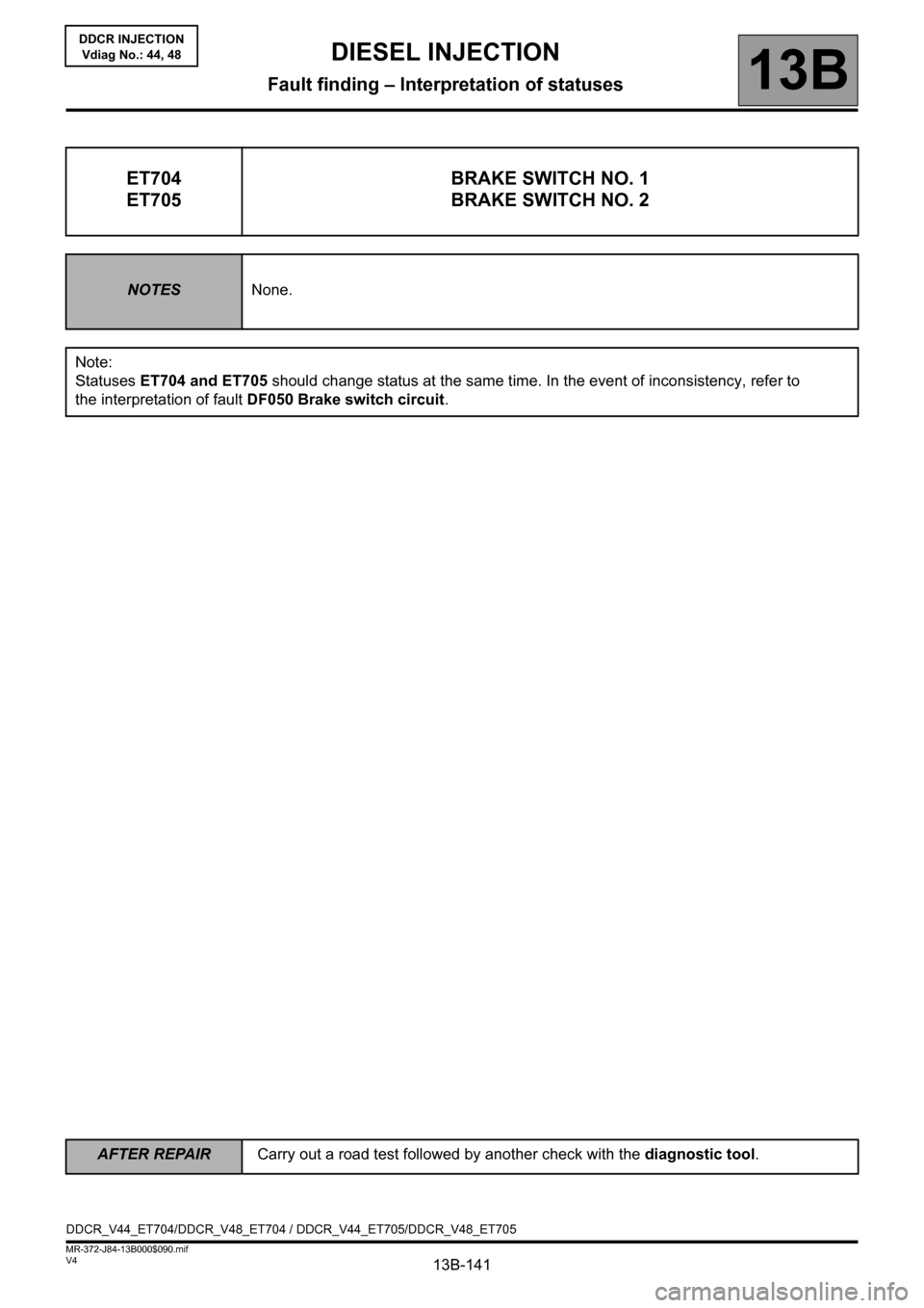
ET704
ET705BRAKE SWITCH NO. 1
BRAKE SWITCH NO. 2
NOTESNone.
Note:
Statuses ET704 and ET705 should change status at the same time. In the event of inconsistency, refer to
the interpretation of fault DF050 Brake switch circuit.
DDCR_V44_ET704/DDCR_V48_ET704 / DDCR_V44_ET705/DDCR_V48_ET705
Page 142 of 198

13B-142
AFTER REPAIRCarry out a road test followed by another check with the diagnostic tool.
V4 MR-372-J84-13B000$090.mif
DIESEL INJECTION
Fault finding – Interpretation of statuses13B
DDCR INJECTION
Vdiag No.: 44, 48
ET704
ET705
CONTINUED
ACTIVE
OR
INACTIVE
If the brake lights are working:
check the continuity and the absence of interference resistance on the following
connection:
– connection code 5A between components 160 and 120, 645, 119.
If there is a repair procedure (see Technical Note 6015A, Repairing electrical
wiring, Wiring: Precautions for repair) repair the wiring, otherwise replace it.
If the brake lights are not operational, check:
– the condition and fitting of the brake switch,
– the condition and conformity of the brake light fuse,
– the conformity of the values in the following table:
disconnect the switch and carry out the following checks:
for MEGANE II and SCENIC II with ESP
Continuity between
connectionsInsulation between
connections
Switch engaged
(Brake pedal released)5A and BPT 65G and SP17
Switch released
(Brake pedal depressed)65G and SP17 5A and BPT
For MEGANE II and SCENIC II without ESP
Continuity between
connectionsInsulation between
connections
Switch engaged
(Brake pedal released)5A and BPT 65G and SP17
Switch released
(Brake pedal depressed)65G and SP17 5A and BPT
Replace the switch if the values obtained are not correct.
Page 143 of 198

13B-143V4 MR-372-J84-13B000$100.mif
13B
DDCR INJECTION
Vdiag No.: 44, 48
* Heat.: HeatingTool parameter DIAGNOSTIC TOOL DESCRIPTION
PR005 EGR valve opening setpoint
PR008 Rail pressure set point
PR009 Turbocharging pressure setpoint
PR010 Idle speed regulation setpoint
PR017 Fuel flow
PR073 Air flowmeter supply voltage
PR028 Pedal position (gang 1)
PR029 Pedal position (gang 2)
PR030 Accelerator pedal position
PR032 Inlet pressure
PR035 Atmospheric pressure
PR037 Refrigerant pressure
PR038 Rail pressure
PR051 EGR valve position feedbac
PR055 Engine speed
PR059 Inlet air temperature (invalid in K9K 728)
PR061 External air temperature
PR063 Fuel temperature
PR064 Coolant temperature
PR074 Battery voltage
PR077 EGR valve position sensor voltage
PR080 Rail pressure sensor voltage
PR081 Inlet temperature sensor voltage
PR088 Pedal potentiometer gang 2 voltage
PR089 Vehicle speed
PR125 Power absorbed by air conditioning compressor
PR127 Heat.* resistor maximum authorised power
PR130 Cruise control setpoint
PR132 Air flow
DIESEL INJECTION
Fault finding – Parameter summary table
Page 144 of 198
13B-144V4 MR-372-J84-13B000$110.mif
13B
DDCR INJECTION
Vdiag No.: 44, 48
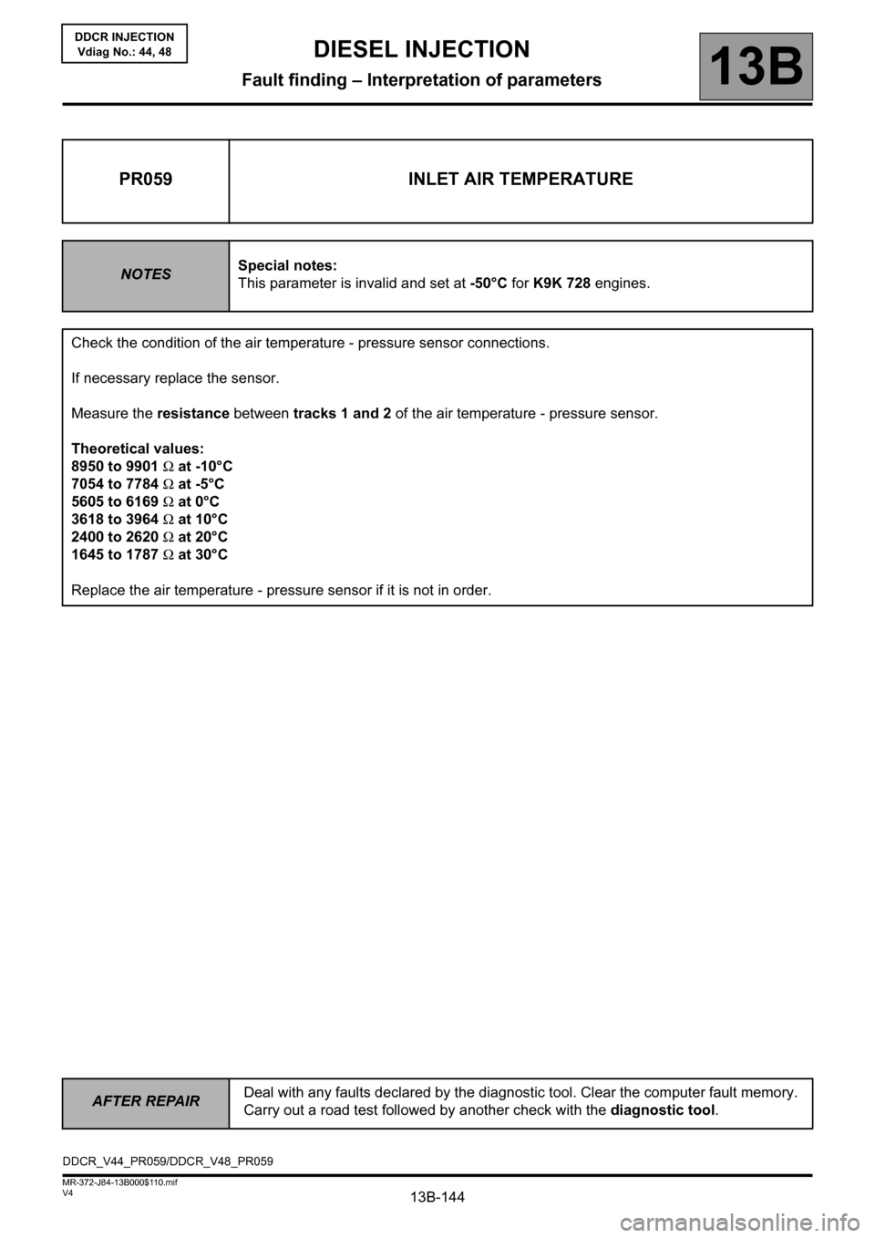
PR059 INLET AIR TEMPERATURE
NOTESSpecial notes:
This parameter is invalid and set at -50°C for K9K 728 engines.
Check the condition of the air temperature - pressure sensor connections.
If necessary replace the sensor.
Measure the resistance between tracks 1 and 2 of the air temperature - pressure sensor.
Theoretical values:
8950 to 9901 Ω at -10°C
7054 to 7784 Ω at -5°C
5605 to 6169 Ω at 0°C
3618 to 3964 Ω at 10°C
2400 to 2620 Ω at 20°C
1645 to 1787 Ω at 30°C
Replace the air temperature - pressure sensor if it is not in order.
DDCR_V44_PR059/DDCR_V48_PR059
DIESEL INJECTION
Fault finding – Interpretation of parameters
AFTER REPAIRDeal with any faults declared by the diagnostic tool. Clear the computer fault memory.
Carry out a road test followed by another check with the diagnostic tool.
Page 145 of 198
13B-145V4 MR-372-J84-13B000$110.mif
DIESEL INJECTION
Fault finding – Interpretation of parameters13B
DDCR INJECTION
Vdiag No.: 44, 48
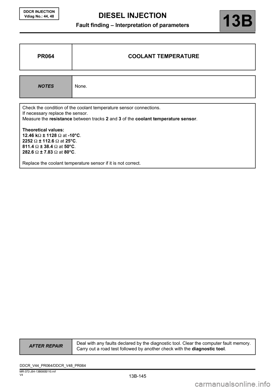
PR064 COOLANT TEMPERATURE
NOTESNone.
Check the condition of the coolant temperature sensor connections.
If necessary replace the sensor.
Measure the resistance between tracks 2 and 3 of the coolant temperature sensor.
Theoretical values:
12.46 kΩ ± 1128 Ω at -10°C.
2252 Ω ± 112.6 Ω at 25°C.
811.4 Ω ± 38.4 Ω at 50°C.
282.6 Ω ± 7.83 Ω at 80°C.
Replace the coolant temperature sensor if it is not correct.
DDCR_V44_PR064/DDCR_V48_PR064
AFTER REPAIRDeal with any faults declared by the diagnostic tool. Clear the computer fault memory.
Carry out a road test followed by another check with the diagnostic tool.
Page 146 of 198

13B-146V4 MR-372-J84-13B000$110.mif
DIESEL INJECTION
Fault finding – Interpretation of parameters13B
DDCR INJECTION
Vdiag No.: 44, 48
CLEARING
RZ001: fault memory.
This command is used to clear stored faults from the computer's memory.
RZ002: EGR adaptives.
Run this command only when replacing the EGR valve.
RZ004: Pressure regulation parameters.
Run this command when replacing all 4 injectors at once. It enables you to reset the injector adaptive programs.
RZ005: Programming.
This command lets you reinitialise the entire computer configuration according to the vehicle.
COMMANDS
LPG - FUEL CIRCUIT tab
AC010: High-pressure pump.
This command lets you listen for the operation of the high pressure pump.
AC005 to AC008: Injectors of cylinders 1 to 4.
These commands let you listen for the injector on the selected cylinder.
AC028: Static test.
This command activates fault finding for the EGR and high pressure pump circuits.
AC029: High-pressure circuit seal check.
This command lets you check the high pressure circuit sealing after a procedure has been carried out.
AC212: New pump chamber filling.
Use this command only after replacing the high pressure pump (see High pressure pump replacement in
Replacement of components). This command is used to activate the pump repriming sequence.
IGNITION - PREHEATING tab
AC001: Preheating unit.
This command actuates the preheating unit to test the heater plug supply.
EMISSION CONTROL - OBD tab
AC002: EGR solenoid valve.
This command lets you listen to the mechanical operation of the EGR valve.
AC028: Static test.
This command activates fault finding for the EGR and high pressure pump circuits.
TURBO - INLET AIR CIRCUIT tab
AC004: Turbocharging solenoid valve.
This command lets you listen for the operation of the turbocharging solenoid valve.
Page 147 of 198
13B-147V4 MR-372-J84-13B000$120.mif
13B
DDCR INJECTION
Vdiag No.: 44, 48
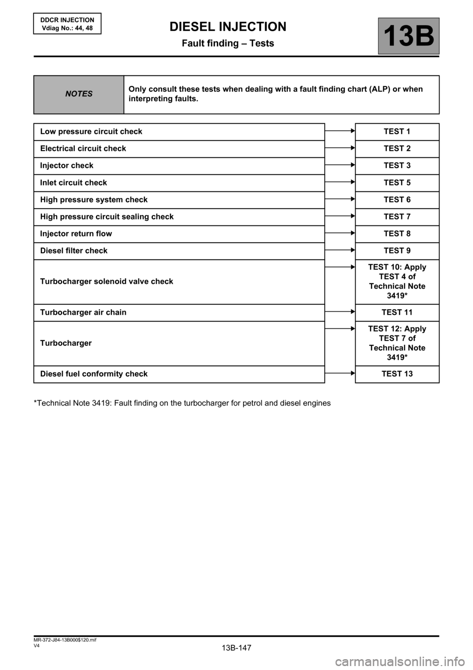
*Technical Note 3419: Fault finding on the turbocharger for petrol and diesel engines
NOTESOnly consult these tests when dealing with a fault finding chart (ALP) or when
interpreting faults.
Low pressure circuit check TEST 1
Electrical circuit checkTEST 2
Injector checkTEST 3
Inlet circuit checkTEST 5
High pressure system check TEST 6
High pressure circuit sealing check TEST 7
Injector return flowTEST 8
Diesel filter checkTEST 9
Turbocharger solenoid valve checkTEST 10: Apply
TEST 4 of
Technical Note
3419*
Turbocharger air chainTEST 11
TurbochargerTEST 12: Apply
TEST 7 of
Technical Note
3419*
Diesel fuel conformity check TEST 13
DIESEL INJECTION
Fault finding – Tests
Page 148 of 198
13B-148V4 MR-372-J84-13B000$120.mif
DIESEL INJECTION
Fault finding – Tests13B
DDCR INJECTION
Vdiag No.: 44, 48
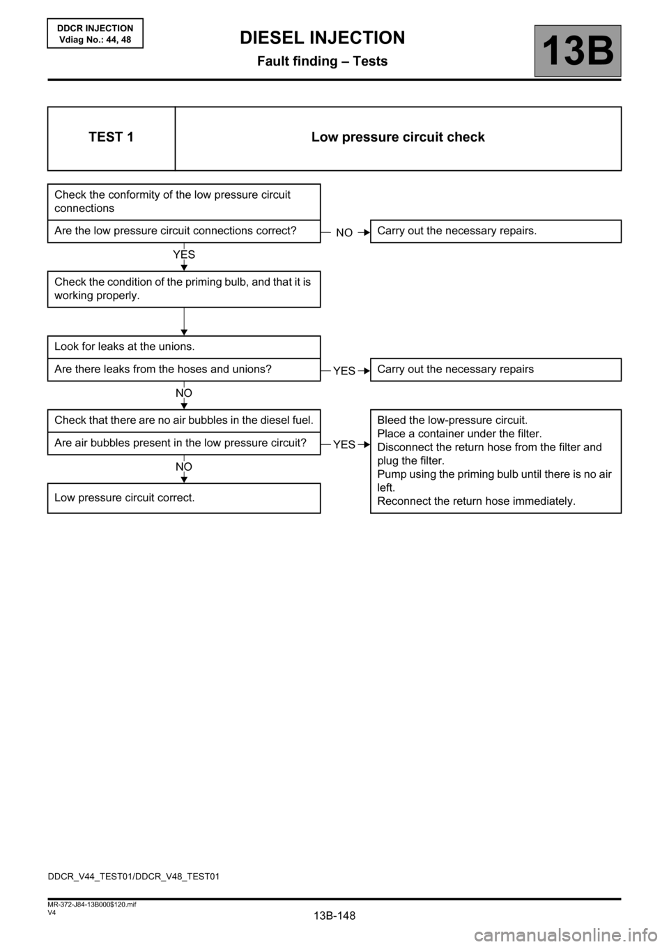
TEST 1 Low pressure circuit check
Check the conformity of the low pressure circuit
connections
Are the low pressure circuit connections correct? Carry out the necessary repairs.
Check the condition of the priming bulb, and that it is
working properly.
Look for leaks at the unions.
Are there leaks from the hoses and unions? Carry out the necessary repairs
Check that there are no air bubbles in the diesel fuel. Bleed the low-pressure circuit.
Place a container under the filter.
Disconnect the return hose from the filter and
plug the filter.
Pump using the priming bulb until there is no air
left.
Reconnect the return hose immediately. Are air bubbles present in the low pressure circuit?
Low pressure circuit correct.
NO
YES
YES
NO
YES
NO
DDCR_V44_TEST01/DDCR_V48_TEST01
Page 149 of 198
13B-149V4 MR-372-J84-13B000$120.mif
DIESEL INJECTION
Fault finding – Tests13B
DDCR INJECTION
Vdiag No.: 44, 48
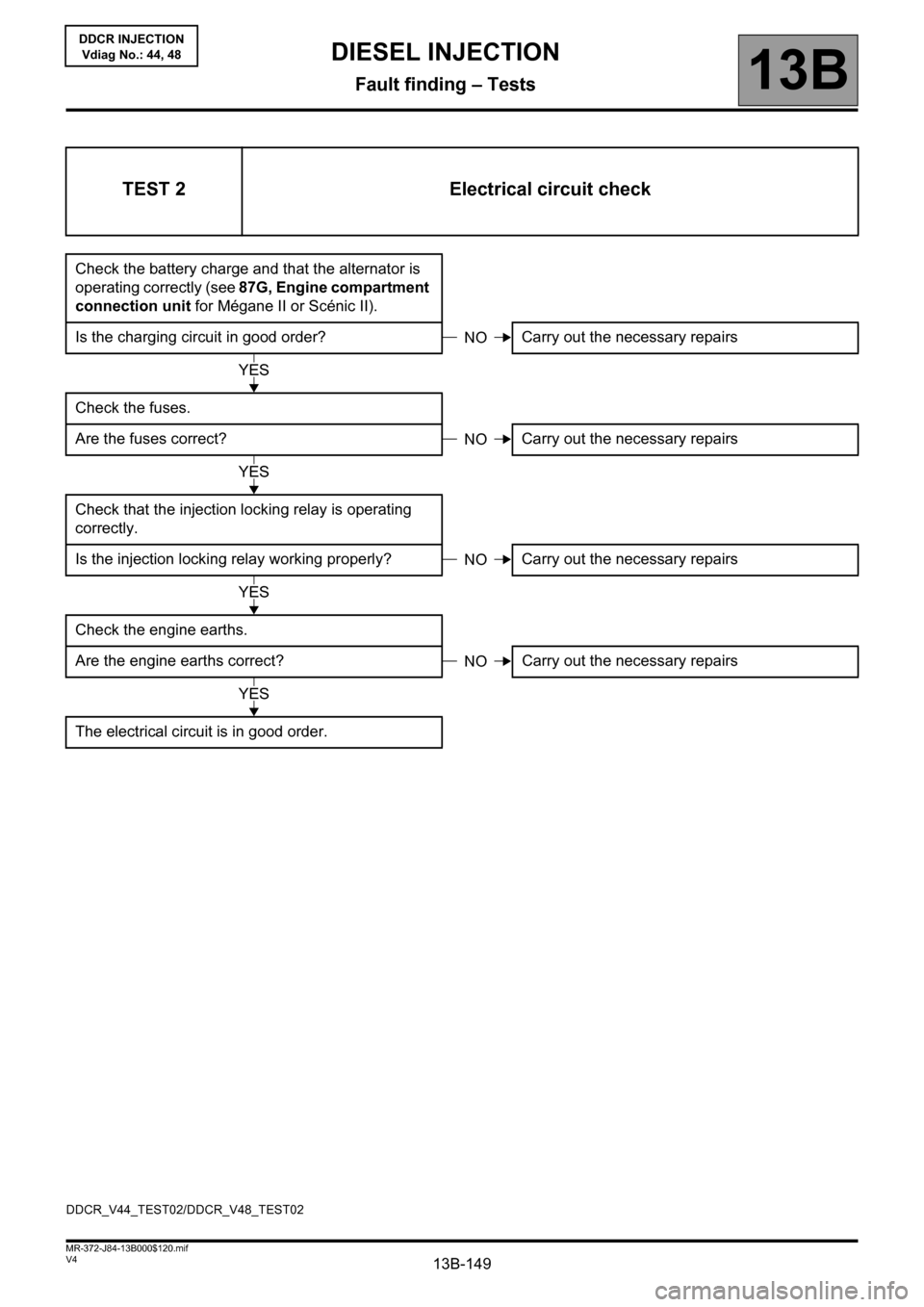
TEST 2 Electrical circuit check
Check the battery charge and that the alternator is
operating correctly (see 87G, Engine compartment
connection unit for Mégane II or Scénic II).
Is the charging circuit in good order? Carry out the necessary repairs
Check the fuses.
Are the fuses correct? Carry out the necessary repairs
Check that the injection locking relay is operating
correctly.
Is the injection locking relay working properly? Carry out the necessary repairs
Check the engine earths.
Are the engine earths correct?Carry out the necessary repairs
The electrical circuit is in good order.
NO
YES
NO
YES
NO
YES
NO
YES
DDCR_V44_TEST02/DDCR_V48_TEST02
Page 150 of 198
13B-150V4 MR-372-J84-13B000$120.mif
DIESEL INJECTION
Fault finding – Tests13B
DDCR INJECTION
Vdiag No.: 44, 48
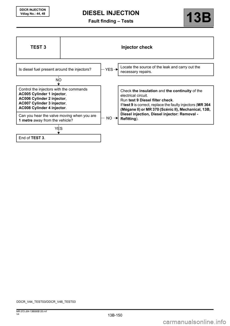
TEST 3 Injector check
Is diesel fuel present around the injectors?Locate the source of the leak and carry out the
necessary repairs.
Control the injectors with the commands
AC005 Cylinder 1 injector,
AC006 Cylinder 2 injector,
AC007 Cylinder 3 injector,
AC008 Cylinder 4 injector.Check the insulation and the continuity of the
electrical circuit.
Run test 9 Diesel filter check.
If test 9 is correct, replace the faulty injectors (MR 364
(Mégane II) or MR 370 (Scénic II), Mechanical, 13B,
Diesel injection, Diesel injector: Removal -
Refitting). Can you hear the valve moving when you are
1metre away from the vehicle?
End of TEST 3.YES
NO
NO
YES
DDCR_V44_TEST03/DDCR_V48_TEST03