Seat Alhambra 2011 Owner's Manual
Manufacturer: SEAT, Model Year: 2011, Model line: Alhambra, Model: Seat Alhambra 2011Pages: 385, PDF Size: 7.92 MB
Page 331 of 385
329
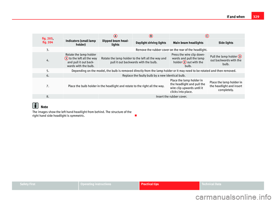
If and when fig. 203,
fig. 204 A B C
Indicators (small lamp
holder) Dipped beam head-
lights Daylight driving lights Main beam headlights Side lights
3. Remove the rubber cover on the rear of the headlight.
4. Rotate the lamp holder
1 to the left all the way
and pu l
l it out back-
wards with the bulb. Rotate the lamp holder to the left all the way and
pul
l it out backwards with the bulb. Press the wire clip down-
war d
s and pull the lamp
holder 2 out with the
bu l
b. Pull the lamp holder
3 out backwards with the
bul
b. 5. Depending on the model, the bulb is removed directly from the lamp holder or it may need to be rotated and then removed.
6. Replace the faulty bulb by a new identical bulb.
7. Place the bulb holder in the headlight and rotate to the right all the way. Place the lamp holder in
the hea
dlight
and pull the
wire clip upwards until it
clicks into place. Place the lamp holder in
the hea dlight
and insert
completely. 8. Insert the rubber cover.
Note
The images show the left hand headlight from behind. The structure of the
right h and s
ide headlight is symmetric. Safety First Operating instructions Practical tips Technical Data
Page 332 of 385
330
If and when
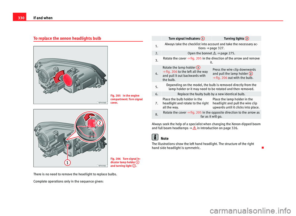
To replace the xenon headlights bulb Fig. 205 In the engine
comp
ar
tment: Turn signal
cover. Fig. 206 Turn signal in-
dicat
or l
amp holder 1 and turning light
2 .
There is no need to remove the headlight to replace bulbs.
Comp l
ete operations only in the sequence given: Turn signal indicators
1 Turning lights
2 1. Always take the checklist into account and take the necessary ac-
tions ⇒
page 327. 2. Open the bonnet
⇒ page 275. 3. Rotate the cover ⇒
fig. 205 in the dir
ection of the arrow and remove
it. 4. Rotate the lamp holder
1 ⇒ fig. 206 to the left all the way
and p
u
ll it out backwards with
the bulb. Press the wire clip downwards
and pu
l
l the lamp holder 2 ⇒ fig. 206 out w
ith the b
ulb. 5. Depending on the model, the bulb is removed directly from the
lamp ho l
der or it may need to be rotated and then removed. 6. Replace the faulty bulb by a new identical bulb.
7. Place the bulb holder in the
hea
dlight
and rotate to the right
all the way. Place the lamp holder in the
hea
dlight
and pull the wire clip
upwards until it clicks into place. 8. Rotate the cover ⇒
fig. 205 in the op
posite direction to the arrow as
far as it will go. Always seek the help of a specialist when changing the Xenon dipped beam
and fu
l
l beam headlamps ⇒ in Introduction on page 326.
Note
The illustrations show the left hand headlight. The structure of the right
hand s ide he
adlight is symmetric.
Page 333 of 385
331
If and when
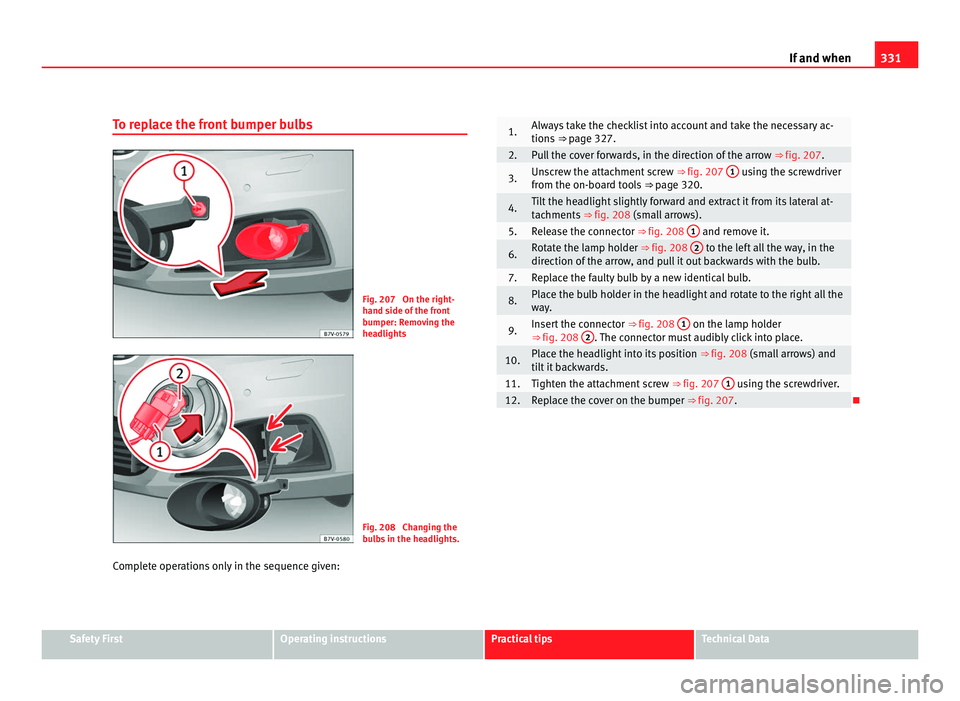
To replace the front bumper bulbs Fig. 207 On the right-
hand s
ide of
the front
bumper: Removing the
headlights Fig. 208 Changing the
bu
l
bs in the headlights.
Complete operations only in the sequence given: 1. Always take the checklist into account and take the necessary ac-
tions
⇒
page 327. 2. Pull the cover forwards, in the direction of the arrow
⇒ fig. 207. 3. Unscrew the attachment screw
⇒ fig. 207 1 using the screwdriver
from the on-bo ar
d tools ⇒ page 320. 4. Tilt the headlight slightly forward and extract it from its lateral at-
tac
hments
⇒ fig. 208 (small arrows). 5. Release the connector ⇒ fig. 208
1 and remove it.
6. Rotate the lamp holder ⇒ fig. 208
2 to the left all the way, in the
direction of the arr
ow, and pull it out backwards with the bulb. 7. Replace the faulty bulb by a new identical bulb.
8. Place the bulb holder in the headlight and rotate to the right all the
wa
y
. 9. Insert the connector
⇒ fig. 208 1 on the lamp holder
⇒ fig. 208 2 . The connector must audibly click into place.
10. Place the headlight into its position
⇒ fig. 208 (small
arrows) and
tilt it backwards. 11. Tighten the attachment screw
⇒ fig. 207 1 using the screwdriver.
12. Replace the cover on the bumper ⇒ fig. 207.
Safety First Operating instructions Practical tips Technical Data
Page 334 of 385
332
If and when
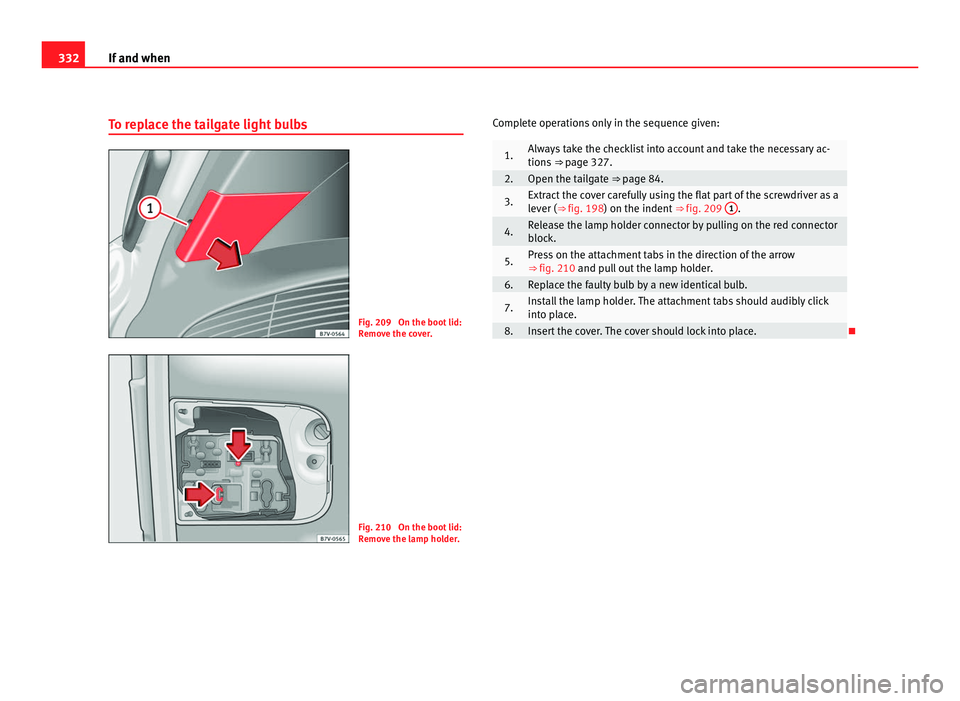
To replace the tailgate light bulbs Fig. 209 On the boot lid:
Remo
v
e the cover. Fig. 210 On the boot lid:
Remo
v
e the lamp holder. Complete operations only in the sequence given: 1. Always take the checklist into account and take the necessary ac-
tions
⇒
page 327. 2. Open the tailgate ⇒ pag
e 84. 3. Extract the cover carefully using the flat part of the screwdriver as a
lev
er (
⇒ fig. 198) on the indent ⇒ fig. 209 1 .
4. Release the lamp holder connector by pulling on the red connector
bloc
k. 5. Press on the attachment tabs in the direction of the arrow
⇒ fig. 210 and pu
l
l out the lamp holder. 6. Replace the faulty bulb by a new identical bulb.
7. Install the lamp holder. The attachment tabs should audibly click
into p
l
ace. 8. Insert the cover. The cover should lock into place.
Page 335 of 385
333
If and when
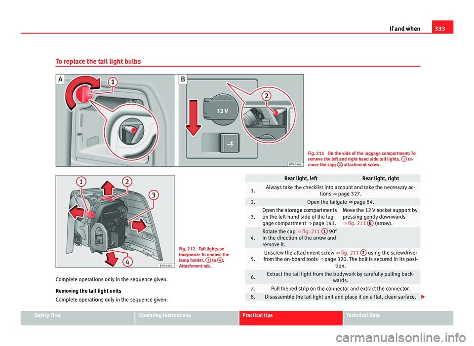
To replace the tail light bulbs Fig. 211 On the side of the luggage compartment: To
remo
v
e the left and right hand side tail lights. 1 re-
mov e the c
ap; 2 attachment screw.
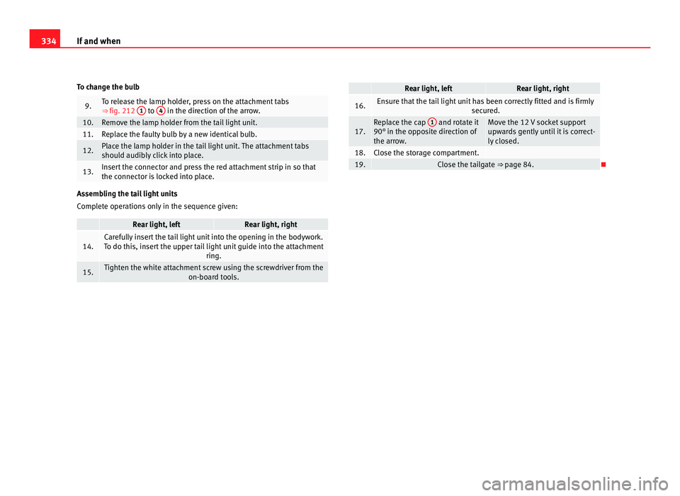
Fig. 212 Tail lights on
bodywork:
T
o remove the
lamp holder. 1 to
4 :
Attac hment
tab.
Complete operations only in the sequence given.
Remov
ing the tail light units
Complete operations only in the sequence given: Rear light, left Rear light, right
1. Always take the checklist into account and take the necessary ac-
tions ⇒
page 327. 2. Open the tailgate ⇒ pag
e 84. 3. Open the storage compartments
on the lef
t
-hand side of the lug-
gage compartment ⇒ page 141. Move the 12 V socket support by
pre
s
sing gently downwards
⇒ fig. 211 B (arrow).
4. Rotate the cap ⇒ fig. 211
1 90°
in the direction of the arr
ow and
remove it.
5. Unscrew the attachment screw
⇒ fig. 211 2 using the screwdriver
from the on-bo ar
d tools ⇒ page 320. The bolt is secured in its posi-
tion. 6. Extract the tail light from the bodywork by carefully pulling back-
ward
s. 7. Pull the red strip on the connector and extract the connector.
8. Disassemble the tail light unit and place it on a flat, clean surface.
Safety First Operating instructions Practical tips Technical Data
Page 336 of 385
334
If and when
To change the bulb 9. To release the lamp holder, press on the attachment tabs
⇒ fig. 212
1 to
4 in the direction of the arrow.
10. Remove the lamp holder from the tail light unit.
11. Replace the faulty bulb by a new identical bulb.
12. Place the lamp holder in the tail light unit. The attachment tabs
shoul
d audib
ly click into place. 13. Insert the connector and press the red attachment strip in so that
the connect
or i
s locked into place.Assembling the tail light units
Comp
l
ete operations only in the sequence given: Rear light, left Rear light, right
14. Carefully insert the tail light unit into the opening in the bodywork.
To do thi s, in
sert the upper tail light unit guide into the attachment ring.15. Tighten the white attachment screw using the screwdriver from the
on-board t
ools. Rear light, left Rear light, right
16. Ensure that the tail light unit has been correctly fitted and is firmly
secured. 17. Replace the cap
1 and rotate it
90° in the oppo s
ite direction of
the arrow. Move the 12 V socket support
upw
ar
ds gently until it is correct-
ly closed. 18. Close the storage compartment.
19. Close the tailgate ⇒
pag
e 84.
Page 337 of 385
335
If and when
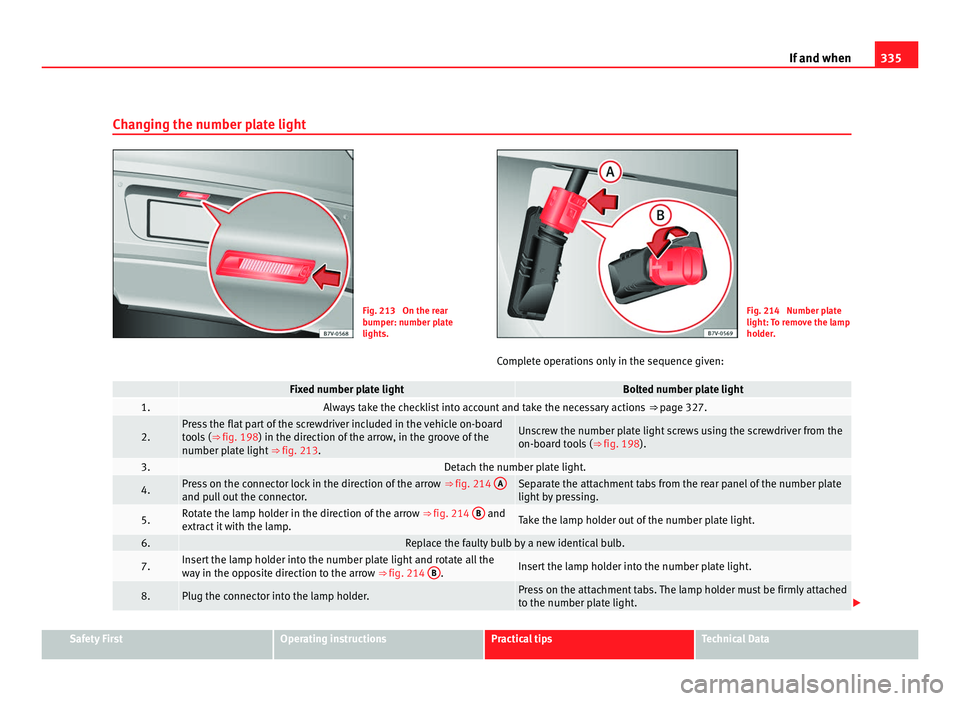
Changing the number plate light Fig. 213 On the rear
bumper: number p
l
ate
lights. Fig. 214 Number plate
light: T
o r
emove the lamp
holder.
Complete operations only in the sequence given: Fixed number plate light Bolted number plate light
1. Always take the checklist into account and take the necessary actions
⇒ page 327. 2. Press the flat part of the screwdriver included in the vehicle on-board
too
l
s (⇒ fig. 198) in the direction of the arrow, in the groove of the
number plate light ⇒ fig. 213. Unscrew the number plate light screws using the screwdriver from the
on-boar
d t
ools (⇒ fig. 198). 3. Detach the number plate light.
4. Press on the connector lock in the direction of the arrow
⇒ fig. 214 A and pull out the connector. Separate the attachment tabs from the rear panel of the number plate
light b
y
pressing. 5. Rotate the lamp holder in the direction of the arrow
⇒ fig. 214 B and
extr act
it with the lamp. Take the lamp holder out of the number plate light.
6. Replace the faulty bulb by a new identical bulb.
7. Insert the lamp holder into the number plate light and rotate all the
wa
y
in the opposite direction to the arrow ⇒ fig. 214 B . Insert the lamp holder into the number plate light.
8. Plug the connector into the lamp holder. Press on the attachment tabs. The lamp holder must be firmly attached
to the number p
l
ate light. Safety First Operating instructions Practical tips Technical Data
Page 338 of 385
336
If and when Fixed number plate light Bolted number plate light
9. Insert the number plate light carefully into the opening on the bumper. Ensure that the number plate light is in the correct position.
10. Insert the number plate light into the bumper until it audibly clicks into
pl
ac
e. Tighten the attachment screws for the number plate light using the
sc
r
ewdriver.
Page 339 of 385
337
If and when
Starting assistance
Introduction If the engine fails to start because of a discharged battery, the battery of an-
other v
ehic
le can be used to start the engine. Before starting, check the
magic eye on the battery ⇒ page 288.
For starting assistance, jump lead cables conforming to the standard
DIN 72553 are required (see the cable manufacturer instructions). The jump
lead cable must be at least 25 mm 2
in section (0.038 inches 2
) for petrol en-
gines, and 35 mm 2
(0.054 inches 2
) for diesel engines.
For vehicles whose battery is not in the engine compartment, the jump
leads should only be connected to the starting assistance connection
points in the engine compartment.
Additional information and warnings:
● Starter assist systems (Start-Stop function) ⇒ pag
e 194
● Working in the engine compartment ⇒ pag
e 275
● Selective Catalytic Reduction (AdBlue) ⇒ pag
e 271
● Vehicle battery ⇒ pag
e 288 WARNING
Incorrect use of jump leads and incorrectly jump starting could cause the
batt er
y to explode resulting in serious injury. Please observe the follow-
ing rules to minimise the risk of a battery explosion:
● All work involving the vehicle battery and electrical system can cause
corro
sion, fire and serious electric shocks. Always read and take into ac-
count the safety warnings and standards before beginning work on the
battery ⇒ page 288, Vehicle battery. WARNING (Continued)
● The b attery providing current must have the same voltage (12V) and
ap pr
oximately the same capacity (see markings on battery) as the flat
battery.
● Never charge a frozen or recently thawed battery. A flat battery can
freeze at
temperatures around 0°C (+32°F).
● If a battery is frozen and/or has been frozen then it must be replaced.
● A highly explosive mixture of gases is released when the battery is
being ch
arged. Always keep lit cigarettes, open flames, sparks and fire
far from the battery. Never use a mobile telephone when connecting and
removing the jump leads.
● Charge the battery only in well ventilated areas given that when the
batter
y is charged by outside assistance, it creates a mix of highly explo-
sive gases.
● Jump leads should never enter into contact with moving parts in the
engine comp
artment.
● Never switch the positive and negative poles or connect the jump
lea
ds incorrectly.
● Note the instructions provided by the manufacturer of the jump leads. CAUTION
To avoid considerable damage to the vehicle electrical system, note the fol-
low in
g carefully:
● If the jump leads are incorrectly connected, this could result in a short
circ
uit.
● The vehicles must not touch each other, otherwise electricity could flow
as soon a
s the positive terminals are connected. Safety First Operating instructions Practical tips Technical Data
Page 340 of 385
338
If and when
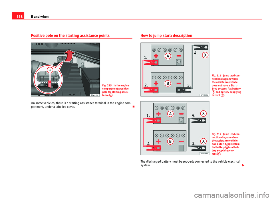
Positive pole on the starting assistance points Fig. 215 In the engine
comp
ar
tment: positive
pole for starting assis-
tance + .
On some vehicles, there is a starting assistance terminal in the engine com-
par tment, u
nder a labelled cover. How to jump start: description Fig. 216 Jump lead con-
nection diagr
am when
the a
ssistance vehicle
does not have a Start-
Stop system: flat battery A and battery supplying
curr ent
B .
Fig. 217 Jump lead con-
nection diagr
am when
the a
ssistance vehicle
has a Start-Stop system:
flat battery A and bat-
ter y
supplying cur-
rent B .
The discharged battery must be properly connected to the vehicle electrical
sys t
em.