Seat Alhambra 2011 Owner's Manual
Manufacturer: SEAT, Model Year: 2011, Model line: Alhambra, Model: Seat Alhambra 2011Pages: 385, PDF Size: 7.92 MB
Page 311 of 385
309
Wheels and tyres
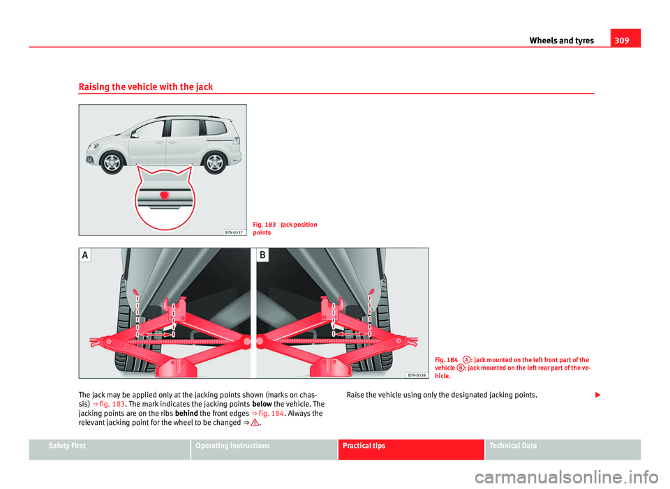
Raising the vehicle with the jack Fig. 183 Jack position
points
Fig. 184
A : jack mounted on the left front part of the
vehic l
e B : jack mounted on the left rear part of the ve-
hicl e.
The j
ack may be applied only at the jacking points shown (marks on chas-
sis)
⇒ fig. 183. The mark indicates the jacking points below the vehicle. The
jacking points are on the ribs behind the front edges ⇒ fig. 184. Always the
relevant jacking point for the wheel to be changed ⇒ .
Raise the vehicle using only the designated jacking points.
Safety First Operating instructions Practical tips Technical Data
Page 312 of 385
310
Wheels and tyres
Check list
For y
our own safety and that of other passengers, the following points
should be observed in the order given ⇒ :
Select a s
uitable flat and firm surface for raising the vehicle.
Switch off the engine, engage a gear (manual gearbox) or place the se-
lector lever in position P ⇒ page 174 and turn on the electronic parking
brake ⇒ page 183.
When towing a trailer: unhook the trailer from the towing vehicle and
park it correctly.
Loosen the wheel bolts on the wheel to be changed ⇒ page 307.
Look below the vehicle for the jacking point ⇒ fig. 183 closest to the
tyre which has to be changed.
Raise the jack with the handle until it can be inserted below the jacking
point.
Ensure that the foot of the jack is firmly on the ground and that it is
placed immediately below the lifting point on the vehicle ⇒ fig. 184.
Straighten the jack and continue raising it using the handle until the
claw holds the vertical reinforcement beneath the vehicle ⇒ fig. 184.
Raise the vehicle until the wheel is clear of the ground. WARNING
If the vehicle is not correctly raised, it could fall off the jack causing seri-
ous injur
y. Please observe the following rules to minimise the risk of in-
jury:
● You should only use a jack approved by SEAT for your vehicle. Other
jack
s, even those approved for other SEAT models, might slip out of
place.
● The ground should be firm and flat. If the ground is sloped or soft
then the vehic
le could slip and fall off the jack. If necessary, support the
jack on a wide solid base. 1.
2.
3.
4.
5.
6.
7.
8.
9. WARNING (Continued)
● If the ground is slippery (for example, on tiles), place a non-slip sur-
f ac
e (for example a floor mat) beneath the jack to avoid slipping.
● Only fit the jack at the prescribed jacking points. The claw of the jack
should grip the r
einforcement nerve on the underbody ⇒ fig. 184.
● You should never have any limbs beneath a raised vehicle which is
only s
upported by a jack.
● If you have to work underneath the vehicle, you must use suitable
stand
s additionally to support the vehicle, there is a risk of accident!.
● Never raise the vehicle if it is tilting to one side or the engine is run-
ning.
● Never s
tart the engine when the vehicle is raised. The vehicle may
come loose fr
om the jack due to the engine vibrations. WARNING
Failure to follow the checklist prepared for your own safety could lead to
acc ident
s and severe injuries.
● Always complete the operations given in the checklist and observe
the genera
l rules of safety.
Page 313 of 385
311
Wheels and tyres
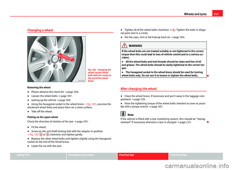
Changing a wheel Fig. 185 Changing the
wheel: loosen wheel
bo
lt
s with the socket at
the end of the wheel
brace.
Removing the wheel
● Please observe the check list ⇒ page 306.
● L
oosen the wheel bolts ⇒ page 307.
● Jac
king up the vehicle ⇒ page 309.
● U
sing the hexagonal socket in the wheel brace ⇒ fig. 185, uns
crew the
slackened wheel bolts and place them on a clean surface.
● Take off the wheel.
Putting on the s
pare wheel
Check the direction of rotation of the tyre ⇒ page 295.
● Fit the wheel.
● Screw on the anti-theft locking bolt with the adapter in position
⇒ fig. 182 2 or
3 clockwise and tighten gently.
● Replace the other wheel bolts and tighten slightl
y using the hexagonal
socket on the end of the wheel brace.
● Lower the car with the jack. ●
Tighten all of the wheel bolts clockwise ⇒ . Tighten the bolts in diago-
nal p
airs (not in a circle).
● Put the caps, trim or full hubcap back on ⇒ page 304. WARNING
If the wheel bolts are not treated suitably or not tightened to the correct
tor que then thi
s could lead to loss of vehicle control and to a serious ac-
cident.
● All the wheel bolts and hub threads should be clean and free of oil
and grea
se. The wheel bolts should be easily tightened to the correct tor-
que.
● The hexagonal socket in the wheel brace should be used for turning
wheel bolt
s only. Do not use it to loosen or tighten the wheel bolts.
After changing the wheel ●
Clean the wheel brace, if necessary and put it away in the luggage com-
par tment
⇒ page 320.
● Have the tightening torque of the wheel bolts checked as soon as possi-
ble w
ith a torque wrench ⇒ page 307. Note
If the vehicle is fitted with a tyre monitoring system, this should be “reprog-
rammed” if nec
essary whenever a tyre is changed ⇒ page 223.Safety First Operating instructions Practical tips Technical Data
Page 314 of 385
312
If and when
If and when
In case of emergency
Introduction Additional information and warnings:
●
Braking, stopping and parking ⇒ pag e 183
● Emer
gency locking and unlocking ⇒ page 314
● V
ehicle tools ⇒ page 320 WARNING
A faulty vehicle in traffic represents a risk of accident for the driver and
for other r o
ad users.
● Stop the vehicle safely as soon as possible. Park the vehicle a safe
dist
ance from surrounding traffic to lock all the doors in case of an emer-
gency. Turn on the hazard warning lights to warn other road users.
● Never leave children or disabled people alone in the vehicle if the
doors ar
e to be locked. In case of an emergency, passengers will be trap-
ped inside the vehicle. Individuals locked in the vehicle can be exposed
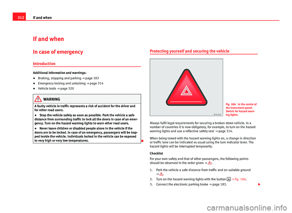
to very high or very low temperatures. Protecting yourself and securing the vehicle Fig. 186 In the centre of
the ins
trument
panel:
Switch for hazard warn-
ing lights.
Always fulfil legal requirements for securing a broken down vehicle. In a
number of cou
ntries it is now obligatory, for example, to turn on the hazard
warning lights and use a reflective safety vest ⇒ page 314.
When being towed with the hazard warning lights on, a change in direction
or traffic lane can be indicated as usual using the turn indicator lever. The
hazard lights will be interrupted temporarily.
Checklist
For your own safety and that of other passengers, the following points
should be observed in the order given ⇒ :
Park the
vehicle a safe distance from traffic and on suitable ground
⇒ .
Turn on the h az
ard warning lights with the button ⇒
fig. 186 .
C
onnect the electronic parking brake ⇒ page 183.
1.
2.
3.
Page 315 of 385
313
If and when
Move the selector lever to its intermediate position or to P ⇒ page 174.
St op the engine and remove the key from the ignition ⇒ page 170.
Have all occupants leave the vehicle and move to safety, for example
behind a guard rail.
When leaving the vehicle, take all keys with you.
Place an emergency warning triangle to indicate the position of your ve-
hicle to other road users.
Allow the engine to cool and check if a specialist is required.
Examples of when to use the hazard warning lights:
● If the vehicles ahead suddenly slow down or reach the end of a traffic
jam, to w
arn the vehicles behind.
● In case of an emergency.
● If the vehicle breaks down.
● When being towed.
Alwa
ys comply with the applicable laws regarding the use of hazard warn-
ing lights.
If the hazard warning lights are not working, you must use an alternative
method of drawing attention to your vehicle. This method must comply with
traffic legislation. WARNING
Failure to follow the checklist prepared for your own safety could lead to
acc ident
s and severe injuries.
● Always complete the operations given in the checklist and observe
the genera
l rules of safety. 4.
5.
6.
7.
8.
9.
WARNING
The components of the exhaust system reach very high temperatures.
This c
ould cause a fire and considerable damage.
● Always park your vehicle so that no part of the exhaust system can
come in cont
act with flammable materials (such as dried grass or fuel). Note
● The vehicle battery will discharge and run down if the hazard warning
lights r
emain on for too much time (even with the ignition turned off).
● For some vehicles, the brake lights will blink when braking suddenly at
speeds
of approximately 80 km/h to warn vehicles behind. If braking con-
tinues, then the hazard warning lights will automatically be turned on at the
speed of less than approximately 10 km an hour. The brake lights remain lit.
Upon accelerating, the hazard warning lights will be automatically turned
off. Safety First Operating instructions Practical tips Technical Data
Page 316 of 385
314
If and when
First aid kit, warning triangle, reflective vests and fire
extingui
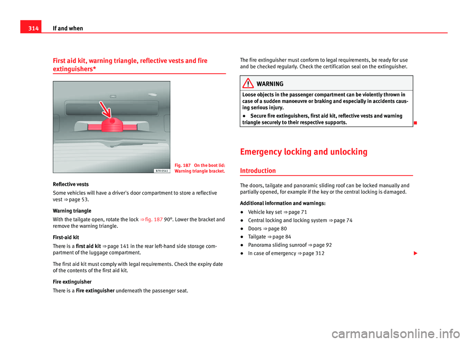
shers* Fig. 187 On the boot lid:
Warnin
g tri
angle bracket.
Reflective vests
Some vehic
les will have a driver's door compartment to store a reflective
vest ⇒ page 53.
Warning triangle
With the tailgate open, rotate the lock ⇒ fig. 187 90°. Lower the bracket and
remove the warning triangle.
First-aid kit
There is a first aid kit ⇒ page 141 in the rear left-hand side storage com-
partment of the luggage compartment.
The first aid kit must comply with legal requirements. Check the expiry date
of the contents of the first aid kit.
Fire extinguisher
There is a Fire extinguisher underneath the passenger seat. The fire extinguisher must conform to legal requirements, be ready for use
and be check
ed regularly. Check the certification seal on the extinguisher. WARNING
Loose objects in the passenger compartment can be violently thrown in
ca se of
a sudden manoeuvre or braking and especially in accidents caus-
ing serious injury.
● Secure fire extinguishers, first aid kit, reflective vests and warning
triangl
e securely to their respective supports.
Emergency locking and unlocking Introduction The doors, tailgate and panoramic sliding roof can be locked manually and
par
ti
ally opened, for example if the key or the central locking is damaged.
Additional information and warnings:
● Vehicle key set ⇒ pag
e 71
● Central locking and locking system ⇒ pag
e 74
● Doors ⇒ page 80
● T
ailgate ⇒ pag
e 84
● Panorama sliding sunroof ⇒ pag
e 92
● In case of emergency ⇒ pag
e 312
Page 317 of 385
315
If and when WARNING
Opening and closing doors carelessly can cause serious injury.
● If the vehicle is locked from outside, the doors and windows cannot
be opened from the in s
ide.
● Never leave children or disabled people alone in the car. They could
be trapped in the c
ar in an emergency and will not be able to get them-
selves to safety.
● Depending on the time of the year, temperatures inside a locked and
closed
vehicle can be extremely high or extremely low resulting in seri-
ous injuries and illness or even death, particularly for young children. WARNING
Getting in the way of the doors and the panoramic sliding roof is danger-
ous and c
an lead to serious injury.
● Open and close the doors and the panoramic sliding roof only when
nobody i
s in the way. CAUTION
When opening and closing in an emergency, carefully disassemble compo-
nents and then r e
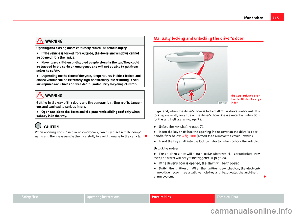
assemble them carefully to avoid damage to the vehicle. Manually locking and unlocking the driver's door Fig. 188 Driver's door
handl
e: Hid
den lock cyl-
inder.
In general, when the driver's door is locked all other doors are locked. Un-
lockin
g manually only opens the driver's door. Please note the instructions
for the antitheft alarm ⇒ page 74.
● Unfold the key shaft ⇒ page 71.
● In
sert the key shaft into the opening in the cover on the driver's door
handle fr
om below ⇒ fig. 188 (arrow) then remove the cover upwards.
● Insert the key shaft into the lock cylinder to unlock or lock the vehicle.
Unlock
ing notes:
● The antitheft alarm will remain active when vehicles are unlocked. How-
ever, the al
arm will not yet be triggered ⇒ page 74.
● If the driver's door is opened, the alarm will be triggered.
● Switch the ignition on. When the ignition is switched on, the electronic
immobi
liser recognises a valid vehicle key and deactivates the anti-theft
alarm system. Safety First Operating instructions Practical tips Technical Data
Page 318 of 385
316
If and when Note
The antitheft alarm is not activated when the vehicle is locked manually us-
ing the k ey
⇒ page 74.
Locking the passenger side door and sliding doors
manual
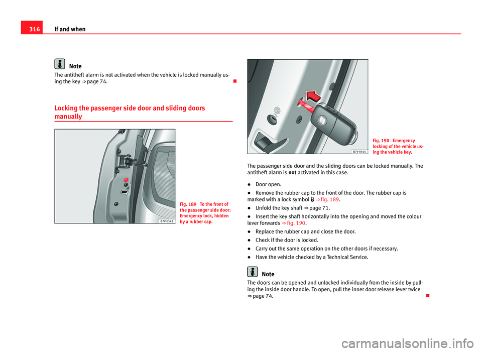
ly Fig. 189 To the front of
the pa
s
senger side door:
Emergency lock, hidden
by a rubber cap. Fig. 190 Emergency
lock
in
g of the vehicle us-
ing the vehicle key.
The passenger side door and the sliding doors can be locked manually. The
antitheft al
arm is not activated in this case.
● Door open.
● Remove the rubber cap to the front of the door. The rubber cap is
marked w
ith a lock symbol ⇒ fig. 189.
● Unfold the key shaft ⇒ page 71.
● In
sert the key shaft horizontally into the opening and moved the colour
lever f
orwards ⇒ fig. 190.
● Replace the rubber cap and close the door.
● Check if the door is locked.
● Carry out the same operation on the other doors if necessary.
● Have the vehicle checked by a Technical Service. Note
The doors can be opened and unlocked individually from the inside by pull-
ing the in s
ide door handle. To open, pull the inner door release lever twice
⇒ page 74.
Page 319 of 385
317
If and when
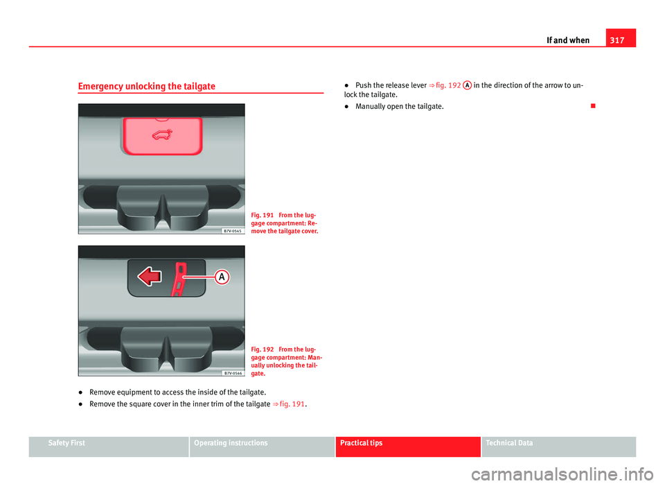
Emergency unlocking the tailgate Fig. 191 From the lug-
gag
e c
ompartment: Re-
move the tailgate cover. Fig. 192 From the lug-
gag
e c
ompartment: Man-
ually unlocking the tail-
gate.
● Remove equipment to access the inside of the tailgate.
● Remove the square cover in the inner trim of the tailgate ⇒ fig. 191.●
Push the release lever ⇒ fig. 192 A in the direction of the arrow to un-
lock the t
ailgate.
● Manually open the tailgate. Safety First Operating instructions Practical tips Technical Data
Page 320 of 385
318
If and when
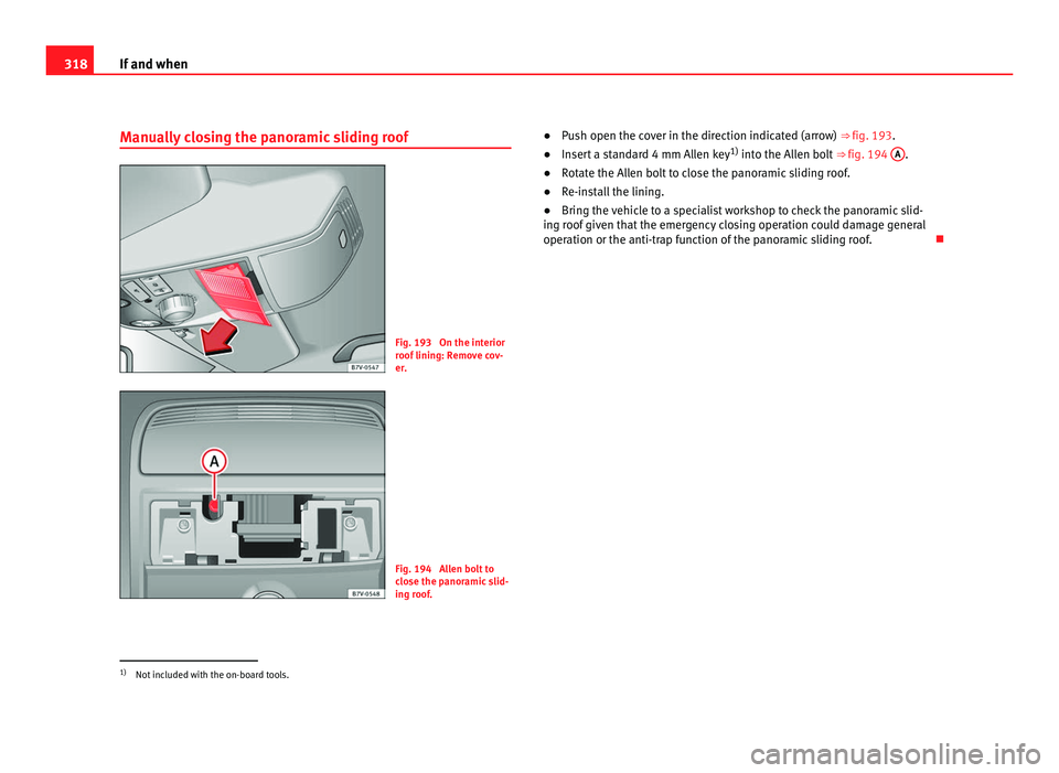
Manually closing the panoramic sliding roof Fig. 193 On the interior
roof
linin
g: Remove cov-
er. Fig. 194 Allen bolt to
clo
se the p
anoramic slid-
ing roof. ●
Push open the cover in the direction indicated (arrow) ⇒ fig. 193.
● Inser
t a standard 4 mm Allen key 1)
into the Al
len bolt ⇒ fig. 194 A .
● Rotate the Allen bolt to close the panoramic sliding roof.
● Re-install the lining.
● Bring the vehicle to a specialist workshop to check the panoramic slid-
ing r oof
given that the emergency closing operation could damage general
operation or the anti-trap function of the panoramic sliding roof. 1)
Not included with the on-board tools.