torque SSANGYONG KORANDO 1997 Service Repair Manual
[x] Cancel search | Manufacturer: SSANGYONG, Model Year: 1997, Model line: KORANDO, Model: SSANGYONG KORANDO 1997Pages: 2053, PDF Size: 88.33 MB
Page 405 of 2053

1D2 -- 10 M161 ENGINE COOLING
D AEW OO M Y_2000
Tools Required
124589152100 Tester
Removal & Installation Procedure
1. Drain the coolant.
2. Disconnect the coolant hoses (8, 9, 10).
3. Take off the drive belt.
4. Unscrew the four bolts (6) from water pump pulley
and remove the pulley (7).
Installation Notice
Tightening Torque
9--11NSm (80 -- 97 lb-in)
Notice:Hold the pulley with fan clutch holder 603 589
00 40 00 while removing the pulley.
5. Unscrew the bolts (1, 2, 3, 4) from water pump hous-
ing (5) and remove the water pump.
Installation Notice
Tightening
(1,2,3)9--11NSm
(80 -- 97 lb-in)
Tightening
Torque(4)22.5 -- 27.5 NSm
(16.6 -- 20.3 lb-ft)
6. Clean the sealing surface.
7. Replace the gasket with new one.
Notice:Apply the sealant when the sealing surface of
water pump housing and coolant mounting area is clean.
8. Installation should follow the removal procedure in
the reverse order.
9. Check for leaks by starting the engine.
Page 406 of 2053

M161 ENGINE COOLING 1D2 -- 11
D AEW OO M Y_2000
THERMOSTAT
1 Bolt (M6 X 25, 3 pieces)
9--11 NSm (80-- 97 lb-in) .....................
2 Thermostat Cover
3 De-- aeration Hose4 Coolant Outlet Hose
5 Thermostat
6O--ring
Removal & Installation Procedure
1. Drain the coolant from the radiator.
2. Loosen the hose mounting clip and remove the cool-
ant hose (3, 4).
3. Unscrew the three bolts (1) and remove the thermo-
stat cover assembly from thermostat housing.
Installation Notice
Tightening Torque
9--11NSm (80 -- 97 lb-in)
Do not separate the thermostat cover and thermo-
stat.
4. Replace the O -- ring if necessary.
5. Check the leakage in the cooling system.
Page 408 of 2053

M161 ENGINE COOLING 1D2 -- 13
D AEW OO M Y_2000
Removal & Installation Procedure
1. Drain the coolant.
2. Remove the de-- aeration hose (4), coolant outlet
hose (5) and coolant bypass hose (6).
3. Disconnect the coolant temperature sensor connec-
tor.
4. Unscrew the bolt (1c) and pry off the tensioning de-
vice shock absorber (7).
Installation Notice
Tightening Torque
22.5 -- 27.5 NSm
(16.6 -- 20.3 lb-ft)
5. Unscrow the bolts (1a, 1b) and remove the engine
hanger bracket and thermostat housing.
Installation Notice
Tightening
(1a)9--11NSm
(80 -- 97 lb-in)
Tightening
Torque(1b)22.5 -- 27.5 NSm
(16.6 -- 20.3 lb-ft)
6. Replace the O -- ring with new one.
7. Installation should follow the removal procedure in
the reverse order.
8. Check for leaks in cooling system.
Page 409 of 2053

1D2 -- 14 M161 ENGINE COOLING
D AEW OO M Y_2000
FAN SHROUD
Removal & Installation Procedure
1. Unscrew two bolts from cooling fan shroud and re-
move the shroud.
Installation Notice
Tightening Torque
3--7NSm (27 -- 62 lb-in)
2. Installation should follow the removal procedure in
the reverse order.
Page 411 of 2053

1D2 -- 16 M161 ENGINE COOLING
D AEW OO M Y_2000
Removal & Installation Procedure
1. Drain coolant from the radiator.
2. Remove the coolant thermo connector from the ra-
diator.
3. Remove the each coolant hoses.
4. Remove the automatic transmission fluid cooler
pipes from radiator.
Installation Notice
Tightening Torque
20 NSm (15 lb-ft)
5. Remove all the bolts (7) from the radiator bracket (9)
and remove the bracket (9) and insulator (8).
Installation Notice
Tightening Torque
3--7NSm (27 -- 62 lb-in)
6. Remove the radiator (10).
7. Check the radiator pin for crack, damage, leakage
and bending and replace it if necessary.
8. Installation is reverse order of removal.
9. Check for leakage in the cooling system.
Page 414 of 2053

M161 ENGINE ELECTRICAL 1E 2 -- 3
D AEW OO M Y_2000
MAINTENANCE AND REPAIR
ON-VEHICE SERVICE
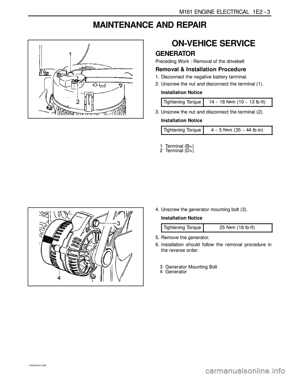
GENERATOR
Preceding Work : Removal of the drivebelt
Removal & Installation Procedure
1. Disconnect the negative battery terminal.
2. Unscrew the nut and disconnect the terminal (1).
Installation Notice
Tightening Torque
14 -- 18 NSm (10 -- 13 lb-ft)
3. Unscrew the nut and disconnect the terminal (2).
Installation Notice
Tightening Torque
4--5NSm (35 -- 44 lb-in)
1 Terminal (B+)
2 Terminal (D+)
4. Unscrew the generator mounting bolt (3).
Installation Notice
Tightening Torque
25 NSm (18 lb-ft)
5. Remove the generator.
6. Installation should follow the removal procedure in
the reverse order.
3 Generator Mounting Bolt
4 Generator
Page 415 of 2053

1E 2 -- 4 M161 ENGINE ELECTRICAL
D AEW OO M Y_2000
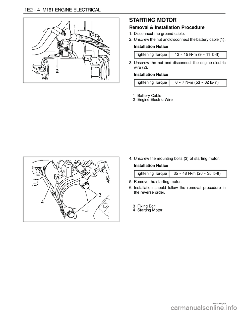
STARTING MOTOR
Removal & Installation Procedure
1. Disconnect the ground cable.
2. Unscrew the nut and disconnect the battery cable (1).
Installation Notice
Tightening Torque
12 -- 15 NSm (9 -- 11 lb-ft)
3. Unscrew the nut and disconnect the engine electric
wire (2).
Installation Notice
Tightening Torque
6--7NSm (53 -- 62 lb-in)
1 Battery Cable
2 Engine Electric Wire
4. Unscrew the mounting bolts (3) of starting motor.
Installation Notice
Tightening Torque
35 -- 48 NSm (26 -- 35 lb-ft)
5. Remove the starting motor.
6. Installation should follow the removal procedure in
the reverse order.
3 Fixing Bolt
4StartingMotor
Page 418 of 2053

M161 ENGINE ELECTRICAL 1E 2 -- 7
D AEW OO M Y_2000
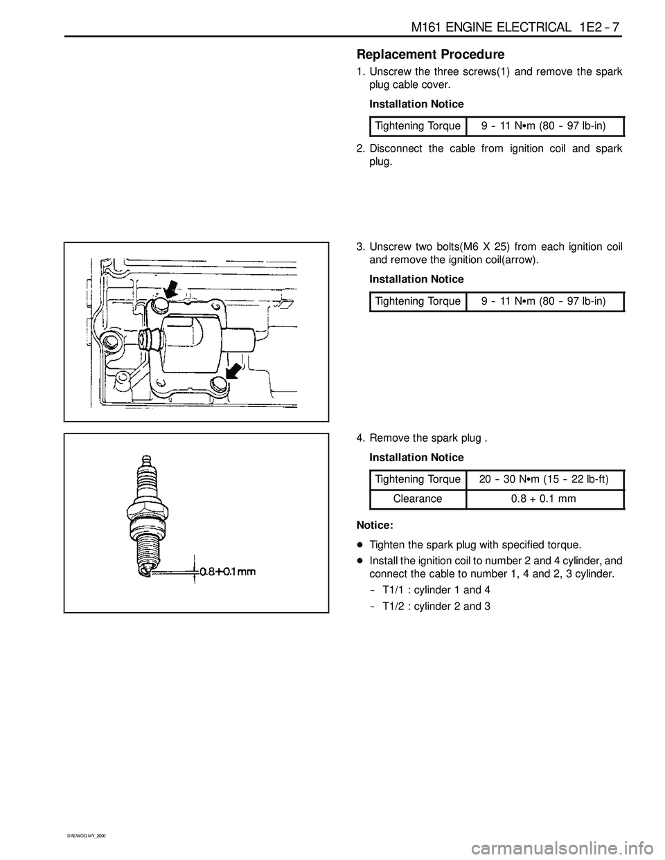
Replacement Procedure
1. Unscrew the three screws(1) and remove the spark
plug cable cover.
Installation Notice
Tightening Torque
9--11NSm (80 -- 97 lb-in)
2. Disconnect the cable from ignition coil and spark
plug.
3. Unscrew two bolts(M6 X 25) from each ignition coil
and remove the ignition coil(arrow).
Installation Notice
Tightening Torque
9--11NSm (80 -- 97 lb-in)
4. Remove the spark plug .
Installation Notice
Tightening Torque
20 -- 30 NSm (15 -- 22 lb-ft)
Clearance0.8+0.1mm
Notice:
DTighten the spark plug with specified torque.
DInstall the ignition coil to number 2 and 4 cylinder, and
connect the cable to number 1, 4 and 2, 3 cylinder.
-- T1/1 : cylinder 1 and 4
-- T1/2 : cylinder 2 and 3
Page 420 of 2053

M161 ENGINE ELECTRICAL 1E 2 -- 9
D AEW OO M Y_2000
Removal & Installation Procedure
1. Disconnect the battery negative cable.
2. Unscrew the 3 screws and remove the ignition cable
duct cover.
Installation Notice
Tightening Torque
9--11NSm (80 -- 97 lb-in)
3. Seperate the cable from the ignition cable and the
spark plug.
4. Remove the 2 bolts from each ignition cable and re-
move the ignition cables.
Installation Notice
Tightening Torque
9--11NSm (80 -- 97 lb-in)
Install the ignition cable to the cylinder 2 and 4 and
connect the cable from 1 to 4, and from 2 to 3.
-- T1/1 : Cylinder 1 and 4
-- T1/2 : Cylinder 2 and 3
5. Installation should follow the removal procedure in
the reverse order.
Ignition Cable and Cable Lay- out
1. Firing Order : 1 -- 3 -- 4 -- 2
2. T1/1 : Connect the cylinder 1 + 4
3. T1/2 : Connect the cylinder 2 + 3
Inspection & Maintenance (for E2.3 MSE)
1. Measure the primary resistance between the cable
terminals 1 and 15 after removing the ignition cable
wiring connector (1 and 15) with ignition switch OFF.
Notice:Replace the ignition coil if out of the specified
resistance.
Specified Value
0.9 -- 1.6Ω
2. Measure the primary voltage(T1/1) between the ECU
terminals No.72 and No.69 during the engine crank-
ing (starter motor activated).
Specified Value
200 -- 350 v
Page 425 of 2053

M161 ENGINE CONTROLS 1F2 -- 3
D AEW OO M Y_2000
SPECIFICATIONS
ENGINE DATA DISPLAY TABLE
ParameterUnitVa l u e
Engine Coolant Temp.°Cgreater than 95_Cafterwarmup
Intake Air Temp.°C-- 40 ~ 130_C (varies with ambient
temp. or engine mode)
Engine RPMrpm700±50 (P/N), 600±50 (D)
Regular RPMrpm700±50 (P/N), 600±50 (D)
Engine Load%18 ~ 25 %
Mass Air Flow MeterKg/h16 ~ 25 Kg/h
Throttle Position Angle_TA0_TA(upto100_TA at the wide
open throttle)
Spark Advance_CA8_CA (6 ~ 9_CA)
Indicated Engine TorqueNmVaries with engine condition
Injection Timems3~5ms
Battery VoltageV13.5 ~ 14.1 v (engine running)
Front Axle SpeedKm/h0~265Km/h
Rear Axle SpeedKm/h0~265Km/h
Accel. Pedal Position 1V0.4~4.8V
Accel. Pedal Position 2V0.2~2.4V
Throttle Position 1V0.3~4.6V
Throttle Position 2V0.3~4.6V
Fuel Integrator0.8 ~ 1.2
Oxygen Sensormv100 ~ 900 mv
A/C S/W Condition1=ON/0=OFF--
Full Load State1=ON/0=OFF--
Shift Gear State (A/T)1=ON/0=OFF--
A/CControlState1=ON/0=OFF--
Clutch Switch (M/T)1=ON/0=OFF--
Cam Actuator State1=ON/0=OFF--
Knocking Control1=ON/0=OFF--
Protect Mission1=ON/0=OFF--
Purge Control Valve1=ON/0=OFF--
Lambda Function1=ON/0=OFF--
Catalyst Heating1=ON/0=OFF--
Overrun Fuel Cut1=ON/0=OFF--
Full Fuel Cut1=ON/0=OFF--
Brake Switch1=ON/0=OFF--
Cruise Control Status1=ON/0=OFF--
* Condition : Warmed up, idle, P/N or neutral