torque SSANGYONG KORANDO 1997 Service Repair Manual
[x] Cancel search | Manufacturer: SSANGYONG, Model Year: 1997, Model line: KORANDO, Model: SSANGYONG KORANDO 1997Pages: 2053, PDF Size: 88.33 MB
Page 521 of 2053

M161 ENGINE CONTROLS 1F2 -- 103
D AEW OO M Y_2000
KAA1F410
PEDAL POSITION SENSOR
Removal and installation Procedure
1. Disconnect the negative battery cable.
2. Disconnect the pedal position sensor connector.
3. Unscrew the bolts and nut.
Installation Notice
Tightening Torque
6NSm (53 lb-in)
4. Remove the pedal and sensor assembly.
5. Installation should follow the removal procedure in
the reverse order.
YAA1F820
OXYGEN SENSOR
Removal and Installation Procedure
1. Disconnect the negative battery cable.
Notice:The oxygen sensor uses a permanently at-
tached pigtail and connector. This pigtail should not be
removed from the oxygen sensor. Damage or removal
of the pigtail or the connector could affect proper opera-
tion of the oxygen sensor. Do not drop the oxygen sen-
sor.
2. Disconnect the electrical connector.
3. Carefully remove the oxygen sensor from the exhaust
pipe.
Installation Notice
Tightening Torque
55 NSm (41 Ib-ft)
Important:A special anti-seize compound is used on
the oxygen sensor threads. This compound consists of
a liquid graphite and glass beads. The graphitewill burn
away, but the glass beadswill remain, making the sen-
sor easier to remove. New or serviced sensors will al-
ready have the compound applied to the threads. If a
sensor is removed from any engine and is to be rein-
stalled, the threads must have an anti-seize compound
applied before reinstallation.
4. Coat the threads of the oxygen sensor with an anti-
seize compound, if needed.
5. Installation should follow the removal procedure in
the reverse order.
Page 522 of 2053

1F2 -- 104 M161 ENGINE CONTROLS
D AEW OO M Y_2000
KAB1F400
PURGE CONTROL VALVE
Removal and Installation Procedure
1. Disconnect the negative battery cable.
2. Disconnect the purge control valve connector.
3. Disconnect the throttle body-to-purge control valve
hose from the purge control valve.
4. Disconnect the canister-to-purge control valve hose
from the purge control valve.
5. Remove the purge control valve.
6. Installation should follow the removal provedure in
the reverse order.
KAB1F410
CANISTER
Removal and Installation Procedure
Caution: Canister and vacuum hoses contain fuel
vapors. Do not smoke in the area or permit an open
flame.
1. Disconnect the fuel tank-to-canister hose form the
canister.
2. Disconnect the canister-to-purge control valve hose
form the canister.
KAB1F400
3. Remove the canister mounting bolts.
Installation Notice
Tightening Torque
6NSm (53 lb-in)
4. Remove the canister.
5. Installation should follow the removal procedure in
the reverse order.
YAA1F810
CAMSHAFT POSITION SENSOR
Removal and Installation Procedure
1. Disconnect the negative battery cable.
2. Disconnect the electrical connector from the cam-
shaft position sensor.
3. Remove the camshaft position sensor retaining bolt.
Installation Notice
Tightening Torque
10 NSm (89 Ib-in)
Page 523 of 2053
M161 ENGINE CONTROLS 1F2 -- 105
D AEW OO M Y_2000
4. Check the O-ring for damage and replace it if neces-
sary.
5. Installation should follow the removal procedure in
the reverse order.
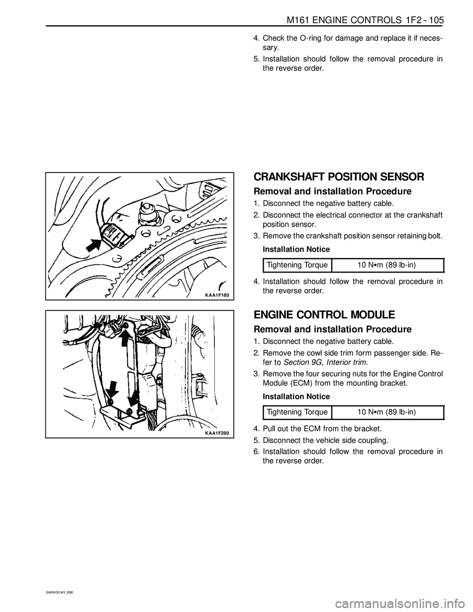
KAA1F160
CRANKSHAFT POSITION SENSOR
Removal and installation Procedure
1. Disconnect the negative battery cable.
2. Disconnect the electrical connector at the crankshaft
position sensor.
3. Remove the crankshaft position sensor retaining bolt.
Installation Notice
Tightening Torque
10 NSm (89 lb-in)
4. Installation should follow the removal procedure in
the reverse order.
KAA1F200
ENGINE CONTROL MODULE
Removal and installation Procedure
1. Disconnect the negative battery cable.
2. Remove the cowl side trim form passenger side. Re-
fer toSection 9G, Interior trim.
3. Remove the four securing nuts for the Engine Control
Module (ECM) from the mounting bracket.
Installation Notice
Tightening Torque
10 NSm (89 lb-in)
4. Pull out the ECM from the bracket.
5. Disconnect the vehicle side coupling.
6. Installation should follow the removal procedure in
the reverse order.
Page 527 of 2053

1G2 -- 4 M161 ENGINE INTAKE & EXHAUST
D AEW OO M Y_2000
Removal and Installation Procedure
1. Disconnect the HFM sensor and the air cleaner by
prying up the clamp.
2. Remove the air cleaner mounting bolt.
Installation Notice
Tightening Torque
22.5 -- 27.5 NSm
(16.6 -- 20.3 lb-ft)
3. Remove air intake shield upper cover, and then re-
move the air cleaner from rubber bearing on bracket.
Notice:For installation, exactly seat the air cleaner into
the rubber bearing.
Page 532 of 2053
M161 ENGINE INTAKE & EXHAUST 1G2 -- 9
D AEW OO M Y_2000
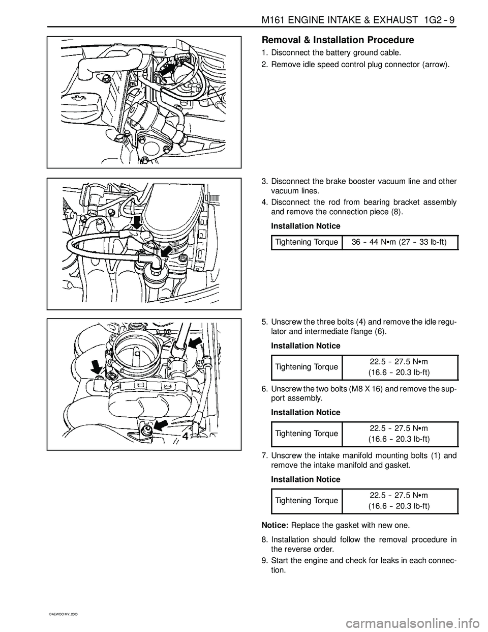
Removal & Installation Procedure
1. Disconnect the battery ground cable.
2. Remove idle speed control plug connector (arrow).
3. Disconnect the brake booster vacuum line and other
vacuum lines.
4. Disconnect the rod from bearing bracket assembly
and remove the connection piece (8).
Installation Notice
Tightening Torque
36 -- 44 NSm (27 -- 33 lb-ft)
5. Unscrew the three bolts (4) and remove the idle regu-
lator and intermediate flange (6).
Installation Notice
Tightening Torque
22.5 -- 27.5 NSm
(16.6 -- 20.3 lb-ft)
6. Unscrew the two bolts (M8 X 16) and remove the sup-
port assembly.
Installation Notice
Tightening Torque
22.5 -- 27.5 NSm
(16.6 -- 20.3 lb-ft)
7. Unscrew the intake manifold mounting bolts (1) and
remove the intake manifold and gasket.
Installation Notice
Tightening Torque
22.5 -- 27.5 NSm
(16.6 -- 20.3 lb-ft)
Notice:Replace the gasket with new one.
8. Installation should follow the removal procedure in
the reverse order.
9. Start the engine and check for leaks in each connec-
tion.
Page 534 of 2053
M161 ENGINE INTAKE & EXHAUST 1G2 -- 11
D AEW OO M Y_2000
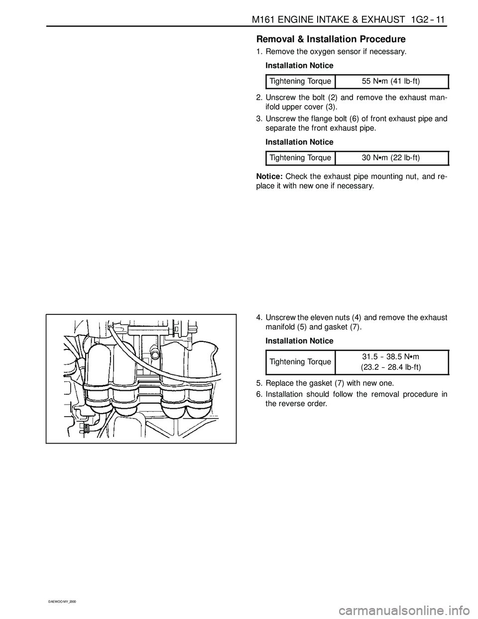
Removal & Installation Procedure
1. Remove the oxygen sensor if necessary.
Installation Notice
Tightening Torque
55 NSm (41 lb-ft)
2. Unscrew the bolt (2) and remove the exhaust man-
ifold upper cover (3).
3. Unscrew the flange bolt (6) of front exhaust pipe and
separate the front exhaust pipe.
Installation Notice
Tightening Torque
30 NSm (22 lb-ft)
Notice:Check the exhaust pipe mounting nut, and re-
place it with new one if necessary.
4. Unscrew the eleven nuts (4) and remove the exhaust
manifold (5) and gasket (7).
Installation Notice
Tightening Torque
31.5 -- 38.5 NSm
(23.2 -- 28.4 lb-ft)
5. Replace the gasket (7) with new one.
6. Installation should follow the removal procedure in
the reverse order.
Page 536 of 2053

D AEW OO M Y_2000
SECTION 1
ENGINE
SECTION 1A3 (OM600 ENGINE)
GENERAL ENGINE INFORMATION
TABLE OF CONTENTS
Specifications 1A3 -- 1............................
Engine Specifications 1A3-- 1.....................
Sectional View 1A3 -- 3............................
OM662LA Engine 1A3-- 3........................
OM661LA Engine 1A3-- 5........................
Performance Curve 1A3-- 7........................
OM662LA Engine 1A3-- 7........................
OM661LA Engine 1A3-- 8........................
Special Tools 1A3 -- 9.............................Special Tools Table 1A3-- 9.......................
Diagnosis 1A3 -- 10................................
Oil Leak Diagnosis 1A3-- 10.......................
Compression Pressure Test 1A3-- 11..............
Cylinder Pressure Leakage Test 1A3-- 13...........
General Information 1A3 -- 15......................
Cleanliness and Care 1A3 -- 15....................
On-- Engine Service 1A3-- 15......................
SPECIFICATIONS
ENGINE SPECIFICATIONS
ApplicationOM662LAOM661LA
Engine TypeFour -- Stroke DieselFour -- Stroke Diesel
Displacement (CC)28742299
Cylinder (Bore x Stroke)(mm)89 x 92.489 x 92.4
Fuel Injection / Ignition SystemPES 5 M55 C320 RS 168PES 5 M55 C320 RS 167
Compression Ratio22 :122 :1
Number of Cylinders54
Camshaft Valve ArrangementSOHCSOHC
Camshaft Drive TypeChain -- DriveChain-- Drive
Max. Output (ps/rpm)120 / 4000101 / 4000
Max. Torque (kgSm/rpm)25.5 / 400021.5 / 2400
Firing Order1--2--4--5--31--3--4--2
Injection TimingBTDC 18_±10_BTDC 18_±10_
Valve Timing
(t2lift)
IntakeOpen/CloseAT DC 11 . 3 3_/ ABDC 17_AT DC 11 . 3 3_/ ABDC 17_g
(at 2mm lift)ExhaustOpen/CloseBBDC 28_/ BTDC 15.25_BBDC 28_/ BTDC 15.25_
Valve Clearance AdjustmentAutomatic ControlAutomatic Control
Page 544 of 2053

GENERAL ENGINE INFORMATION 1A3 -- 9
D AEW OO M Y_2000
SPECIAL TOOLS
SPECIAL TOOLS TABLE
000 589 10 99 01
Torque Wrench
001 589 76 21 00
Compression Pressure
Tester
601 589 65 09 00
Socket
001 589 73 21 00
Hand Vacuum Pump
Page 562 of 2053
OM600 ENGINE MECHANICAL 1B3 -- 13
D AEW OO M Y_2000
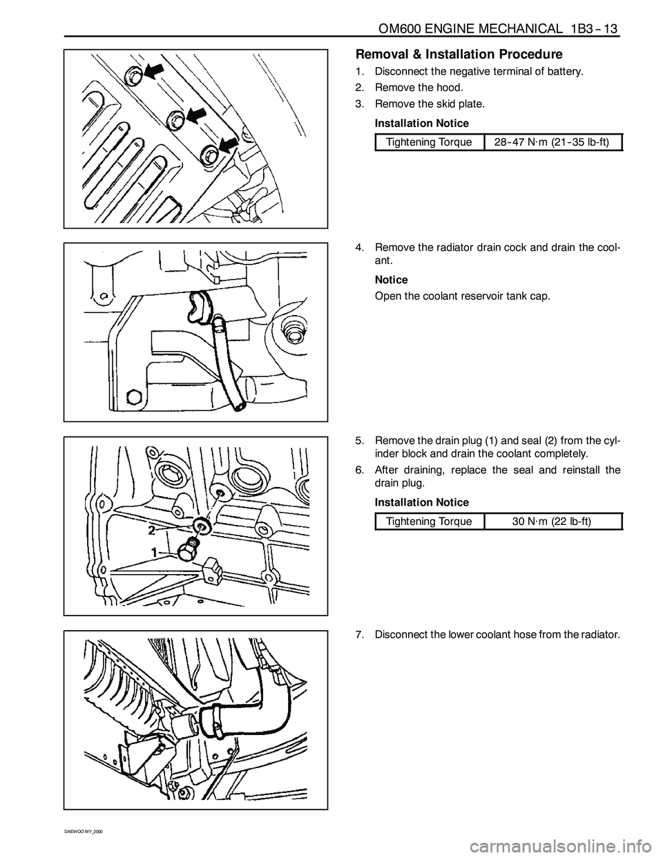
Removal & Installation Procedure
1. Disconnect the negative terminal of battery.
2. Remove the hood.
3. Remove the skid plate.
Installation Notice
Tightening Torque28-- 47 N∙m (21-- 35 lb-ft)
4. Remove the radiator drain cock and drain the cool-
ant.
Notice
Open the coolant reservoir tank cap.
5. Remove the drain plug (1) and seal (2) from the cyl-
inder block and drain the coolant completely.
6. After draining, replace the seal and reinstall the
drain plug.
Installation Notice
Tightening Torque30 N∙m (22 lb-ft)
7. Disconnect the lower coolant hose from the radiator.
Page 563 of 2053
1B3 -- 14 OM600 ENGINE MECHANICAL
D AEW OO M Y_2000
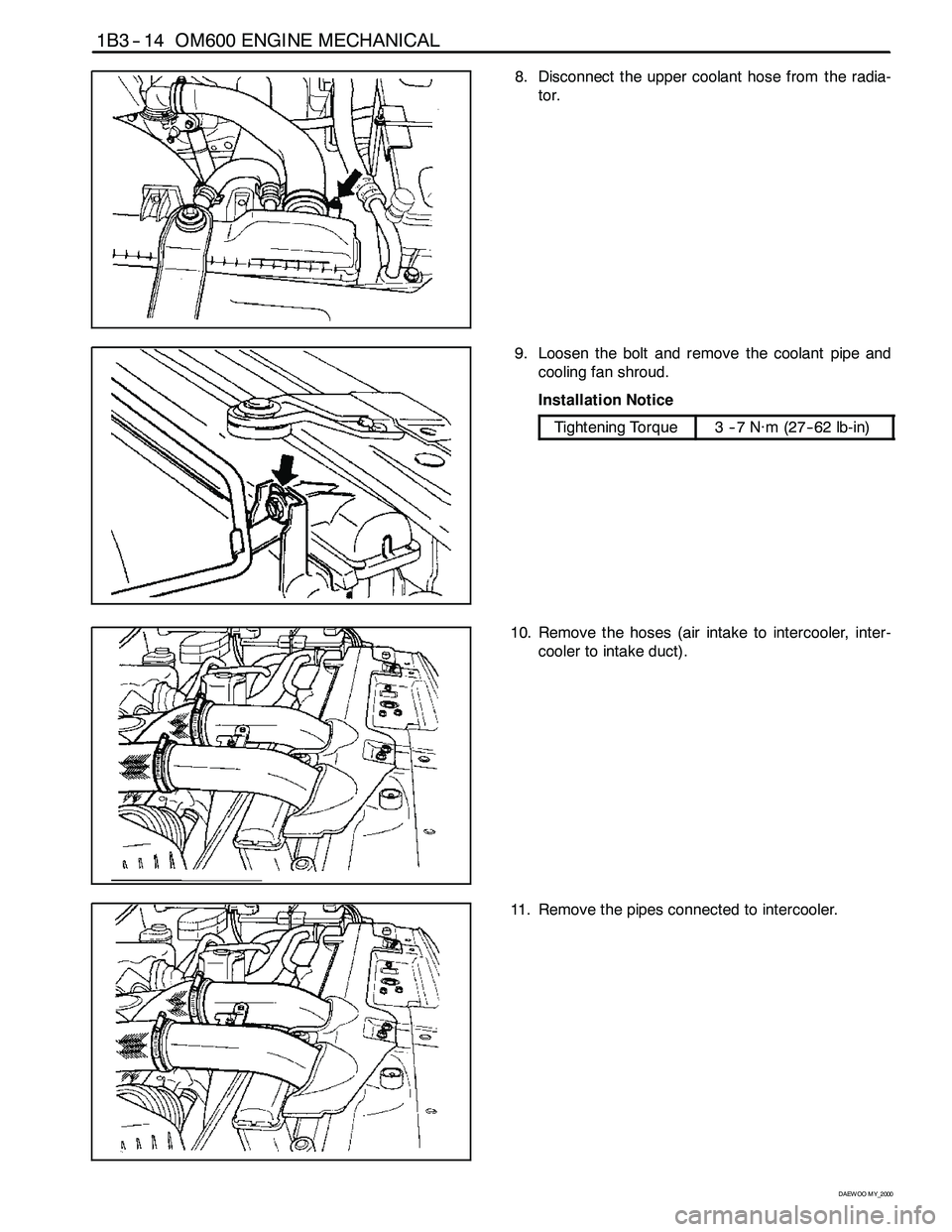
8. Disconnect the upper coolant hose from the radia-
tor.
9. Loosen the bolt and remove the coolant pipe and
cooling fan shroud.
Installation Notice
Tightening Torque3--7N∙m (27-- 62 lb-in)
10. Remove the hoses (air intake to intercooler, inter-
cooler to intake duct).
11. Remove the pipes connected to intercooler.