SSANGYONG KORANDO 1997 Service Repair Manual
Manufacturer: SSANGYONG, Model Year: 1997, Model line: KORANDO, Model: SSANGYONG KORANDO 1997Pages: 2053, PDF Size: 88.33 MB
Page 1291 of 2053
5A-196 AUTOMATIC TRANSMISSION
SSANGYONG MY2002
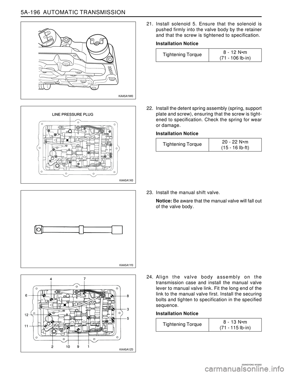
21. Install solenoid 5. Ensure that the solenoid is
pushed firmly into the valve body by the retainer
and that the screw is tightened to specification.
Installation Notice
22. Install the detent spring assembly (spring, support
plate and screw), ensuring that the screw is tight-
ened to specification. Check the spring for wear
or damage.
Installation Notice
23. Install the manual shift valve.
Notice: Be aware that the manual valve will fall out
of the valve body.
24. Align the valve body assembly on the
transmission case and install the manual valve
lever to manual valve link. Fit the long end of the
link to the manual valve first. Install the securing
bolts and tighten to specification in the specified
sequence.
Installation Notice
KAA5A1Y0 KAA5A1X0
KAA5A1Z0 KAA5A1W0
Tightening Torque8 - 12 Nm
(71 - 106 lb-in)
Tightening Torque20 - 22 Nm
(15 - 16 lb-ft)
Tightening Torque8 - 13 Nm
(71 - 115 lb-in)
Page 1292 of 2053
AUTOMATIC TRANSMISSION 5A-197
SSANGYONG MY2002
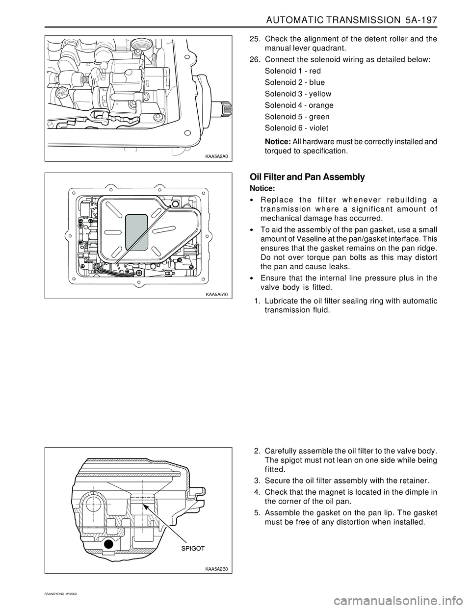
2. Carefully assemble the oil filter to the valve body.
The spigot must not lean on one side while being
fitted.
3. Secure the oil filter assembly with the retainer.
4. Check that the magnet is located in the dimple in
the corner of the oil pan.
5. Assemble the gasket on the pan lip. The gasket
must be free of any distortion when installed. 25. Check the alignment of the detent roller and the
manual lever quadrant.
26. Connect the solenoid wiring as detailed below:
Solenoid 1 - red
Solenoid 2 - bIue
Solenoid 3 - yellow
Solenoid 4 - orange
Solenoid 5 - green
Solenoid 6 - violet
Notice: All hardware must be correctly installed and
torqued to specification.
Oil Filter and Pan Assembly
Notice:
Replace the filter whenever rebuilding a
transmission where a significant amount of
mechanical damage has occurred.
To aid the assembly of the pan gasket, use a small
amount of Vaseline at the pan/gasket interface. This
ensures that the gasket remains on the pan ridge.
Do not over torque pan bolts as this may distort
the pan and cause leaks.
Ensure that the internal line pressure plus in the
valve body is fitted.
1. Lubricate the oil filter sealing ring with automatic
transmission fluid.
KAA5A2B0 KAA5A2A0
KAA5A510
Page 1293 of 2053
5A-198 AUTOMATIC TRANSMISSION
SSANGYONG MY2002
Torque Converter and Housing Assembly
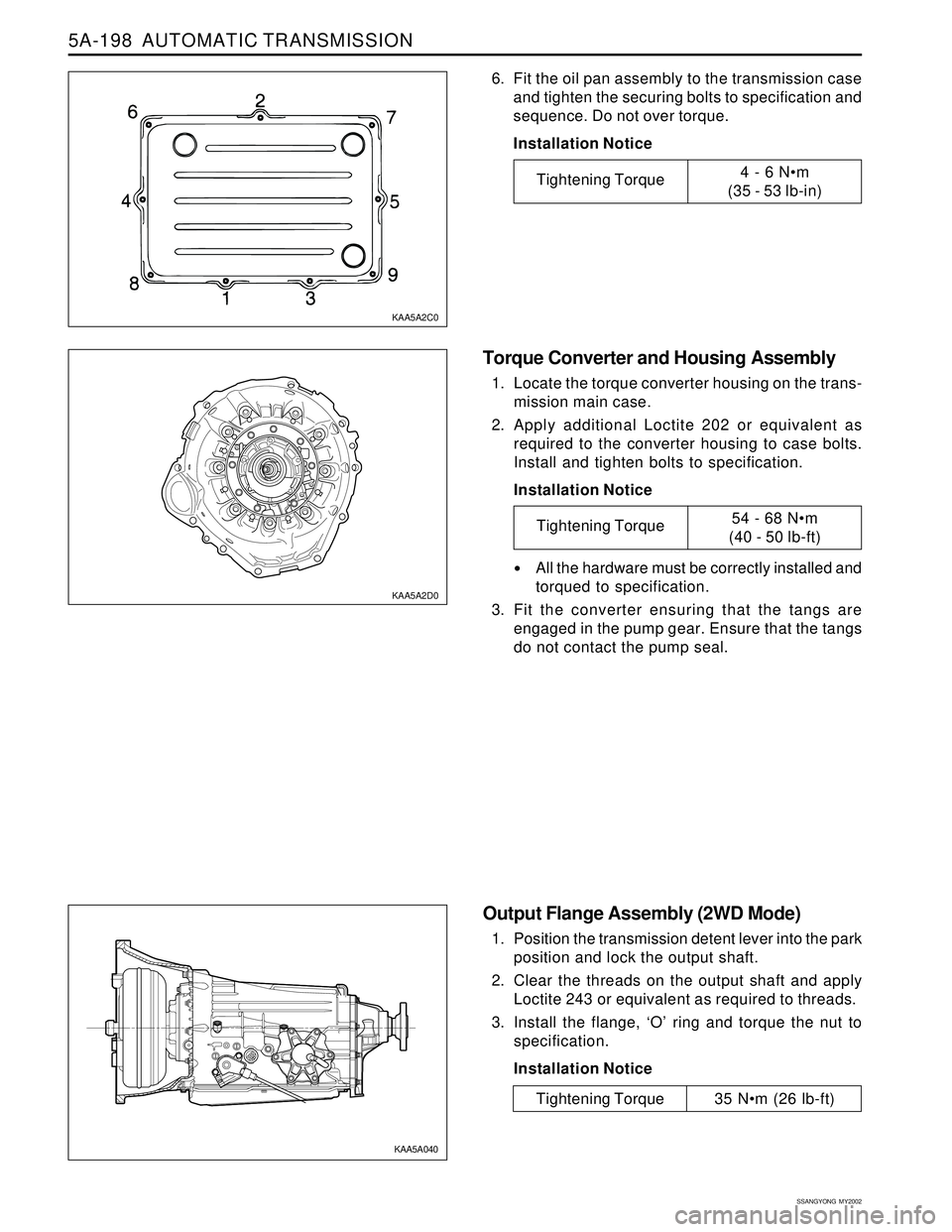
1. Locate the torque converter housing on the trans-
mission main case.
2. Apply additional Loctite 202 or equivalent as
required to the converter housing to case bolts.
Install and tighten bolts to specification.
Installation Notice
All the hardware must be correctly installed and
torqued to specification.
3. Fit the converter ensuring that the tangs are
engaged in the pump gear. Ensure that the tangs
do not contact the pump seal.
Output Flange Assembly (2WD Mode)
1. Position the transmission detent lever into the park
position and lock the output shaft.
2. Clear the threads on the output shaft and apply
Loctite 243 or equivalent as required to threads.
3. Install the flange, ‘O’ ring and torque the nut to
specification.
Installation Notice
6. Fit the oil pan assembly to the transmission case
and tighten the securing bolts to specification and
sequence. Do not over torque.
Installation Notice
KAA5A2C0
KAA5A2D0
KAA5A040
Tightening Torque4 - 6 Nm
(35 - 53 lb-in)
Tightening Torque54 - 68 Nm
(40 - 50 lb-ft)
Tightening Torque 35 Nm (26 lb-ft)
Page 1294 of 2053
AUTOMATIC TRANSMISSION 5A-199
SSANGYONG MY2002
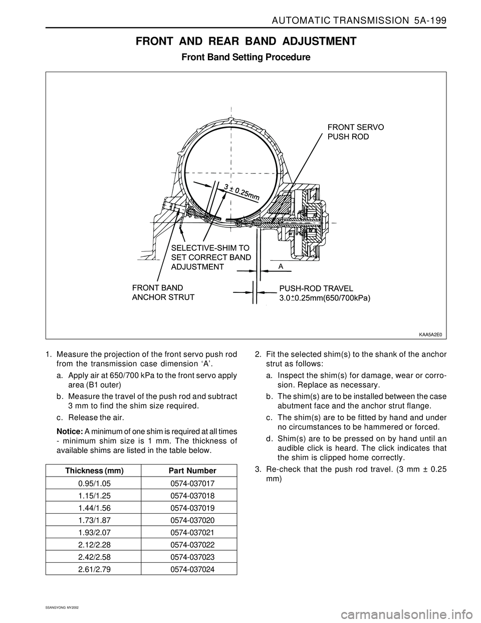
1. Measure the projection of the front servo push rod
from the transmission case dimension ‘A’.
a. Apply air at 650/700 kPa to the front servo apply
area (B1 outer)
b. Measure the travel of the push rod and subtract
3 mm to find the shim size required.
c. Release the air.
Notice: A minimum of one shim is required at all times
- minimum shim size is 1 mm. The thickness of
available shims are listed in the table below.
FRONT AND REAR BAND ADJUSTMENT
Front Band Setting Procedure
2. Fit the selected shim(s) to the shank of the anchor
strut as follows:
a. Inspect the shim(s) for damage, wear or corro-
sion. Replace as necessary.
b . The shim(s) are to be installed between the case
abutment face and the anchor strut flange.
c. The shim(s) are to be fitted by hand and under
no circumstances to be hammered or forced.
d. Shim(s) are to be pressed on by hand until an
audible click is heard. The click indicates that
the shim is clipped home correctly.
3. Re-check that the push rod travel. (3 mm ± 0.25
mm)
KAA5A2E0
Thickness (mm)Part Number
0.95/1.050574-037017
1.15/1.250574-037018
1.44/1.560574-037019
1.73/1.870574-037020
1.93/2.070574-037021
2.12/2.280574-037022
2.42/2.580574-037023
2.61/2.790574-037024
Page 1295 of 2053
5A-200 AUTOMATIC TRANSMISSION
SSANGYONG MY2002
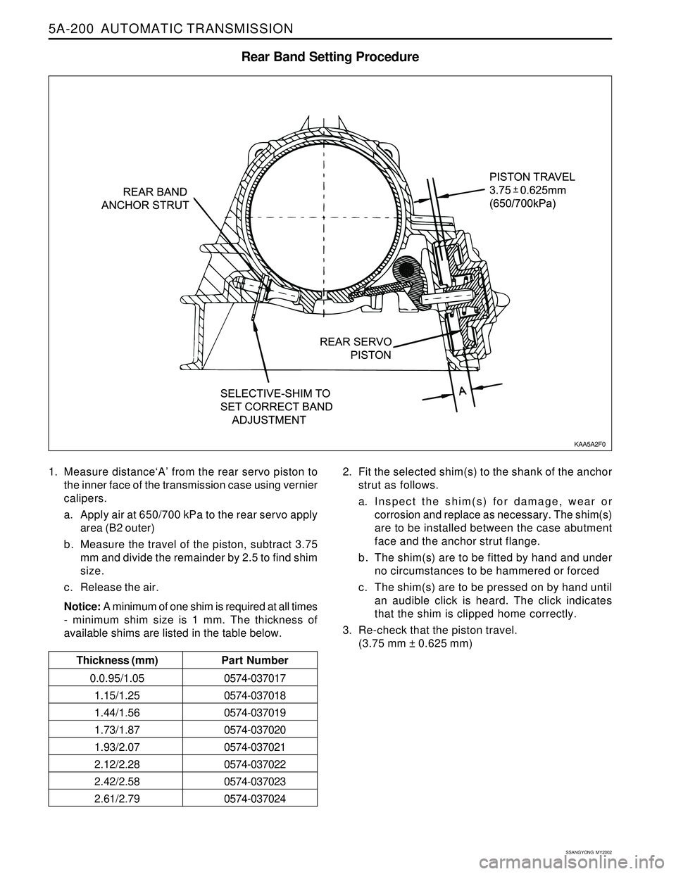
1. Measure distance‘A’ from the rear servo piston to
the inner face of the transmission case using vernier
calipers.
a. Apply air at 650/700 kPa to the rear servo apply
area (B2 outer)
b. Measure the travel of the piston, subtract 3.75
mm and divide the remainder by 2.5 to find shim
size.
c. Release the air.
Notice: A minimum of one shim is required at all times
- minimum shim size is 1 mm. The thickness of
available shims are listed in the table below.
Rear Band Setting Procedure
2. Fit the selected shim(s) to the shank of the anchor
strut as follows.
a. Inspect the shim(s) for damage, wear or
corrosion and replace as necessary. The shim(s)
are to be installed between the case abutment
face and the anchor strut flange.
b. The shim(s) are to be fitted by hand and under
no circumstances to be hammered or forced
c. The shim(s) are to be pressed on by hand until
an audible click is heard. The click indicates
that the shim is clipped home correctly.
3. Re-check that the piston travel.
(3.75 mm ± 0.625 mm)
KAA5A2F0
Thickness (mm)Part Number
0.0.95/1.050574-037017
1.15/1.25 0574-037018
1.44/1.56 0574-037019
1.73/1.87 0574-037020
1.93/2.07 0574-037021
2.12/2.28 0574-037022
2.42/2.58 0574-037023
2.61/2.79 0574-037024
Page 1296 of 2053
AUTOMATIC TRANSMISSION 5A-201
SSANGYONG MY2002
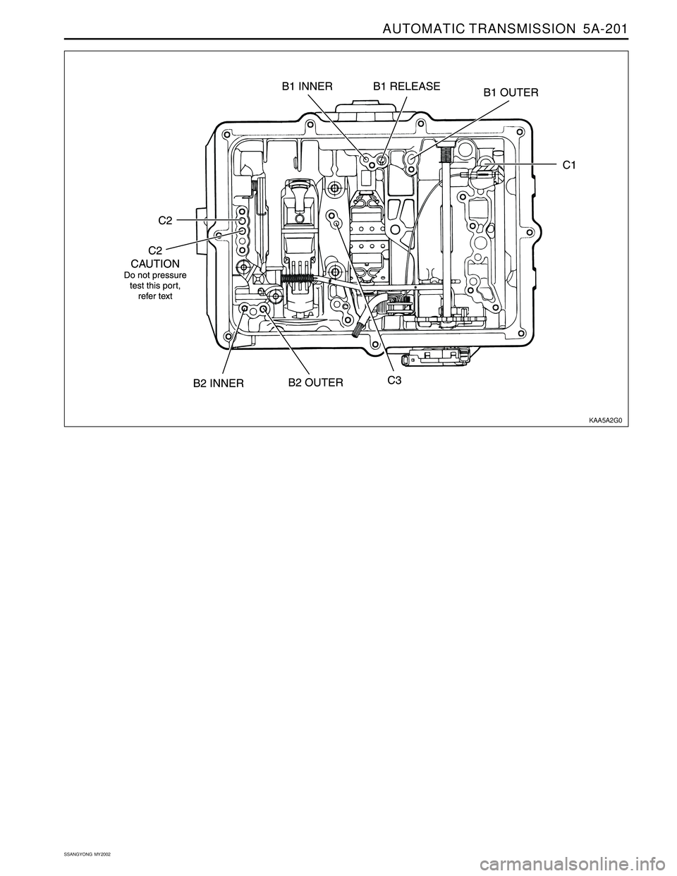
KAA5A2G0
Page 1297 of 2053
5A-202 AUTOMATIC TRANSMISSION
SSANGYONG MY2002
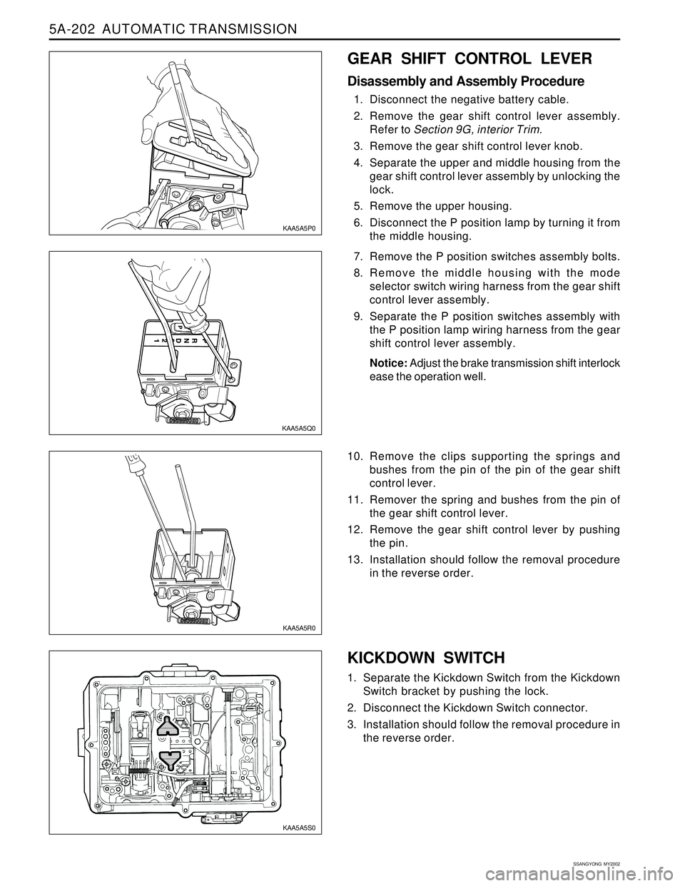
KICKDOWN SWITCH
1. Separate the Kickdown Switch from the Kickdown
Switch bracket by pushing the lock.
2. Disconnect the Kickdown Switch connector.
3. Installation should follow the removal procedure in
the reverse order.
KAA5A5S0
GEAR SHIFT CONTROL LEVER
Disassembly and Assembly Procedure
1. Disconnect the negative battery cable.
2. Remove the gear shift control lever assembly.
Refer to Section 9G, interior Trim.
3. Remove the gear shift control lever knob.
4. Separate the upper and middle housing from the
gear shift control lever assembly by unlocking the
lock.
5. Remove the upper housing.
6. Disconnect the P position lamp by turning it from
the middle housing.
7. Remove the P position switches assembly bolts.
8. Remove the middle housing with the mode
selector switch wiring harness from the gear shift
control lever assembly.
9. Separate the P position switches assembly with
the P position lamp wiring harness from the gear
shift control lever assembly.
Notice: Adjust the brake transmission shift interlock
ease the operation well.
10. Remove the clips supporting the springs and
bushes from the pin of the pin of the gear shift
control lever.
11. Remover the spring and bushes from the pin of
the gear shift control lever.
12. Remove the gear shift control lever by pushing
the pin.
13. Installation should follow the removal procedure
in the reverse order.
KAA5A5P0
KAA5A5Q0
KAA5A5R0
Page 1298 of 2053
AUTOMATIC TRANSMISSION 5A-203
SSANGYONG MY2002
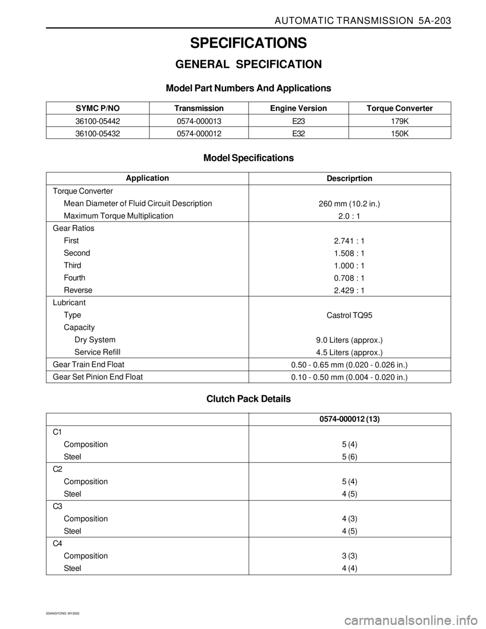
SPECIFICATIONS
GENERAL SPECIFICATION
Model Specifications
Clutch Pack Details Model Part Numbers And Applications
Descriprtion
260 mm (10.2 in.)
2.0 : 1
2.741 : 1
1.508 : 1
1.000 : 1
0.708 : 1
2.429 : 1
Castrol TQ95
9.0 Liters (approx.)
4.5 Liters (approx.)
0.50 - 0.65 mm (0.020 - 0.026 in.)
0.10 - 0.50 mm (0.004 - 0.020 in.)Application
Torque Converter
Mean Diameter of Fluid Circuit Description
Maximum Torque Multiplication
Gear Ratios
First
Second
Third
Fourth
Reverse
Lubricant
Type
Capacity
Dry System
Service Refill
Gear Train End Float
Gear Set Pinion End Float
Transmission
0574-000013
0574-000012Torque Converter
179K
150K Engine Version
E23
E32 SYMC P/NO
36100-05442
36100-05432
C1
Composition
Steel
C2
Composition
Steel
C3
Composition
Steel
C4
Composition
Steel
0574-000012 (13)
5 (4)
5 (6)
5 (4)
4 (5)
4 (3)
4 (5)
3 (3)
4 (4)
Page 1299 of 2053
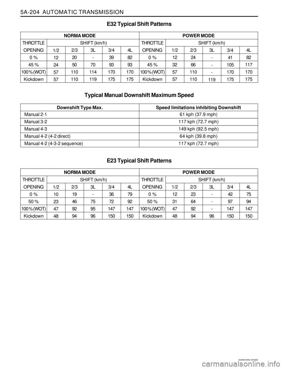
5A-204 AUTOMATIC TRANSMISSION
SSANGYONG MY2002
Speed limitations inhibiting Downshift Downshift Type Max.
1/2
12
32
57
573L
-
-
-
119 2/3
24
66
110
1104L
82
117
170
175 1/2
12
24
57
573/4
39
93
170
175 3L
-
70
114
119 2/3
20
50
110
1104L
82
93
170
175 NORMA MODE
E32 Typical Shift Patterns
THROTTLE
OPENING
0 %
45 %
100 % (WOT)
Kickdown
POWER MODE
SHIFT (km/h)THROTTLE
OPENING
0 %
45 %
100 % (WOT)
KickdownSHIFT (km/h)
Typical Manual Downshift Maximum Speed
Manual 2-1
Manual 3-2
Manual 4-3
Manual 4-2 (4-2 direct)
Manual 4-2 (4-3-2 sequence)61 kph (37.9 mph)
117 kph (72.7 mph)
149 kph (92.5 mph)
64 kph (39.8 mph)
117 kph (72.7 mph)
1/2
12
31
47
483/4
42
97
147
150 3L
-
-
-
96 2/3
23
64
92
944L
75
94
147
150 1/2
10
23
47
483/4
36
72
147
150 3L
-
75
95
96 2/3
19
46
92
944L
79
92
147
150 NORMA MODE
E23 Typical Shift Patterns
THROTTLE
OPENING
0 %
50 %
100 % (WOT)
Kickdown
POWER MODE
SHIFT (km/h)THROTTLE
OPENING
0 %
50 %
100 % (WOT)
KickdownSHIFT (km/h)3/4
41
105
170
175
Page 1300 of 2053
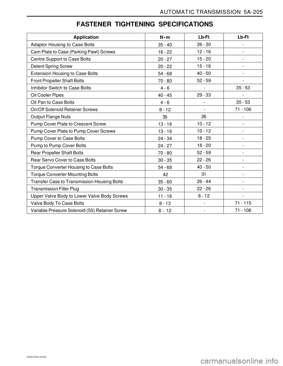
AUTOMATIC TRANSMISSION 5A-205
SSANGYONG MY2002
FASTENER TIGHTENING SPECIFICATIONS
N•m
35 - 40
16 - 22
20 - 27
20 - 22
54 - 68
70 - 80
4 - 6
40 - 45
4 - 6
8 - 12
35
13 - 16
13 - 16
24 - 34
24 - 27
70 - 80
30 - 35
54 - 68
42
35 - 60
30 - 35
11 - 16
8 - 13
8 - 12Lb-Ft
26 - 30
12 - 16
15 - 20
15 - 16
40 - 50
52 - 59
-
29 - 33
-
-
26
10 - 12
10 - 12
18 - 25
18 - 20
52 - 59
22 - 26
40 - 50
31
26 - 44
22 - 26
8 - 12
-
- Application
Adaptor Housing to Case Bolts
Cam Plate to Case (Parking Pawl) Screws
Centre Support to Case Bolts
Detent Spring Screw
Extension Housing to Case Bolts
Front Propeller Shaft Bolts
Inhibitor Switch to Case Bolts
Oil Cooler Pipes
Oil Pan to Case Bolts
On/Off Solenoid Retainer Screws
Output Flange Nuts
Pump Cover Plate to Crescent Screw
Pump Cover Plate to Pump Cover Screws
Pump Cover to Case Bolts
Pump to Pump Cover Bolts
Rear Propeller Shaft Bolts
Rear Servo Cover to Case Bolts
Torque Converter Housing to Case Bolts
Torque Converter Mounting Bolts
Transfer Case to Transmission Housing Bolts
Transmission Filler Plug
Upper Valve Body to Lower Valve Body Screws
Valve Body To Case Bolts
Variable Pressure Solenoid (S5) Retainer ScrewLb-Ft
-
-
-
-
-
-
35 - 53
-
35 - 53
71 - 106
-
-
-
-
-
-
-
-
-
-
-
-
71 - 115
71 - 106