SUBARU FORESTER 2004 Service Repair Manual
FORESTER 2004
SUBARU
SUBARU
https://www.carmanualsonline.info/img/17/57426/w960_57426-0.png
SUBARU FORESTER 2004 Service Repair Manual
Trending: park assist, power steering, air pressure switch, start stop button, instrument panel, Steering, height adjustment
Page 1071 of 2870
IG(H4SO)-7
IGNITION
Spark Plug
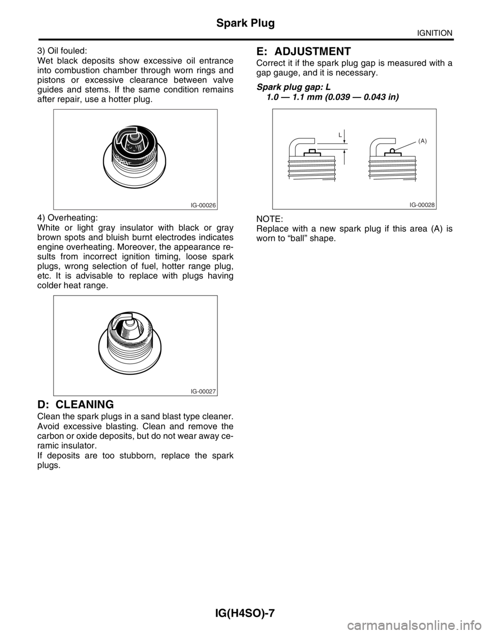
3) Oil fouled:
Wet black deposits show excessive oil entrance
into combustion chamber through worn rings and
pistons or excessive clearance between valve
guides and stems. If the same condition remains
after repair, use a hotter plug.
4) Overheating:
White or light gray insulator with black or gray
brown spots and bluish burnt electrodes indicates
engine overheating. Moreover, the appearance re-
sults from incorrect ignition timing, loose spark
plugs, wrong selection of fuel, hotter range plug,
etc. It is advisable to replace with plugs having
colder heat range.
D: CLEANING
Clean the spark plugs in a sand blast type cleaner.
Avoid excessive blasting. Clean and remove the
carbon or oxide deposits, but do not wear away ce-
ramic insulator.
If deposits are too stubborn, replace the spark
plugs.
E: ADJUSTMENT
Correct it if the spark plug gap is measured with a
gap gauge, and it is necessary.
Spark plug gap: L
1.0 — 1.1 mm (0.039 — 0.043 in)
NOTE:
Replace with a new spark plug if this area (A) is
worn to “ball” shape.
IG-00026
IG-00027
IG-00028
L
(A)
Page 1072 of 2870
IG(H4SO)-8
IGNITION
Ignition Coil & Ignitor Assembly
3. Ignition Coil & Ignitor Assem-
bly
A: REMOVAL
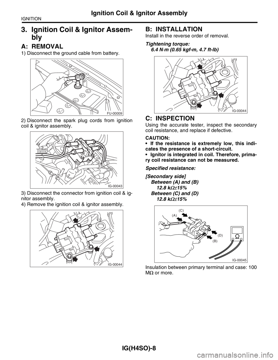
1) Disconnect the ground cable from battery.
2) Disconnect the spark plug cords from ignition
coil & ignitor assembly.
3) Disconnect the connector from ignition coil & ig-
nitor assembly.
4) Remove the ignition coil & ignitor assembly.
B: INSTALLATION
Install in the reverse order of removal.
Tightening torque:
6.4 N
⋅m (0.65 kgf-m, 4.7 ft-lb)
C: INSPECTION
Using the accurate tester, inspect the secondary
coil resistance, and replace if defective.
CAUTION:
If the resistance is extremely low, this indi-
cates the presence of a short-circuit.
Ignitor is integrated in coil. Therefore, prima-
ry coil resistance can not be measured.
Specified resistance:
[Secondary side]
Between (A) and (B)
12.8 k
Ω±15%
Between (C) and (D)
12.8 k
Ω±15%
Insulation between primary terminal and case: 100
MΩ or more.
FU-00009
IG-00043
IG-00044
IG-00044
IG-00045
(C)
(A)
(D)
(B)
Page 1073 of 2870
IG(H4SO)-9
IGNITION
Spark Plug Cord
4. Spark Plug Cord
A: INSPECTION
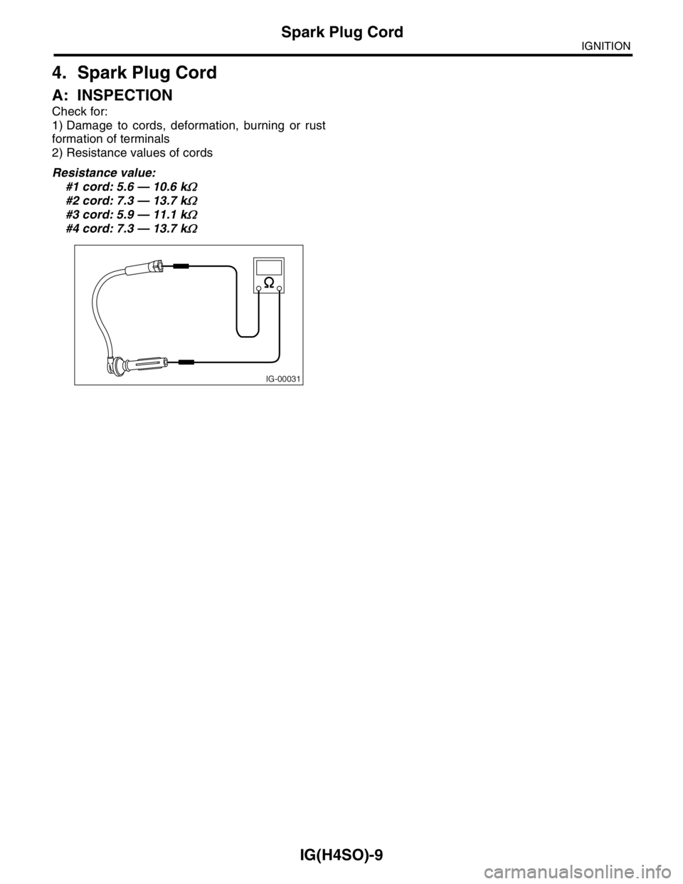
Check for:
1) Damage to cords, deformation, burning or rust
formation of terminals
2) Resistance values of cords
Resistance value:
#1 cord: 5.6 — 10.6 k
Ω
#2 cord: 7.3 — 13.7 kΩ
#3 cord: 5.9 — 11.1 kΩ
#4 cord: 7.3 — 13.7 kΩ
IG-00031
Page 1074 of 2870
IG(H4SO)-10
IGNITION
Spark Plug Cord
Page 1075 of 2870
FUJI HEAVY INDUSTRIES LTD. G8080GE2
2004 FORESTER SERVICE MANUAL QUICK REFERENCE INDEX
ENGINE SECTION 1
This service manual has been prepared
to provide SUBARU service personnel
with the necessary information and data
for the correct maintenance and repair
of SUBARU vehicles.
This manual includes the procedures
for maintenance, disassembling, reas-
sembling, inspection and adjustment of
components and diagnostics for guid-
ance of experienced mechanics.
Please peruse and utilize this manual
fully to ensure complete repair work for
satisfying our customers by keeping
their vehicle in optimum condition.
When replacement of parts during
repair work is needed, be sure to use
SUBARU genuine parts.
All information, illustration and specifi-
cations contained in this manual are
based on the latest product information
available at the time of publication
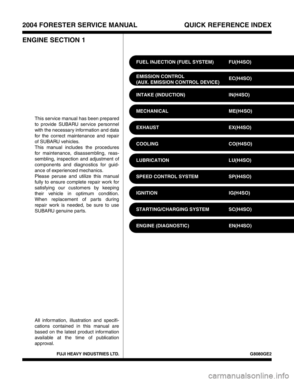
approval.FUEL INJECTION (FUEL SYSTEM) FU(H4SO)
EMISSION CONTROL
(AUX. EMISSION CONTROL DEVICE)EC(H4SO)
INTAKE (INDUCTION) IN(H4SO)
MECHANICAL ME(H4SO)
EXHAUST EX(H4SO)
COOLING CO(H4SO)
LUBRICATION LU(H4SO)
SPEED CONTROL SYSTEM SP(H4SO)
IGNITION IG(H4SO)
STARTING/CHARGING SYSTEM SC(H4SO)
ENGINE (DIAGNOSTIC) EN(H4SO)
Page 1076 of 2870
STARTING/CHARGING SYSTEM
SC(H4SO)
Page
1. General Description ....................................................................................2
2. Starter .........................................................................................................6
3. Generator ..................................................................................................15
4. Battery .......................................................................................................21
Page 1077 of 2870

SC(H4SO)-2
STARTING/CHARGING SYSTEM
General Description
1. General Description
A: SPECIFICATION
Item Designation
StarterType Reduction type
Vehicle type MT model AT model
Model M000T30471 M000T20171
Manufacturer Mitsubishi Electric
Voltage and output 12 V — 1.0 kW 12 V — 1.4 kW
Direction of rotation Counterclockwise (viewed from pinion gear side)
Number of pinion teeth 8 9
No-load charac-
teristicsVo l t a g e 1 1 V
Current 95 A or less 90 A or less
Rotating speed 2,500 rpm or more 2,000 rpm or more
Load character-
isticsVoltage 7.5 V 7.7 V
Current 300 A 400 A
Torque 8.84 N (0.90 kgf, 1.99 lb) or more 16.7 N (1.70 kgf, 3.75 lb) or more
Rotating speed 870 rpm or more 710 rpm or more
Lock character-
isticsVo l t a g e 4 V 3 . 5 V
Current 680 A or less 960 A or less
Torque 17 N (1.73 kgf, 12.5 lb) or more 31 N (3.16 kgf, 22.9 lb) or more
GeneratorTy p eRotating-field three-phase type, Voltage regulator built-in type, with load
response control system
ModelEC, EK model: A002TG0391
Other model: A002TB6991
Manufacturer Mitsubishi Electric
Voltage and output 12 V — 90 A
Polarity on ground side Negative
Rotating direction Clockwise (viewed from pulley side)
Armature connection 3-phase Y-type
Output currentEC, EK model1,500 rpm — 40 A or more
2,500 rpm — 74 A or more
5,000 rpm — 84 A or more
Other model1,500 rpm — 36 A or more
2,500 rpm — 65 A or more
5,000 rpm — 86 A or more
Regulated voltage 14.1 — 14.8 V [20°C (68°F)]
Page 1078 of 2870
SC(H4SO)-3
STARTING/CHARGING SYSTEM
General Description
B: COMPONENT
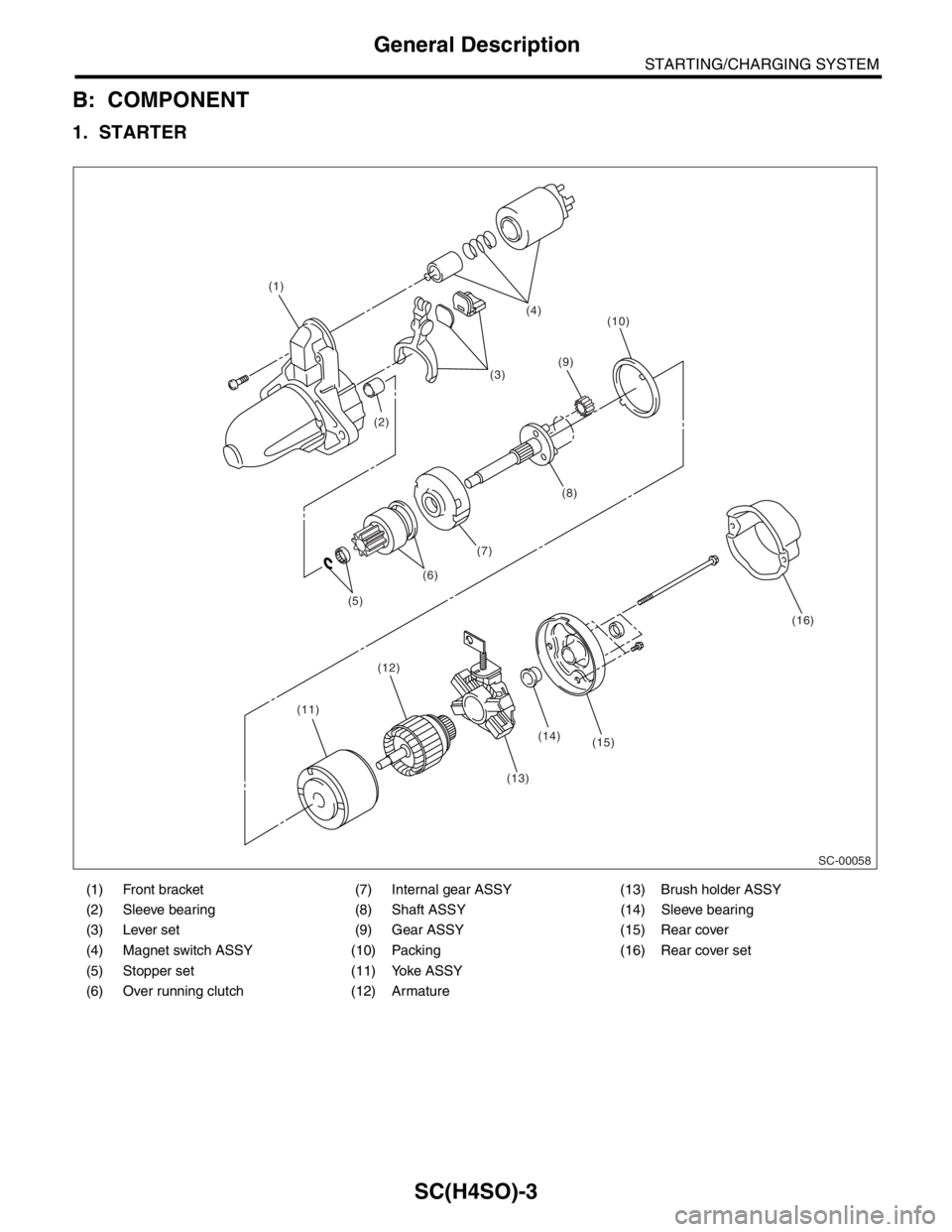
1. STARTER
(1) Front bracket (7) Internal gear ASSY (13) Brush holder ASSY
(2) Sleeve bearing (8) Shaft ASSY (14) Sleeve bearing
(3) Lever set (9) Gear ASSY (15) Rear cover
(4) Magnet switch ASSY (10) Packing (16) Rear cover set
(5) Stopper set (11) Yoke ASSY
(6) Over running clutch (12) Armature
SC-00058
(14) (1)
(2)(3)(4)
(10)
(11)(12)
(13)(15)(16) (5)(6)(7)(8) (9)
Page 1079 of 2870
SC(H4SO)-4
STARTING/CHARGING SYSTEM
General Description
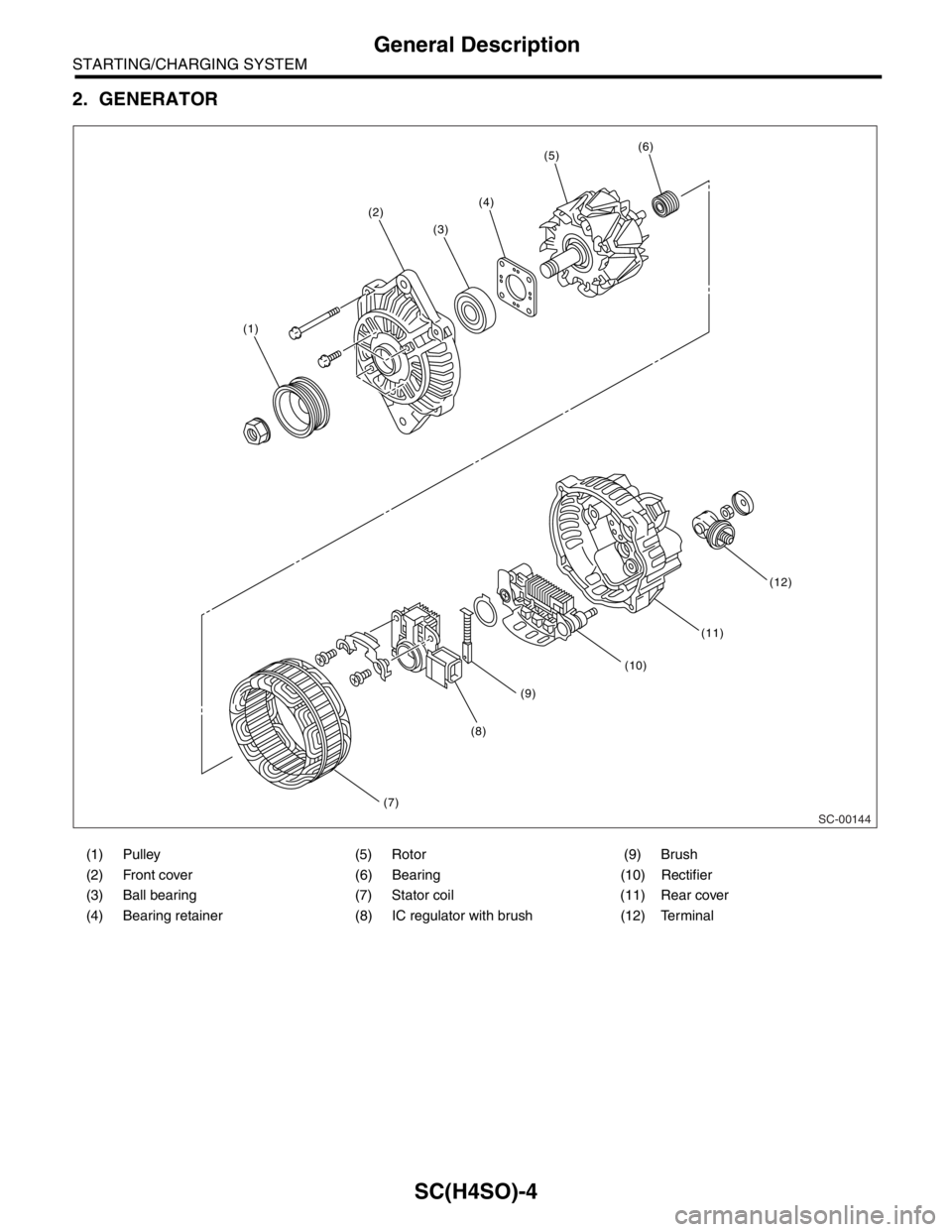
2. GENERATOR
(1) Pulley (5) Rotor (9) Brush
(2) Front cover (6) Bearing (10) Rectifier
(3) Ball bearing (7) Stator coil (11) Rear cover
(4) Bearing retainer (8) IC regulator with brush (12) Terminal
SC-00144
(1)
(2)
(7)
(8)
(9)
(10)
(11)
(12)
(3)
(4)
(5)(6)
Page 1080 of 2870
SC(H4SO)-5
STARTING/CHARGING SYSTEM
General Description
C: CAUTION
Wear working clothing, including a cap, protec-
tive goggles, and protective shoes during opera-
tion.
Remove contamination including dirt and corro-
sion before removal, installation or disassembly.
Keep the disassembled parts in order and pro-
tect them from dust or dirt.
Before removal, installation or disassembly, be
sure to clarify the failure. Avoid unnecessary re-
moval, installation, disassembly, and replacement.
Be careful not to burn yourself, because each
part in the vehicle is hot after running.
Be sure to tighten fasteners including bolts and
nuts to the specified torque.
Place shop jacks or rigid racks at the specified
points.
Before disconnecting electrical connectors of
sensors or units, be sure to disconnect the ground
cable from battery.
Trending: manual transmission, automatic transmission fluid, brake, light, open hood, coolant level, bolt pattern

