SUBARU FORESTER 2004 Service Repair Manual
Manufacturer: SUBARU, Model Year: 2004, Model line: FORESTER, Model: SUBARU FORESTER 2004Pages: 2870, PDF Size: 38.67 MB
Page 1051 of 2870
LU(H4SO)-23
LUBRICATION
Engine Oil Filter
8. Engine Oil Filter
A: REMOVAL
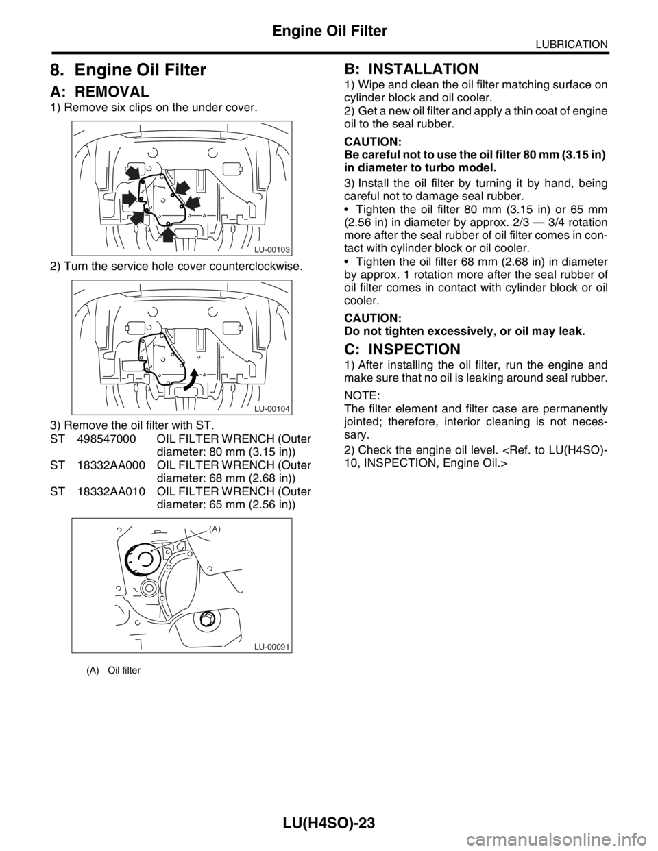
1) Remove six clips on the under cover.
2) Turn the service hole cover counterclockwise.
3) Remove the oil filter with ST.
ST 498547000 OIL FILTER WRENCH (Outer
diameter: 80 mm (3.15 in))
ST 18332AA000 OIL FILTER WRENCH (Outer
diameter: 68 mm (2.68 in))
ST 18332AA010 OIL FILTER WRENCH (Outer
diameter: 65 mm (2.56 in))
B: INSTALLATION
1) Wipe and clean the oil filter matching surface on
cylinder block and oil cooler.
2) Get a new oil filter and apply a thin coat of engine
oil to the seal rubber.
CAUTION:
Be careful not to use the oil filter 80 mm (3.15 in)
in diameter to turbo model.
3) Install the oil filter by turning it by hand, being
careful not to damage seal rubber.
Tighten the oil filter 80 mm (3.15 in) or 65 mm
(2.56 in) in diameter by approx. 2/3 — 3/4 rotation
more after the seal rubber of oil filter comes in con-
tact with cylinder block or oil cooler.
Tighten the oil filter 68 mm (2.68 in) in diameter
by approx. 1 rotation more after the seal rubber of
oil filter comes in contact with cylinder block or oil
cooler.
CAUTION:
Do not tighten excessively, or oil may leak.
C: INSPECTION
1) After installing the oil filter, run the engine and
make sure that no oil is leaking around seal rubber.
NOTE:
The filter element and filter case are permanently
jointed; therefore, interior cleaning is not neces-
sary.
2) Check the engine oil level.
(A) Oil filter
LU-00103
LU-00104
LU-00091
(A)
Page 1052 of 2870

LU(H4SO)-24
LUBRICATION
Engine Lubrication System Trouble in General
9. Engine Lubrication System Trouble in General
A: INSPECTION
Before performing diagnostics, make sure that the engine oil level is correct and no oil leakage exists.
Trouble Possible cause Corrective action
1. Warning light remains
on.1) Oil pressure switch
failureCracked diaphragm or oil leakage within switch Replace.
Broken spring or seized contacts Replace.
2) Low oil pressureClogged oil filter Replace.
Malfunction of oil by-pass valve of oil filter Clean or replace.
Malfunction of oil relief valve of oil pump Clean or replace.
Clogged oil passage Clean.
Excessive tip clearance and side clearance of oil
pump rotor and gearReplace.
Clogged oil strainer or broken pipe Clean or replace.
3) No oil pressureInsufficient engine oil Replenish.
Broken pipe of oil strainer Replace.
Stuck oil pump rotor Replace.
2. Warning light does
not go on.1) Malfunction of combination meter Replace.
2) Poor contact of switch contact points Replace.
3) Disconnection of wiring Repair.
3. Warning light flickers
momentarily.1) Poor contact at terminals Repair.
2) Defective wiring harness Repair.
3) Low oil pressureCheck for the same
possible causes as
listed in 1. — 2).
Page 1053 of 2870
FUJI HEAVY INDUSTRIES LTD. G8080GE2
2004 FORESTER SERVICE MANUAL QUICK REFERENCE INDEX
ENGINE SECTION 1
This service manual has been prepared
to provide SUBARU service personnel
with the necessary information and data
for the correct maintenance and repair
of SUBARU vehicles.
This manual includes the procedures
for maintenance, disassembling, reas-
sembling, inspection and adjustment of
components and diagnostics for guid-
ance of experienced mechanics.
Please peruse and utilize this manual
fully to ensure complete repair work for
satisfying our customers by keeping
their vehicle in optimum condition.
When replacement of parts during
repair work is needed, be sure to use
SUBARU genuine parts.
All information, illustration and specifi-
cations contained in this manual are
based on the latest product information
available at the time of publication
approval.FUEL INJECTION (FUEL SYSTEM) FU(H4SO)
EMISSION CONTROL
(AUX. EMISSION CONTROL DEVICE)EC(H4SO)
INTAKE (INDUCTION) IN(H4SO)
MECHANICAL ME(H4SO)
EXHAUST EX(H4SO)
COOLING CO(H4SO)
LUBRICATION LU(H4SO)
SPEED CONTROL SYSTEM SP(H4SO)
IGNITION IG(H4SO)
STARTING/CHARGING SYSTEM SC(H4SO)
ENGINE (DIAGNOSTIC) EN(H4SO)
Page 1054 of 2870

SPEED CONTROL SYSTEM
SP(H4SO)
Page
1. General Description ....................................................................................2
2. Accelerator Pedal ........................................................................................4
3. Accelerator Control Cable ...........................................................................9
Page 1055 of 2870
SP(H4SO)-2
SPEED CONTROL SYSTEM
General Description
1. General Description
A: SPECIFICATION
B: COMPONENT
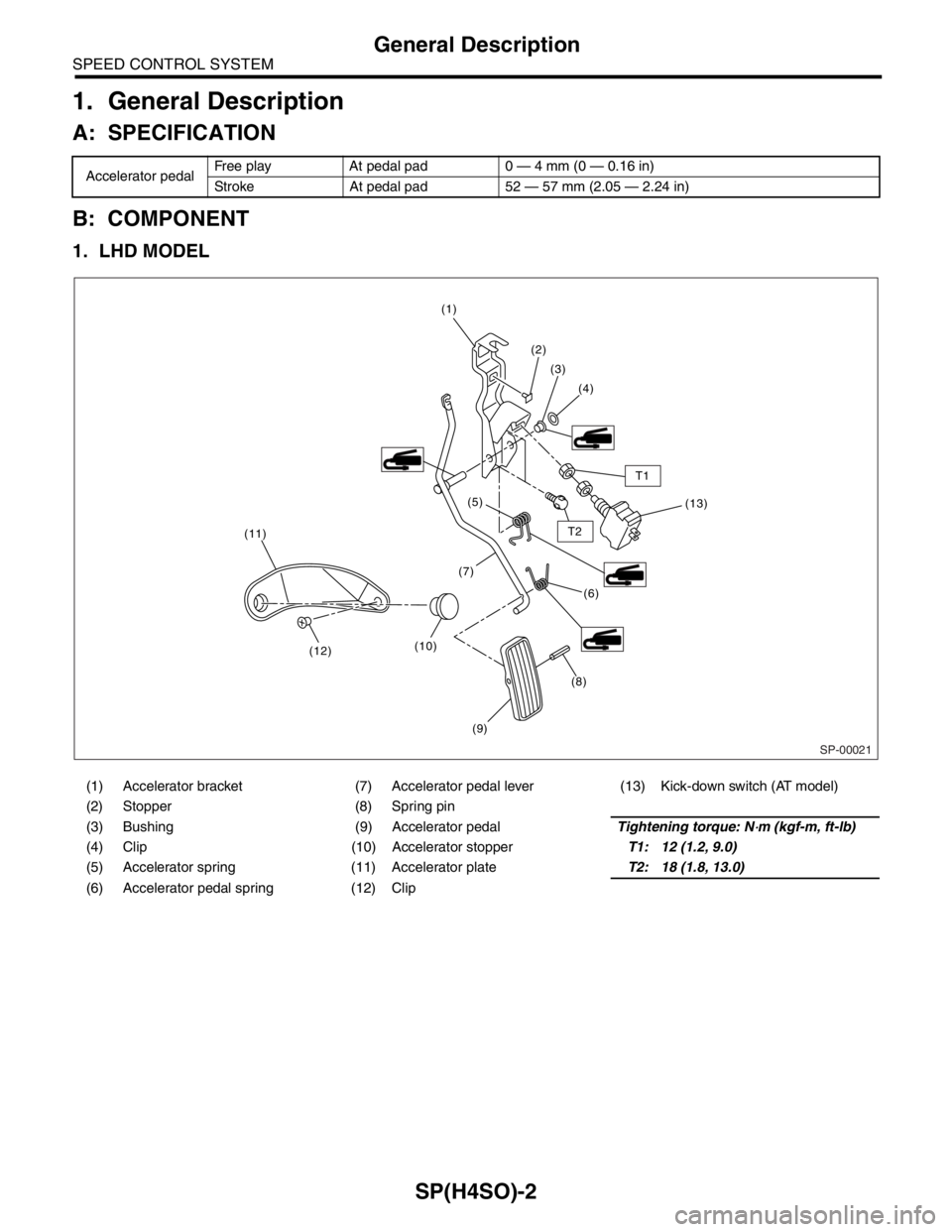
1. LHD MODEL
Accelerator pedalFree play At pedal pad 0 — 4 mm (0 — 0.16 in)
Stroke At pedal pad 52 — 57 mm (2.05 — 2.24 in)
(1) Accelerator bracket (7) Accelerator pedal lever (13) Kick-down switch (AT model)
(2) Stopper (8) Spring pin
(3) Bushing (9) Accelerator pedalTightening torque: N
⋅m (kgf-m, ft-lb)
(4) Clip (10) Accelerator stopperT1: 12 (1.2, 9.0)
(5) Accelerator spring (11) Accelerator plateT2: 18 (1.8, 13.0)
(6) Accelerator pedal spring (12) Clip
(8) (1)
(2)
(3)
(4)
(6)(13) (5)
(9) (10)(7)
(12) (11)
T2
T1
SP-00021
Page 1056 of 2870
SP(H4SO)-3
SPEED CONTROL SYSTEM
General Description
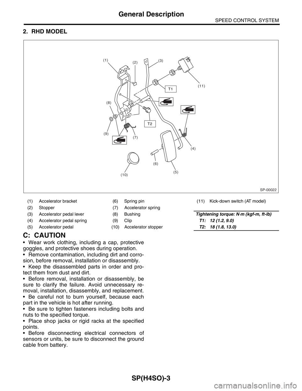
2. RHD MODEL
C: CAUTION
Wear work clothing, including a cap, protective
goggles, and protective shoes during operation.
Remove contamination, including dirt and corro-
sion, before removal, installation or disassembly.
Keep the disassembled parts in order and pro-
tect them from dust and dirt.
Before removal, installation or disassembly, be
sure to clarify the failure. Avoid unnecessary re-
moval, installation, disassembly, and replacement.
Be careful not to burn yourself, because each
part in the vehicle is hot after running.
Be sure to tighten fasteners including bolts and
nuts to the specified torque.
Place shop jacks or rigid racks at the specified
points.
Before disconnecting electrical connectors of
sensors or units, be sure to disconnect the ground
cable from battery.
(1) Accelerator bracket (6) Spring pin (11) Kick-down switch (AT model)
(2) Stopper (7) Accelerator spring
(3) Accelerator pedal lever (8) BushingTightening torque: N
⋅m (kgf-m, ft-lb)
(4) Accelerator pedal spring (9) ClipT1: 12 (1.2, 9.0)
(5) Accelerator pedal (10) Accelerator stopperT2: 18 (1.8, 13.0)
SP-00022
(1)
(2)(3)
(11)
(8)
(7) (9)
(6)(4)
(5)
(10)
T1
T2
Page 1057 of 2870
SP(H4SO)-4
SPEED CONTROL SYSTEM
Accelerator Pedal
2. Accelerator Pedal
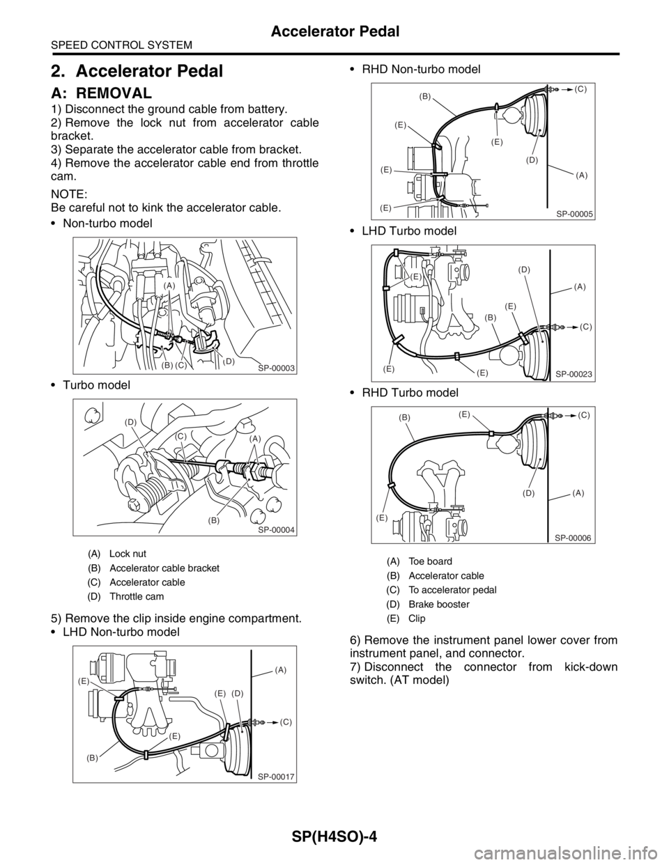
A: REMOVAL
1) Disconnect the ground cable from battery.
2) Remove the lock nut from accelerator cable
bracket.
3) Separate the accelerator cable from bracket.
4) Remove the accelerator cable end from throttle
cam.
NOTE:
Be careful not to kink the accelerator cable.
Non-turbo model
Turbo model
5) Remove the clip inside engine compartment.
LHD Non-turbo model RHD Non-turbo model
LHD Turbo model
RHD Turbo model
6) Remove the instrument panel lower cover from
instrument panel, and connector.
7) Disconnect the connector from kick-down
switch. (AT model)
(A) Lock nut
(B) Accelerator cable bracket
(C) Accelerator cable
(D) Throttle cam
(B)(D)
(C)
(A)
SP-00003
(B) (D)
(C)
(A)SP-00004
SP-00017
(A)
(B)(C) (D)
(E)
(E)
(E)
(A) Toe board
(B) Accelerator cable
(C) To accelerator pedal
(D) Brake booster
(E) Clip
(A) (B)(C)
(E)(E)(E)
(E)
(D)
SP-00005
(A) (D)
(E)
(E) (E)(C)
(B)
(E)
SP-00023
(A)
(D) (E)
(E)(B)(C)
SP-00006
Page 1058 of 2870
SP(H4SO)-5
SPEED CONTROL SYSTEM
Accelerator Pedal
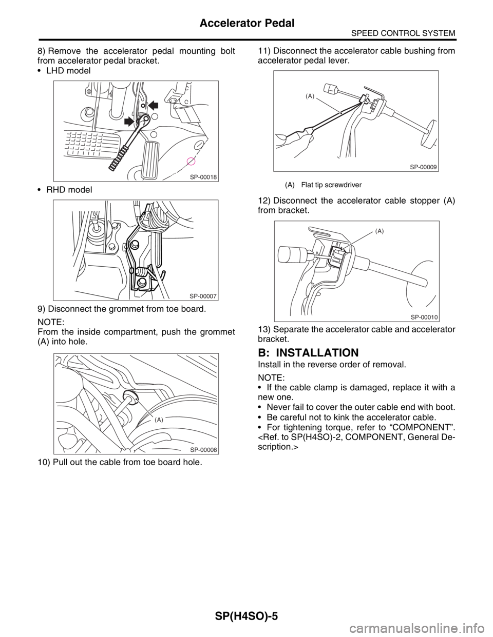
8) Remove the accelerator pedal mounting bolt
from accelerator pedal bracket.
LHD model
RHD model
9) Disconnect the grommet from toe board.
NOTE:
From the inside compartment, push the grommet
(A) into hole.
10) Pull out the cable from toe board hole.11) Disconnect the accelerator cable bushing from
accelerator pedal lever.
12) Disconnect the accelerator cable stopper (A)
from bracket.
13) Separate the accelerator cable and accelerator
bracket.
B: INSTALLATION
Install in the reverse order of removal.
NOTE:
If the cable clamp is damaged, replace it with a
new one.
Never fail to cover the outer cable end with boot.
Be careful not to kink the accelerator cable.
For tightening torque, refer to “COMPONENT”.
SP-00018
SP-00007
SP-00008
(A)
(A) Flat tip screwdriver
SP-00009
(A)
SP-00010
(A)
Page 1059 of 2870
SP(H4SO)-6
SPEED CONTROL SYSTEM
Accelerator Pedal
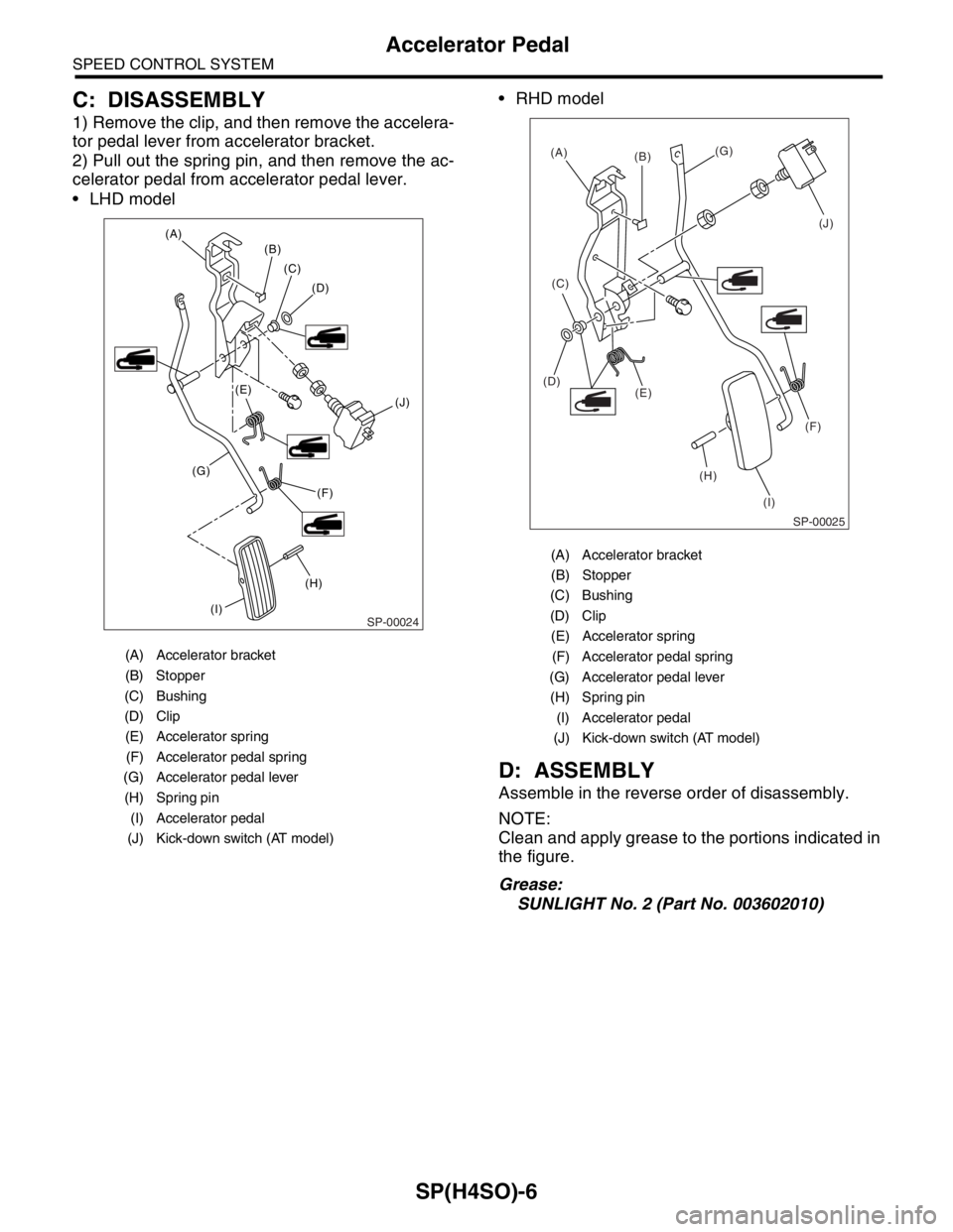
C: DISASSEMBLY
1) Remove the clip, and then remove the accelera-
tor pedal lever from accelerator bracket.
2) Pull out the spring pin, and then remove the ac-
celerator pedal from accelerator pedal lever.
LHD model RHD model
D: ASSEMBLY
Assemble in the reverse order of disassembly.
NOTE:
Clean and apply grease to the portions indicated in
the figure.
Grease:
SUNLIGHT No. 2 (Part No. 003602010)
(A) Accelerator bracket
(B) Stopper
(C) Bushing
(D) Clip
(E) Accelerator spring
(F) Accelerator pedal spring
(G) Accelerator pedal lever
(H) Spring pin
(I) Accelerator pedal
(J) Kick-down switch (AT model)
SP-00024
(H) (A)
(B)
(C)
(D)
(F)(J) (E)
(I) (G)
(A) Accelerator bracket
(B) Stopper
(C) Bushing
(D) Clip
(E) Accelerator spring
(F) Accelerator pedal spring
(G) Accelerator pedal lever
(H) Spring pin
(I) Accelerator pedal
(J) Kick-down switch (AT model)
SP-00025
(A)
(B)(G)
(J)
(C)
(E) (D)
(H)(F)
(I)
Page 1060 of 2870
SP(H4SO)-7
SPEED CONTROL SYSTEM
Accelerator Pedal
E: INSPECTION
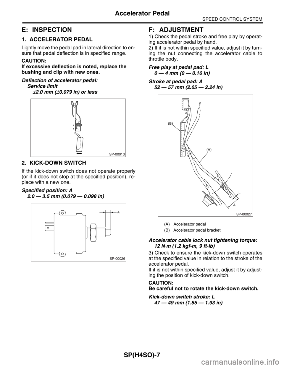
1. ACCELERATOR PEDAL
Lightly move the pedal pad in lateral direction to en-
sure that pedal deflection is in specified range.
CAUTION:
If excessive deflection is noted, replace the
bushing and clip with new ones.
Deflection of accelerator pedal:
Service limit
±2.0 mm (±0.079 in) or less
2. KICK-DOWN SWITCH
If the kick-down switch does not operate properly
(or if it does not stop at the specified position), re-
place with a new one.
Specified position: A
2.0 — 3.5 mm (0.079 — 0.098 in)
F: ADJUSTMENT
1) Check the pedal stroke and free play by operat-
ing accelerator pedal by hand.
2) If it is not within specified value, adjust it by turn-
ing the nut connecting the accelerator cable to
throttle body.
Free play at pedal pad: L
0 — 4 mm (0 — 0.16 in)
Stroke at pedal pad: A
52 — 57 mm (2.05 — 2.24 in)
Accelerator cable lock nut tightening torque:
12 N
⋅m (1.2 kgf-m, 9 ft-lb)
3) Check to ensure the kick-down switch operates
at the specified value in relation to the stroke of the
accelerator pedal.
If it is not within specified value, adjust it by adjust-
ing the position of kick-down switch.
CAUTION:
Be careful not to rotate the kick-down switch.
Kick-down switch stroke: L
47 — 49 mm (1.85 — 1.93 in)
SP-00013
SP-00026
A
(A) Accelerator pedal
(B) Accelerator pedal bracket
SP-00027
(A)
L
A (B)