SUBARU LEGACY 1999 Service Repair Manual
LEGACY 1999
SUBARU
SUBARU
https://www.carmanualsonline.info/img/17/57435/w960_57435-0.png
SUBARU LEGACY 1999 Service Repair Manual
Trending: air conditioning, tire type, timing belt, wiper blades, run flat, roof, wiring diagram
Page 391 of 1456
3) Ensure that there is no air flow when hose is
tilted greater than 90É.9. Fuel Sub Meter Unit
A: REMOVAL AND INSTALLATION
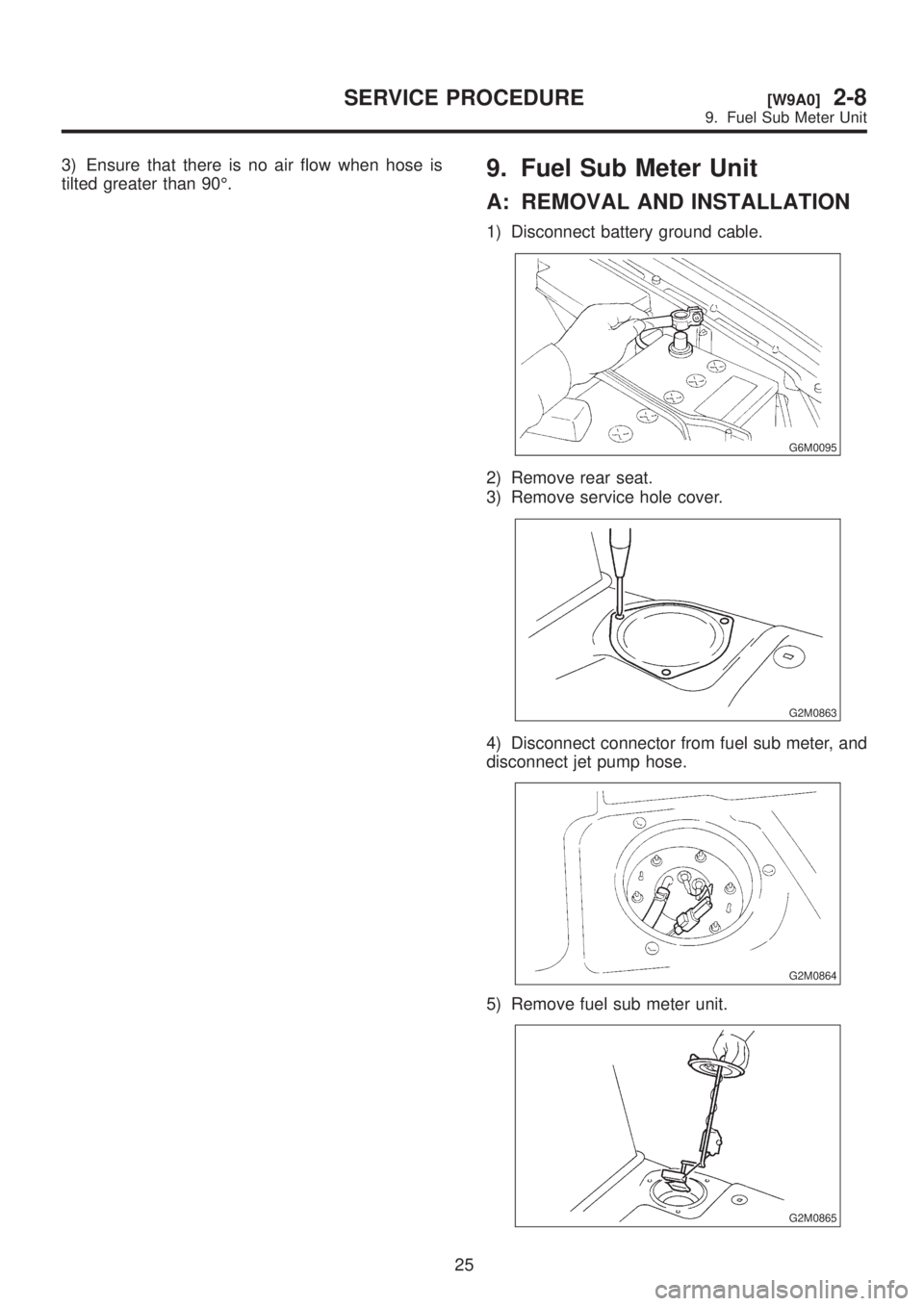
1) Disconnect battery ground cable.
G6M0095
2) Remove rear seat.
3) Remove service hole cover.
G2M0863
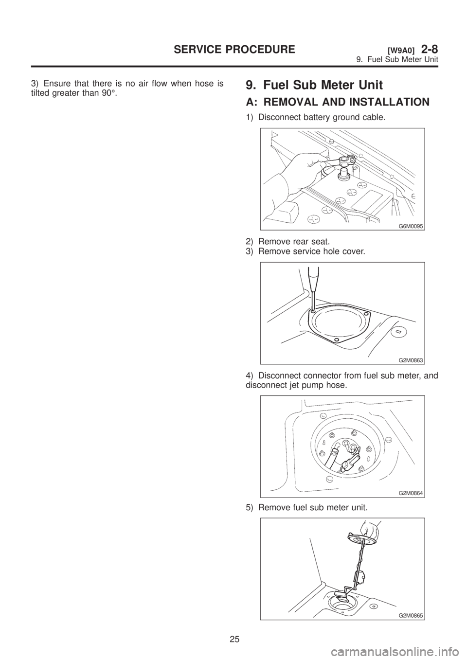
4) Disconnect connector from fuel sub meter, and
disconnect jet pump hose.
G2M0864
5) Remove fuel sub meter unit.
G2M0865
25
[W9A0]2-8SERVICE PROCEDURE
9. Fuel Sub Meter Unit
Page 392 of 1456
3) Ensure that there is no air flow when hose is
tilted greater than 90É.9. Fuel Sub Meter Unit
A: REMOVAL AND INSTALLATION
1) Disconnect battery ground cable.
G6M0095
2) Remove rear seat.
3) Remove service hole cover.
G2M0863
4) Disconnect connector from fuel sub meter, and
disconnect jet pump hose.
G2M0864
5) Remove fuel sub meter unit.
G2M0865
25
[W9A0]2-8SERVICE PROCEDURE
9. Fuel Sub Meter Unit
Page 393 of 1456
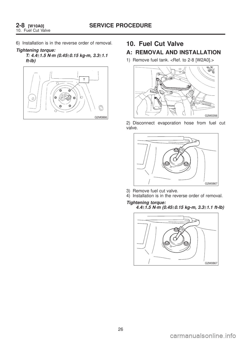
6) Installation is in the reverse order of removal.
Tightening torque:
T: 4.4
±1.5 N´m (0.45±0.15 kg-m, 3.3±1.1
ft-lb)
G2M0866
10. Fuel Cut Valve
A: REMOVAL AND INSTALLATION
1) Remove fuel tank.
G2M0356
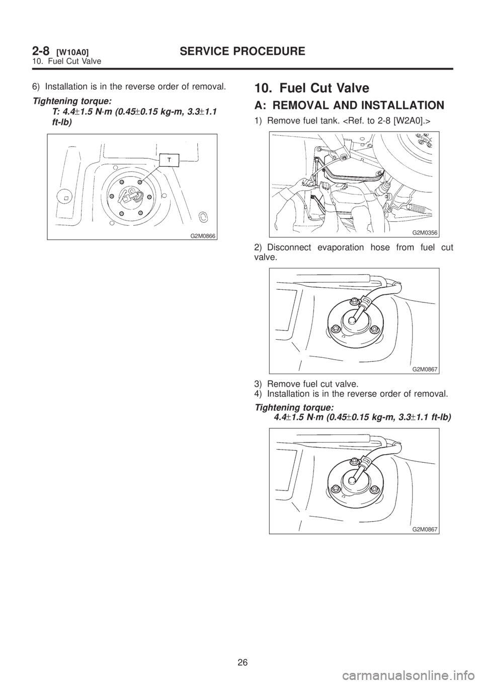
2) Disconnect evaporation hose from fuel cut
valve.
G2M0867
3) Remove fuel cut valve.
4) Installation is in the reverse order of removal.
Tightening torque:
4.4
±1.5 N´m (0.45±0.15 kg-m, 3.3±1.1 ft-lb)
G2M0867
26
2-8[W10A0]SERVICE PROCEDURE
10. Fuel Cut Valve
Page 394 of 1456
6) Installation is in the reverse order of removal.
Tightening torque:
T: 4.4
±1.5 N´m (0.45±0.15 kg-m, 3.3±1.1
ft-lb)
G2M0866
10. Fuel Cut Valve
A: REMOVAL AND INSTALLATION
1) Remove fuel tank.
G2M0356
2) Disconnect evaporation hose from fuel cut
valve.
G2M0867
3) Remove fuel cut valve.
4) Installation is in the reverse order of removal.
Tightening torque:
4.4
±1.5 N´m (0.45±0.15 kg-m, 3.3±1.1 ft-lb)
G2M0867
26
2-8[W10A0]SERVICE PROCEDURE
10. Fuel Cut Valve
Page 395 of 1456
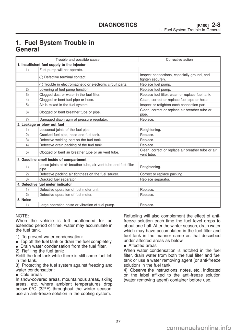
1. Fuel System Trouble in
General
Trouble and possible cause Corrective action
1. Insufficient fuel supply to the injector
1) Fuel pump will not operate.
qDefective terminal contact.Inspect connections, especially ground, and
tighten securely.
qTrouble in electromagnetic or electronic circuit parts. Replace fuel pump.
2) Lowering of fuel pump function. Replace fuel pump.
3) Clogged dust or water in the fuel filter. Replace fuel filter, clean or replace fuel tank.
4) Clogged or bent fuel pipe or hose. Clean, correct or replace fuel pipe or hose.
5) Air is mixed in the fuel system. Inspect or retighten each connection part.
6) Clogged or bent breather tube or pipe.Clean, correct or replace air breather tube or
pipe.
7) Damaged diaphragm of pressure regulator. Replace.
2. Leakage or blow out fuel
1) Loosened joints of the fuel pipe. Retightening.
2) Cracked fuel pipe, hose and fuel tank. Replace.
3) Defective welding part on the fuel tank. Replace.
4) Defective drain packing of the fuel tank. Replace.
5) Clogged or bent air breather tube or air vent tube.Clean, correct or replace air breather tube or air
vent tube.
3.Gasoline smell inside of compartment
1)Loose joints at air breather tube, air vent tube and fuel filler
pipe.Retightening.
2) Defective packing air tightness on the fuel saucer. Correct or replace packing.
3) Cracked fuel separator. Replace separator.
4. Defective fuel meter indicator
1) Defective operation of fuel meter unit. Replace.
2) Defective operation of fuel meter. Replace.
5. Noise
1) Large operation noise or vibration of fuel pump. Replace.
NOTE:
When the vehicle is left unattended for an
extended period of time, water may accumulate in
the fuel tank.
1) To prevent water condensation:
ITop off the fuel tank or drain the fuel completely.
IDrain water condensation from the fuel filter.
2) Refilling the fuel tank:
Refill the fuel tank while there is still some fuel left
in the tank.
3) Protecting the fuel system against freezing and
water condensation:
ICold areas
In snow-covered areas, mountainous areas, skiing
areas, etc. where ambient temperatures drop
below 0ÉC (32ÉF) throughout the winter season,
use an anti-freeze solution in the cooling system.Refueling will also complement the effect of anti-
freeze solution each time the fuel level drops to
about one-half. After the winter season, drain water
which may have accumulated in the fuel filter and
fuel tank in the manner same as that described
under affected areas as below.
IAffected areas
When water condensation is notched in the fuel
filter, drain water from both the fuel filter and fuel
tank or use a water removing agent (or anti-freeze
solution) in the fuel tank.
4) Observe the instructions, notes, etc., indicated
on the label affixed to the anti-freeze solution
(water removing agent) container before use.
27
[K100]2-8DIAGNOSTICS
1. Fuel System Trouble in General
Page 396 of 1456
Page 397 of 1456
1. Exhaust System
A: 2200 cc MODEL
B2M1982A
2
2-9[C1A0]COMPONENT PARTS
1. Exhaust System
Page 398 of 1456
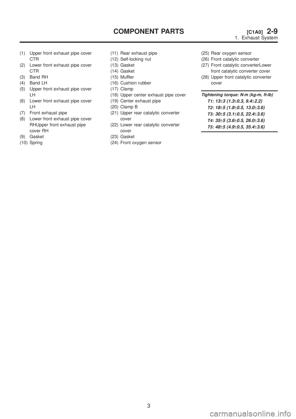
(1) Upper front exhaust pipe cover
CTR
(2) Lower front exhaust pipe cover
CTR
(3) Band RH
(4) Band LH
(5) Upper front exhaust pipe cover
LH
(6) Lower front exhaust pipe cover
LH
(7) Front exhaust pipe
(8) Lower front exhaust pipe cover
RHUpper front exhaust pipe
cover RH
(9) Gasket
(10) Spring(11) Rear exhaust pipe
(12) Self-locking nut
(13) Gasket
(14) Gasket
(15) Muffler
(16) Cushion rubber
(17) Clamp
(18) Upper center exhaust pipe cover
(19) Center exhaust pipe
(20) Clamp B
(21) Upper rear catalytic converter
cover
(22) Lower rear catalytic converter
cover
(23) Gasket
(24) Front oxygen sensor(25) Rear oxygen sensor
(26) Front catalytic converter
(27) Front catalytic converterLower
front catalytic converter cover
(28) Upper front catalytic converter
cover
Tightening torque: N´m (kg-m, ft-lb)
T1:
13±3 (1.3±0.3, 9.4±2.2)
T2:18±5 (1.8±0.5, 13.0±3.6)
T3:30±5 (3.1±0.5, 22.4±3.6)
T4:35±5 (3.6±0.5, 26.0±3.6)
T5:48±5 (4.9±0.5, 35.4±3.6)
3
[C1A0]2-9COMPONENT PARTS
1. Exhaust System
Page 399 of 1456
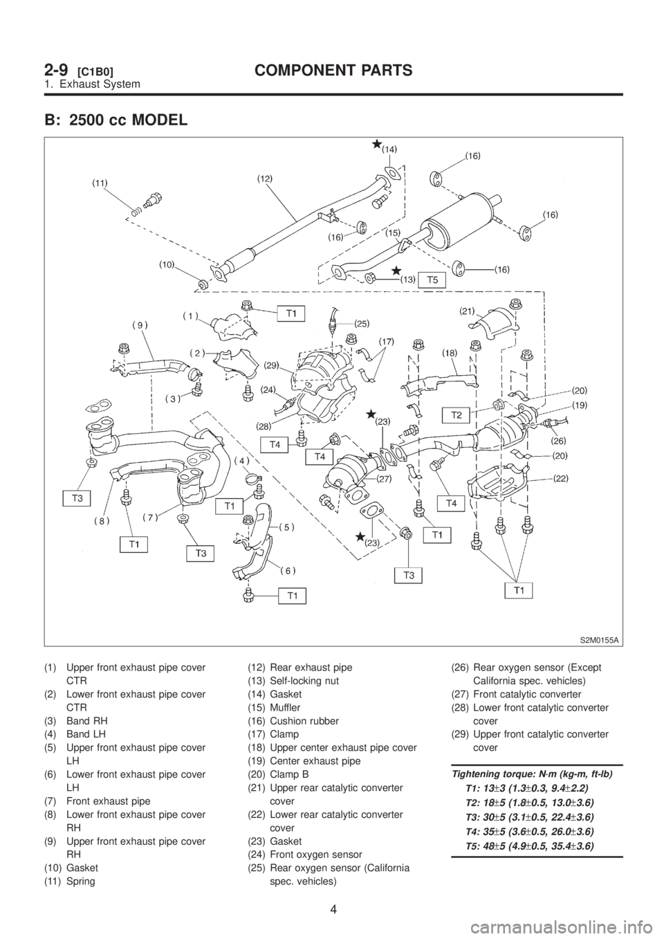
B: 2500 cc MODEL
S2M0155A
(1) Upper front exhaust pipe cover
CTR
(2) Lower front exhaust pipe cover
CTR
(3) Band RH
(4) Band LH
(5) Upper front exhaust pipe cover
LH
(6) Lower front exhaust pipe cover
LH
(7) Front exhaust pipe
(8) Lower front exhaust pipe cover
RH
(9) Upper front exhaust pipe cover
RH
(10) Gasket
(11) Spring(12) Rear exhaust pipe
(13) Self-locking nut
(14) Gasket
(15) Muffler
(16) Cushion rubber
(17) Clamp
(18) Upper center exhaust pipe cover
(19) Center exhaust pipe
(20) Clamp B
(21) Upper rear catalytic converter
cover
(22) Lower rear catalytic converter
cover
(23) Gasket
(24) Front oxygen sensor
(25) Rear oxygen sensor (California
spec. vehicles)(26) Rear oxygen sensor (Except
California spec. vehicles)
(27) Front catalytic converter
(28) Lower front catalytic converter
cover
(29) Upper front catalytic converter
cover
Tightening torque: N´m (kg-m, ft-lb)
T1:
13±3 (1.3±0.3, 9.4±2.2)
T2:18±5 (1.8±0.5, 13.0±3.6)
T3:30±5 (3.1±0.5, 22.4±3.6)
T4:35±5 (3.6±0.5, 26.0±3.6)
T5:48±5 (4.9±0.5, 35.4±3.6)
4
2-9[C1B0]COMPONENT PARTS
1. Exhaust System
Page 400 of 1456
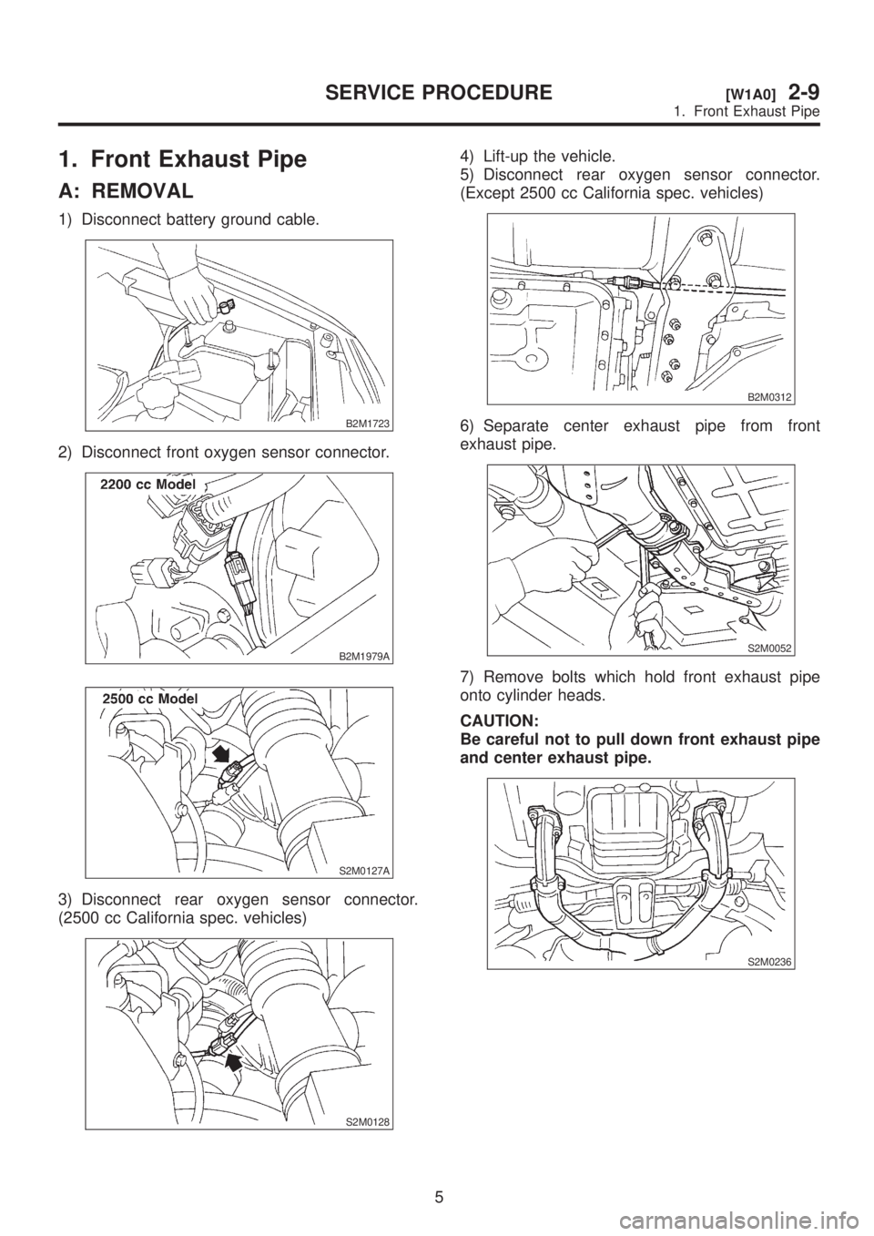
1. Front Exhaust Pipe
A: REMOVAL
1) Disconnect battery ground cable.
B2M1723
2) Disconnect front oxygen sensor connector.
B2M1979A
S2M0127A
3) Disconnect rear oxygen sensor connector.
(2500 cc California spec. vehicles)
S2M0128
4) Lift-up the vehicle.
5) Disconnect rear oxygen sensor connector.
(Except 2500 cc California spec. vehicles)
B2M0312
6) Separate center exhaust pipe from front
exhaust pipe.
S2M0052
7) Remove bolts which hold front exhaust pipe
onto cylinder heads.
CAUTION:
Be careful not to pull down front exhaust pipe
and center exhaust pipe.
S2M0236
5
[W1A0]2-9SERVICE PROCEDURE
1. Front Exhaust Pipe
Trending: change oil, open gas tank, checking oil, oil pump, fuel cap release, maintenance schedule, washer fluid

![SUBARU LEGACY 1999 Service Repair Manual 1. Exhaust System
A: 2200 cc MODEL
B2M1982A
2
2-9[C1A0]COMPONENT PARTS
1. Exhaust System SUBARU LEGACY 1999 Service Repair Manual 1. Exhaust System
A: 2200 cc MODEL
B2M1982A
2
2-9[C1A0]COMPONENT PARTS
1. Exhaust System](/img/17/57435/w960_57435-396.png)


