SUBARU LEGACY 1999 Service Repair Manual
Manufacturer: SUBARU, Model Year: 1999, Model line: LEGACY, Model: SUBARU LEGACY 1999Pages: 1456, PDF Size: 59.93 MB
Page 381 of 1456
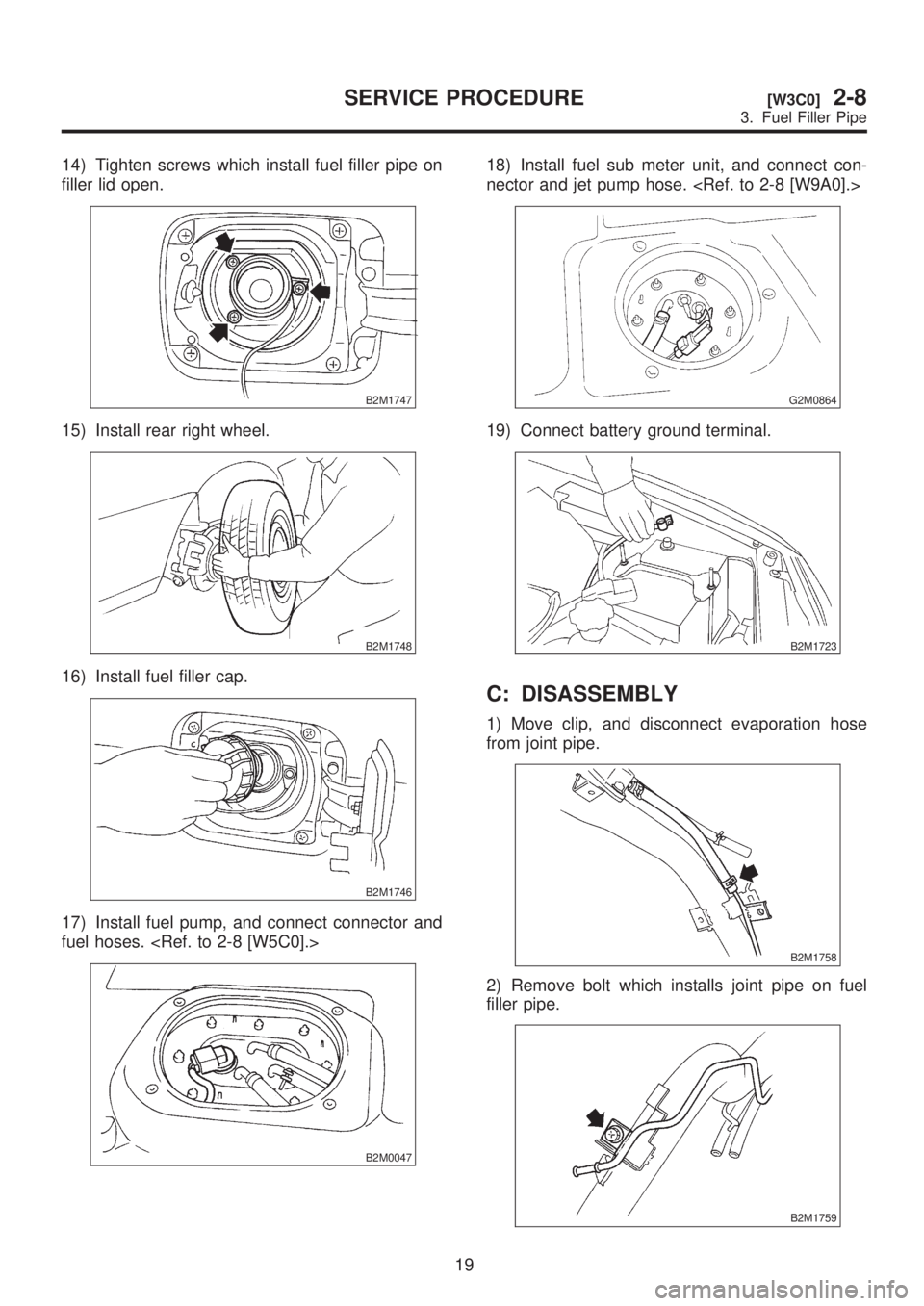
14) Tighten screws which install fuel filler pipe on
filler lid open.
B2M1747
15) Install rear right wheel.
B2M1748
16) Install fuel filler cap.
B2M1746
17) Install fuel pump, and connect connector and
fuel hoses.
B2M0047
18) Install fuel sub meter unit, and connect con-
nector and jet pump hose.
G2M0864
19) Connect battery ground terminal.
B2M1723
C: DISASSEMBLY
1) Move clip, and disconnect evaporation hose
from joint pipe.
B2M1758
2) Remove bolt which installs joint pipe on fuel
filler pipe.
B2M1759
19
[W3C0]2-8SERVICE PROCEDURE
3. Fuel Filler Pipe
Page 382 of 1456
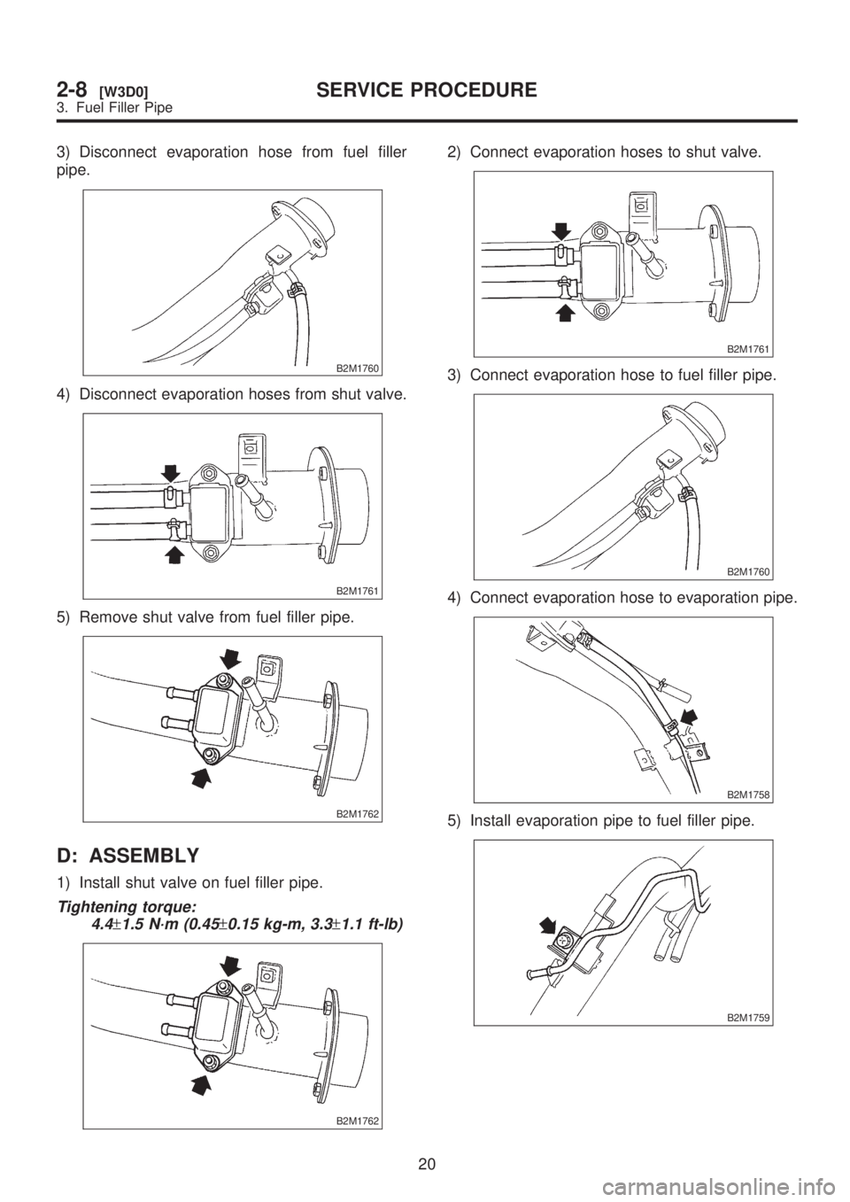
3) Disconnect evaporation hose from fuel filler
pipe.
B2M1760
4) Disconnect evaporation hoses from shut valve.
B2M1761
5) Remove shut valve from fuel filler pipe.
B2M1762
D: ASSEMBLY
1) Install shut valve on fuel filler pipe.
Tightening torque:
4.4
±1.5 N´m (0.45±0.15 kg-m, 3.3±1.1 ft-lb)
B2M1762
2) Connect evaporation hoses to shut valve.
B2M1761
3) Connect evaporation hose to fuel filler pipe.
B2M1760
4) Connect evaporation hose to evaporation pipe.
B2M1758
5) Install evaporation pipe to fuel filler pipe.
B2M1759
20
2-8[W3D0]SERVICE PROCEDURE
3. Fuel Filler Pipe
Page 383 of 1456
![SUBARU LEGACY 1999 Service Repair Manual 4. Fuel Filter
A: REMOVAL
1) Release fuel pressure. <Ref. to 2-8 [W1B0].>
2) Disconnect fuel delivery hoses from fuel filter.
S2M0195
3) Remove filter from holder.
B: INSPECTION
1) Check the inside of SUBARU LEGACY 1999 Service Repair Manual 4. Fuel Filter
A: REMOVAL
1) Release fuel pressure. <Ref. to 2-8 [W1B0].>
2) Disconnect fuel delivery hoses from fuel filter.
S2M0195
3) Remove filter from holder.
B: INSPECTION
1) Check the inside of](/img/17/57435/w960_57435-382.png)
4. Fuel Filter
A: REMOVAL
1) Release fuel pressure.
2) Disconnect fuel delivery hoses from fuel filter.
S2M0195
3) Remove filter from holder.
B: INSPECTION
1) Check the inside of fuel filter for dirt and water
sediment.
2) If it is clogged, or if replacement interval has
been reached, replace it.
3) If water is found in it, shake and expel the water
from inlet port.
C: INSTALLATION
CAUTION:
IIf fuel hoses are damaged at the connecting
portion, replace it with a new one.
IIf clamps are badly damaged, replace with
new ones.
1) Installation is in the reverse order of removal.
2) Tighten hose clamp screws.
Tightening torque:
1.0+0.5/þ0N´m (0.1+0.05/þ0kg-m, 0.7+0.4/þ0ft-lb)
S2M0195
5. Fuel Pump
A: REMOVAL
1) Release fuel pressure.
2) Disconnect fuel delivery hose (A), return hose
(B) and jet pump hose (C) (AWD model only).
B2M0048B
3) Remove nuts which install fuel pump assembly
onto fuel tank.
G2M0343
4) Take off fuel pump from fuel tank.
G2M0344
21
[W5A0]2-8SERVICE PROCEDURE
5. Fuel Pump
Page 384 of 1456
![SUBARU LEGACY 1999 Service Repair Manual 4. Fuel Filter
A: REMOVAL
1) Release fuel pressure. <Ref. to 2-8 [W1B0].>
2) Disconnect fuel delivery hoses from fuel filter.
S2M0195
3) Remove filter from holder.
B: INSPECTION
1) Check the inside of SUBARU LEGACY 1999 Service Repair Manual 4. Fuel Filter
A: REMOVAL
1) Release fuel pressure. <Ref. to 2-8 [W1B0].>
2) Disconnect fuel delivery hoses from fuel filter.
S2M0195
3) Remove filter from holder.
B: INSPECTION
1) Check the inside of](/img/17/57435/w960_57435-383.png)
4. Fuel Filter
A: REMOVAL
1) Release fuel pressure.
2) Disconnect fuel delivery hoses from fuel filter.
S2M0195
3) Remove filter from holder.
B: INSPECTION
1) Check the inside of fuel filter for dirt and water
sediment.
2) If it is clogged, or if replacement interval has
been reached, replace it.
3) If water is found in it, shake and expel the water
from inlet port.
C: INSTALLATION
CAUTION:
IIf fuel hoses are damaged at the connecting
portion, replace it with a new one.
IIf clamps are badly damaged, replace with
new ones.
1) Installation is in the reverse order of removal.
2) Tighten hose clamp screws.
Tightening torque:
1.0+0.5/þ0N´m (0.1+0.05/þ0kg-m, 0.7+0.4/þ0ft-lb)
S2M0195
5. Fuel Pump
A: REMOVAL
1) Release fuel pressure.
2) Disconnect fuel delivery hose (A), return hose
(B) and jet pump hose (C) (AWD model only).
B2M0048B
3) Remove nuts which install fuel pump assembly
onto fuel tank.
G2M0343
4) Take off fuel pump from fuel tank.
G2M0344
21
[W5A0]2-8SERVICE PROCEDURE
5. Fuel Pump
Page 385 of 1456
B: INSPECTION
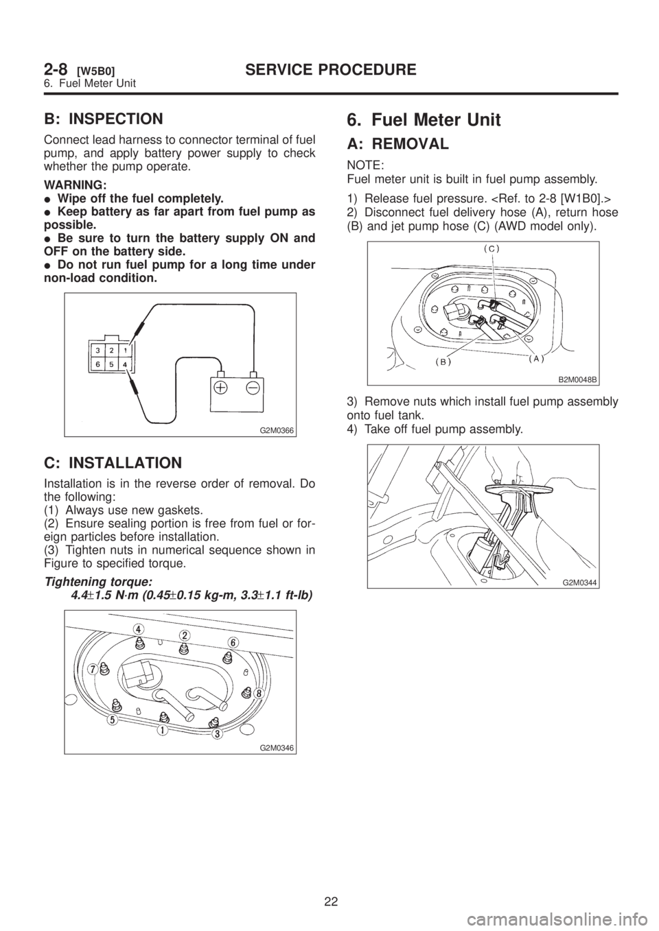
Connect lead harness to connector terminal of fuel
pump, and apply battery power supply to check
whether the pump operate.
WARNING:
IWipe off the fuel completely.
IKeep battery as far apart from fuel pump as
possible.
IBe sure to turn the battery supply ON and
OFF on the battery side.
IDo not run fuel pump for a long time under
non-load condition.
G2M0366
C: INSTALLATION
Installation is in the reverse order of removal. Do
the following:
(1) Always use new gaskets.
(2) Ensure sealing portion is free from fuel or for-
eign particles before installation.
(3) Tighten nuts in numerical sequence shown in
Figure to specified torque.
Tightening torque:
4.4
±1.5 N´m (0.45±0.15 kg-m, 3.3±1.1 ft-lb)
G2M0346
6. Fuel Meter Unit
A: REMOVAL
NOTE:
Fuel meter unit is built in fuel pump assembly.
1) Release fuel pressure.
2) Disconnect fuel delivery hose (A), return hose
(B) and jet pump hose (C) (AWD model only).
B2M0048B
3) Remove nuts which install fuel pump assembly
onto fuel tank.
4) Take off fuel pump assembly.
G2M0344
22
2-8[W5B0]SERVICE PROCEDURE
6. Fuel Meter Unit
Page 386 of 1456
B: INSPECTION
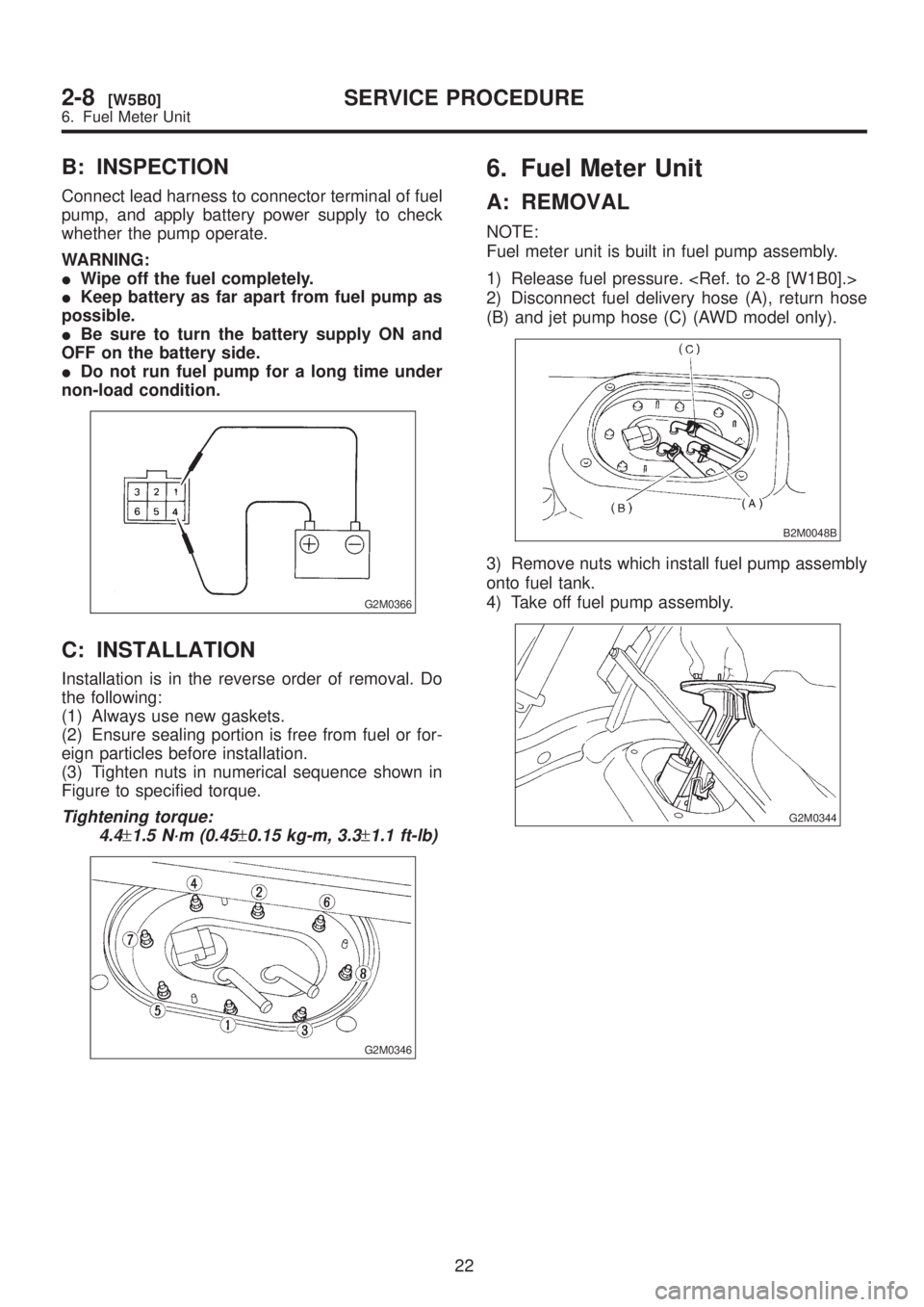
Connect lead harness to connector terminal of fuel
pump, and apply battery power supply to check
whether the pump operate.
WARNING:
IWipe off the fuel completely.
IKeep battery as far apart from fuel pump as
possible.
IBe sure to turn the battery supply ON and
OFF on the battery side.
IDo not run fuel pump for a long time under
non-load condition.
G2M0366
C: INSTALLATION
Installation is in the reverse order of removal. Do
the following:
(1) Always use new gaskets.
(2) Ensure sealing portion is free from fuel or for-
eign particles before installation.
(3) Tighten nuts in numerical sequence shown in
Figure to specified torque.
Tightening torque:
4.4
±1.5 N´m (0.45±0.15 kg-m, 3.3±1.1 ft-lb)
G2M0346
6. Fuel Meter Unit
A: REMOVAL
NOTE:
Fuel meter unit is built in fuel pump assembly.
1) Release fuel pressure.
2) Disconnect fuel delivery hose (A), return hose
(B) and jet pump hose (C) (AWD model only).
B2M0048B
3) Remove nuts which install fuel pump assembly
onto fuel tank.
4) Take off fuel pump assembly.
G2M0344
22
2-8[W5B0]SERVICE PROCEDURE
6. Fuel Meter Unit
Page 387 of 1456
B: INSTALLATION
Installation is in the reverse order of removal. Do
the following:
(1) Always use new gaskets.
(2) Ensure sealing portion is free from fuel or for-
eign particles before installation.
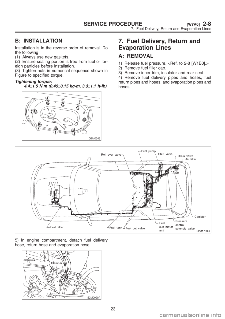
(3) Tighten nuts in numerical sequence shown in
Figure to specified torque.
Tightening torque:
4.4
±1.5 N´m (0.45±0.15 kg-m, 3.3±1.1 ft-lb)
G2M0346
7. Fuel Delivery, Return and
Evaporation Lines
A: REMOVAL
1) Release fuel pressure.
2) Remove fuel filler cap.
3) Remove inner trim, insulator and rear seat.
4) Remove fuel delivery pipes and hoses, fuel
return pipes and hoses, and evaporation pipes and
hoses.
B2M1763C
5) In engine compartment, detach fuel delivery
hose, return hose and evaporation hose.
S2M0090A
23
[W7A0]2-8SERVICE PROCEDURE
7. Fuel Delivery, Return and Evaporation Lines
Page 388 of 1456
B: INSTALLATION
Installation is in the reverse order of removal. Do
the following:
(1) Always use new gaskets.
(2) Ensure sealing portion is free from fuel or for-
eign particles before installation.
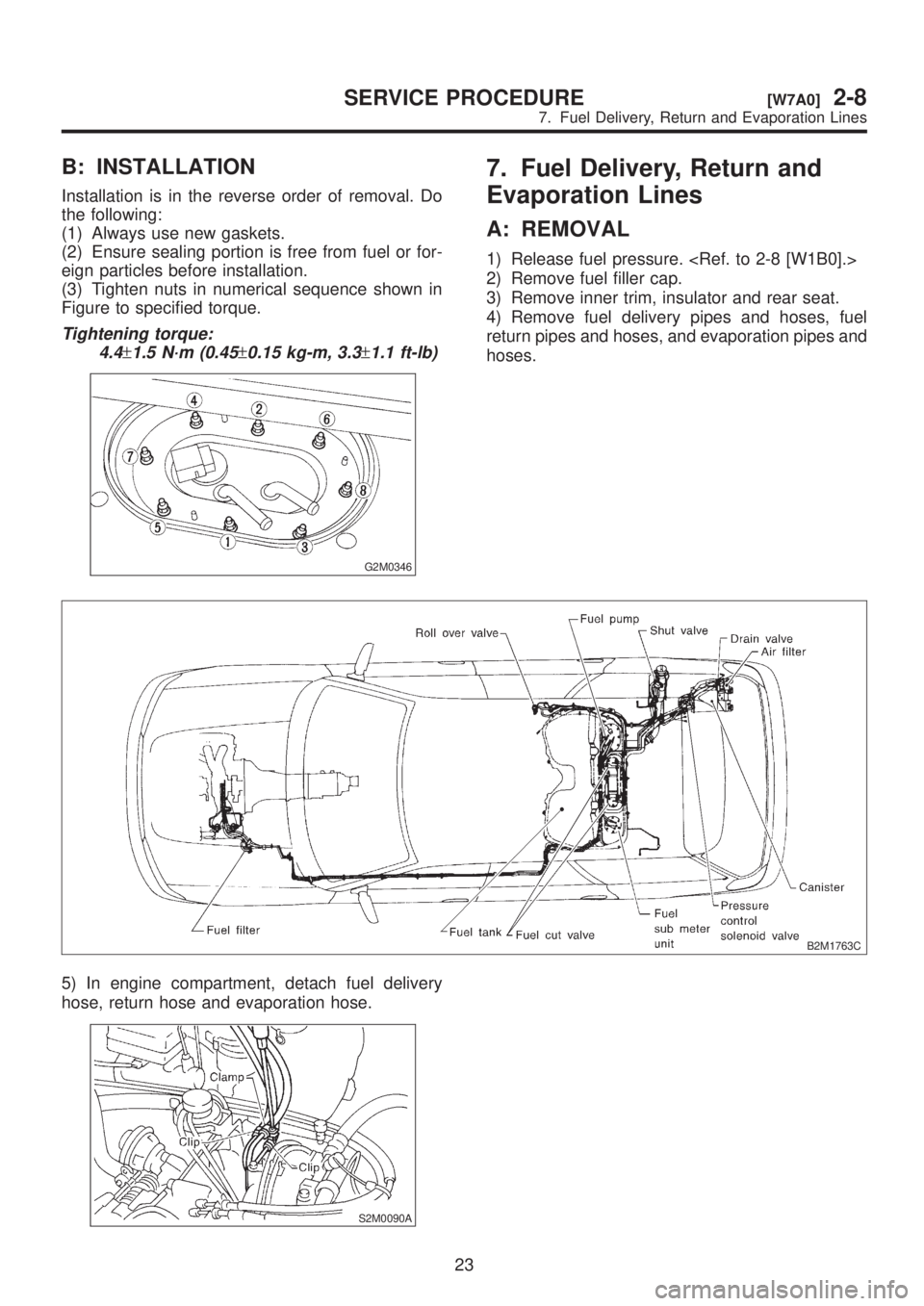
(3) Tighten nuts in numerical sequence shown in
Figure to specified torque.
Tightening torque:
4.4
±1.5 N´m (0.45±0.15 kg-m, 3.3±1.1 ft-lb)
G2M0346
7. Fuel Delivery, Return and
Evaporation Lines
A: REMOVAL
1) Release fuel pressure.
2) Remove fuel filler cap.
3) Remove inner trim, insulator and rear seat.
4) Remove fuel delivery pipes and hoses, fuel
return pipes and hoses, and evaporation pipes and
hoses.
B2M1763C
5) In engine compartment, detach fuel delivery
hose, return hose and evaporation hose.
S2M0090A
23
[W7A0]2-8SERVICE PROCEDURE
7. Fuel Delivery, Return and Evaporation Lines
Page 389 of 1456
B: INSTALLATION
Installation is in the reverse order of removal.
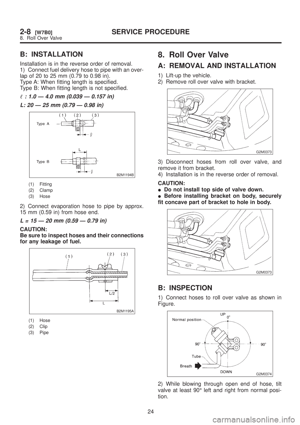
1) Connect fuel delivery hose to pipe with an over-
lap of 20 to 25 mm (0.79 to 0.98 in).
Type A: When fitting length is specified.
Type B: When fitting length is not specified.
: 1.0 Ð 4.0 mm (0.039 Ð 0.157 in)
L: 20 Ð 25 mm (0.79 Ð 0.98 in)
B2M1194B
(1) Fitting
(2) Clamp
(3) Hose
2) Connect evaporation hose to pipe by approx.
15 mm (0.59 in) from hose end.
L = 15 Ð 20 mm (0.59 Ð 0.79 in)
CAUTION:
Be sure to inspect hoses and their connections
for any leakage of fuel.
B2M1195A
(1) Hose
(2) Clip
(3) Pipe
8. Roll Over Valve
A: REMOVAL AND INSTALLATION
1) Lift-up the vehicle.
2) Remove roll over valve with bracket.
G2M0373
3) Disconnect hoses from roll over valve, and
remove it from bracket.
4) Installation is in the reverse order of removal.
CAUTION:
IDo not install top side of valve down.
IBefore installing bracket on body, securely
fit concave part of bracket to hole in body.
G2M0373
B: INSPECTION
1) Connect hoses to roll over valve as shown in
Figure.
G2M0374
2) While blowing through open end of hose, tilt
valve at least 90É left and right from normal posi-
tion.
24
2-8[W7B0]SERVICE PROCEDURE
8. Roll Over Valve
Page 390 of 1456
B: INSTALLATION
Installation is in the reverse order of removal.
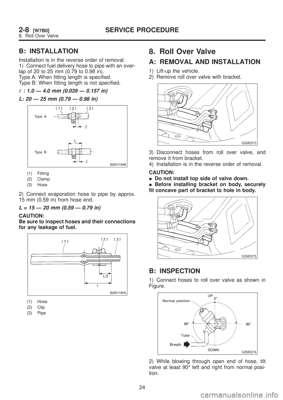
1) Connect fuel delivery hose to pipe with an over-
lap of 20 to 25 mm (0.79 to 0.98 in).
Type A: When fitting length is specified.
Type B: When fitting length is not specified.
: 1.0 Ð 4.0 mm (0.039 Ð 0.157 in)
L: 20 Ð 25 mm (0.79 Ð 0.98 in)
B2M1194B
(1) Fitting
(2) Clamp
(3) Hose
2) Connect evaporation hose to pipe by approx.
15 mm (0.59 in) from hose end.
L = 15 Ð 20 mm (0.59 Ð 0.79 in)
CAUTION:
Be sure to inspect hoses and their connections
for any leakage of fuel.
B2M1195A
(1) Hose
(2) Clip
(3) Pipe
8. Roll Over Valve
A: REMOVAL AND INSTALLATION
1) Lift-up the vehicle.
2) Remove roll over valve with bracket.
G2M0373
3) Disconnect hoses from roll over valve, and
remove it from bracket.
4) Installation is in the reverse order of removal.
CAUTION:
IDo not install top side of valve down.
IBefore installing bracket on body, securely
fit concave part of bracket to hole in body.
G2M0373
B: INSPECTION
1) Connect hoses to roll over valve as shown in
Figure.
G2M0374
2) While blowing through open end of hose, tilt
valve at least 90É left and right from normal posi-
tion.
24
2-8[W7B0]SERVICE PROCEDURE
8. Roll Over Valve