SUBARU TRIBECA 2009 1.G Service Workshop Manual
TRIBECA 2009 1.G
SUBARU
SUBARU
https://www.carmanualsonline.info/img/17/7322/w960_7322-0.png
SUBARU TRIBECA 2009 1.G Service Workshop Manual
Trending: Rear differential, lights, Ho2 sensor, wheel alignment, power steering fluid, Gnd, air cleaner
Page 1591 of 2453
FU(H6DO)-30
Rear Oxygen Sensor
FUEL INJECTION (FUEL SYSTEMS)
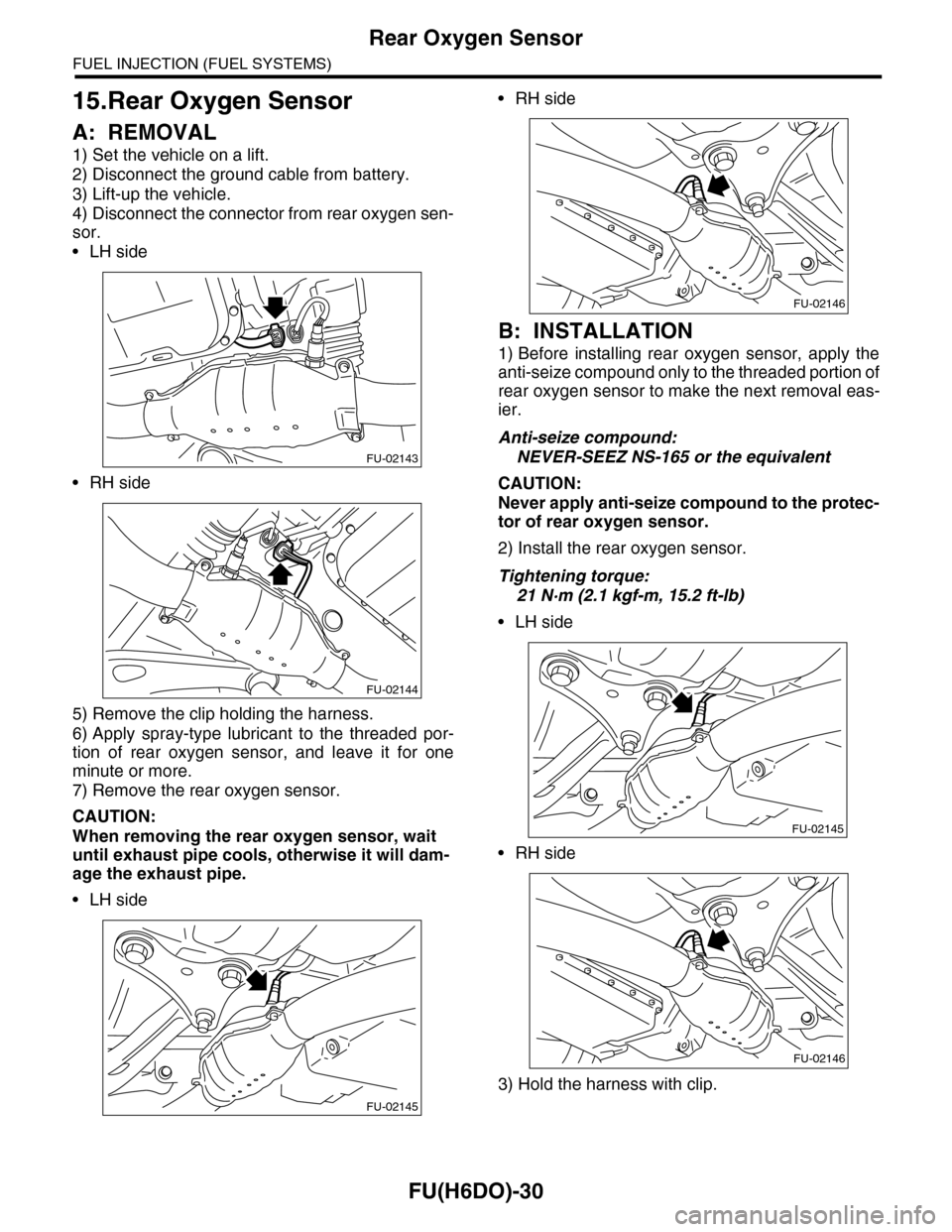
15.Rear Oxygen Sensor
A: REMOVAL
1) Set the vehicle on a lift.
2) Disconnect the ground cable from battery.
3) Lift-up the vehicle.
4) Disconnect the connector from rear oxygen sen-
sor.
•LH side
•RH side
5) Remove the clip holding the harness.
6) Apply spray-type lubricant to the threaded por-
tion of rear oxygen sensor, and leave it for one
minute or more.
7) Remove the rear oxygen sensor.
CAUTION:
When removing the rear oxygen sensor, wait
until exhaust pipe cools, otherwise it will dam-
age the exhaust pipe.
•LH side
•RH side
B: INSTALLATION
1) Before installing rear oxygen sensor, apply the
anti-seize compound only to the threaded portion of
rear oxygen sensor to make the next removal eas-
ier.
Anti-seize compound:
NEVER-SEEZ NS-165 or the equivalent
CAUTION:
Never apply anti-seize compound to the protec-
tor of rear oxygen sensor.
2) Install the rear oxygen sensor.
Tightening torque:
21 N·m (2.1 kgf-m, 15.2 ft-lb)
•LH side
•RH side
3) Hold the harness with clip.
FU-02143
FU-02144
FU-02145
FU-02146
FU-02145
FU-02146
Page 1592 of 2453
FU(H6DO)-31
Rear Oxygen Sensor
FUEL INJECTION (FUEL SYSTEMS)
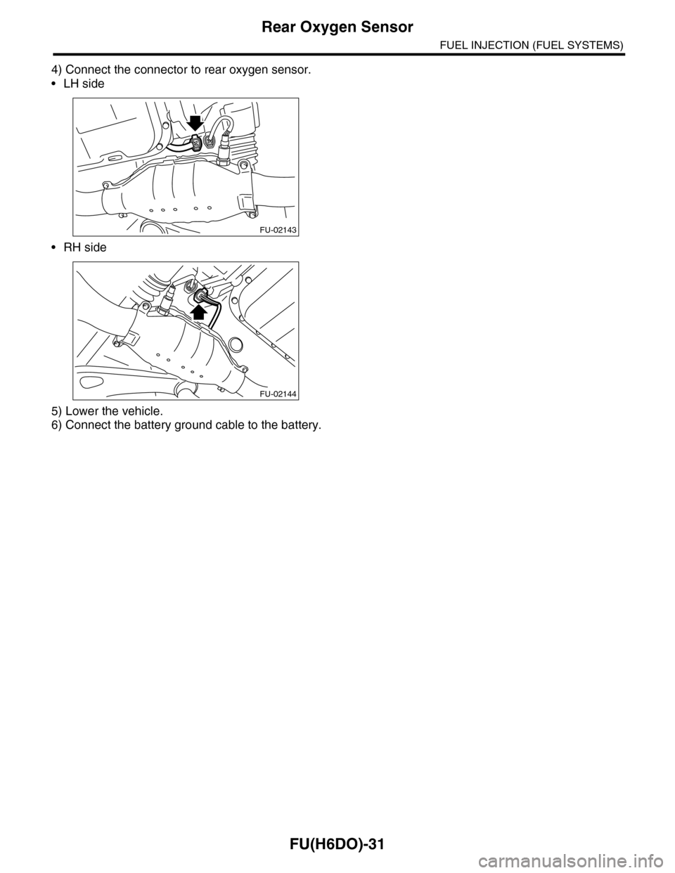
4) Connect the connector to rear oxygen sensor.
•LH side
•RH side
5) Lower the vehicle.
6) Connect the battery ground cable to the battery.
FU-02143
FU-02144
Page 1593 of 2453
FU(H6DO)-32
Engine Control Module (ECM)
FUEL INJECTION (FUEL SYSTEMS)
16.Engine Control Module (ECM)
A: REMOVAL
1) Disconnect the ground cable from battery.
2) Remove the front pillar lower trim and console
side panel lower RH of passenger's side.
3) Detach the floor mat of passenger's seat.
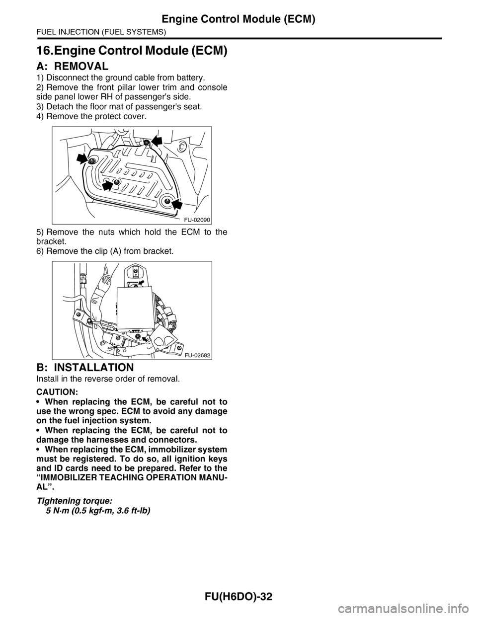
4) Remove the protect cover.
5) Remove the nuts which hold the ECM to the
bracket.
6) Remove the clip (A) from bracket.
B: INSTALLATION
Install in the reverse order of removal.
CAUTION:
•When replacing the ECM, be careful not to
use the wrong spec. ECM to avoid any damage
on the fuel injection system.
•When replacing the ECM, be careful not to
damage the harnesses and connectors.
•When replacing the ECM, immobilizer system
must be registered. To do so, all ignition keys
and ID cards need to be prepared. Refer to the
“IMMOBILIZER TEACHING OPERATION MANU-
AL”.
Tightening torque:
5 N·m (0.5 kgf-m, 3.6 ft-lb)
FU-02090
FU-02682
Page 1594 of 2453
FU(H6DO)-33
Main Relay
FUEL INJECTION (FUEL SYSTEMS)
17.Main Relay
A: REMOVAL
1) Disconnect the ground cable from battery.
2) Remove the glove box.
AL, Glove Box.>
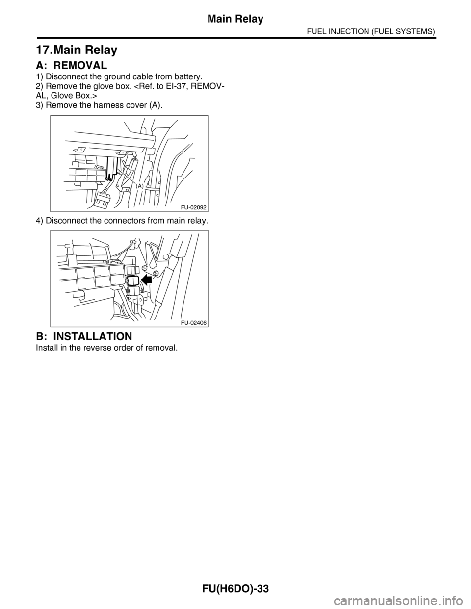
3) Remove the harness cover (A).
4) Disconnect the connectors from main relay.
B: INSTALLATION
Install in the reverse order of removal.
FU-02092
(A)
FU-02406
Page 1595 of 2453
FU(H6DO)-34
Fuel Pump Relay
FUEL INJECTION (FUEL SYSTEMS)
18.Fuel Pump Relay
A: REMOVAL
1) Disconnect the ground cable from battery.
2) Remove the glove box.
AL, Glove Box.>
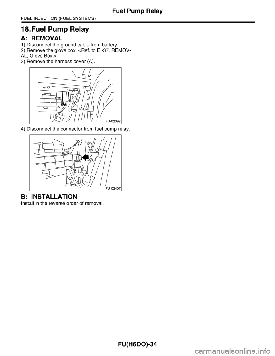
3) Remove the harness cover (A).
4) Disconnect the connector from fuel pump relay.
B: INSTALLATION
Install in the reverse order of removal.
FU-02092
(A)
FU-02407
Page 1596 of 2453
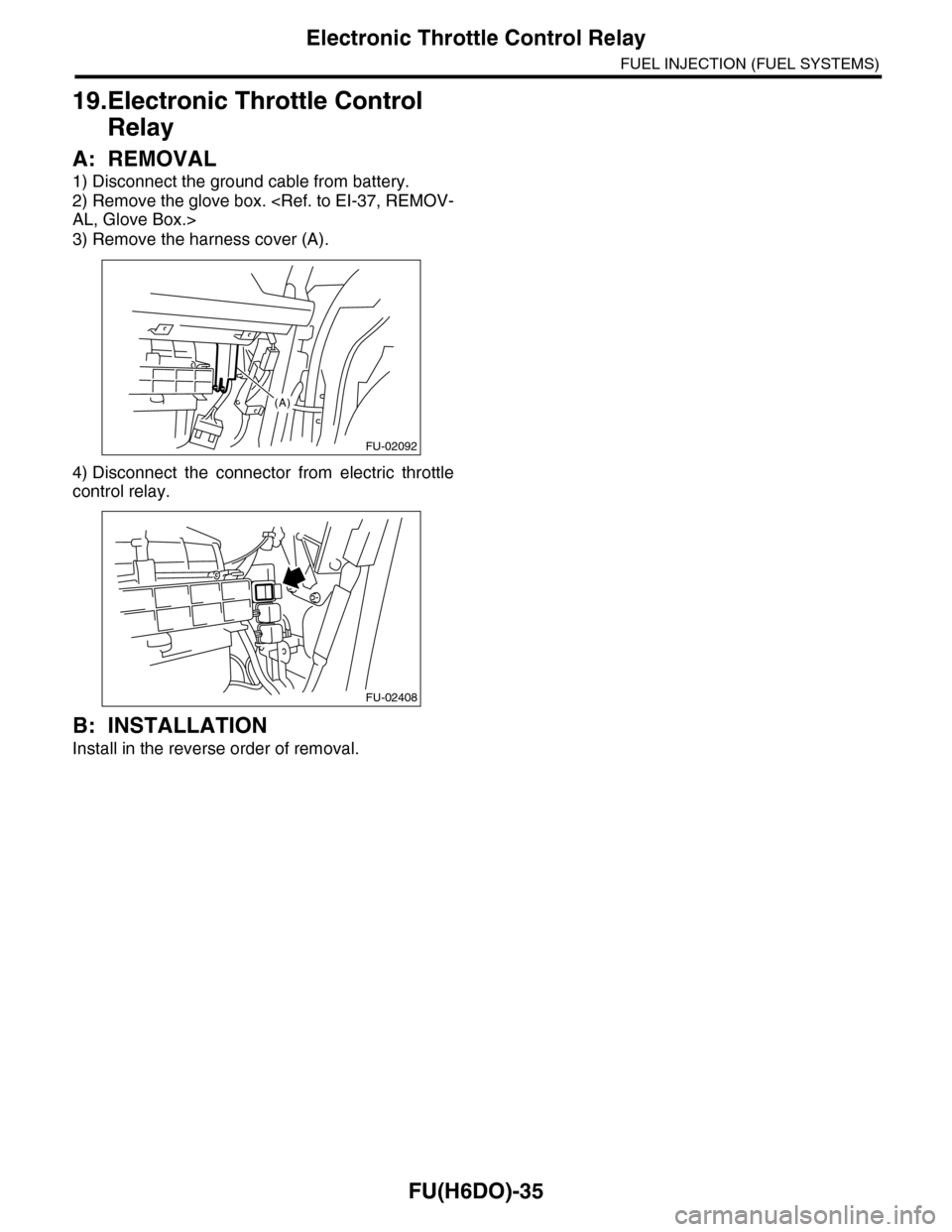
FU(H6DO)-35
Electronic Throttle Control Relay
FUEL INJECTION (FUEL SYSTEMS)
19.Electronic Throttle Control
Relay
A: REMOVAL
1) Disconnect the ground cable from battery.
2) Remove the glove box.
AL, Glove Box.>
3) Remove the harness cover (A).
4) Disconnect the connector from electric throttle
control relay.
B: INSTALLATION
Install in the reverse order of removal.
FU-02092
(A)
FU-02408
Page 1597 of 2453
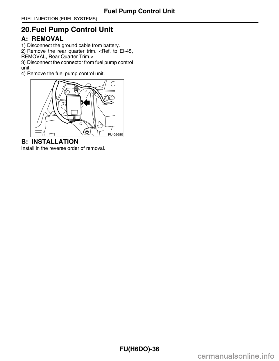
FU(H6DO)-36
Fuel Pump Control Unit
FUEL INJECTION (FUEL SYSTEMS)
20.Fuel Pump Control Unit
A: REMOVAL
1) Disconnect the ground cable from battery.
2) Remove the rear quarter trim.
REMOVAL, Rear Quarter Trim.>
3) Disconnect the connector from fuel pump control
unit.
4) Remove the fuel pump control unit.
B: INSTALLATION
Install in the reverse order of removal.
FU-02680
Page 1598 of 2453
FU(H6DO)-37
Fuel
FUEL INJECTION (FUEL SYSTEMS)
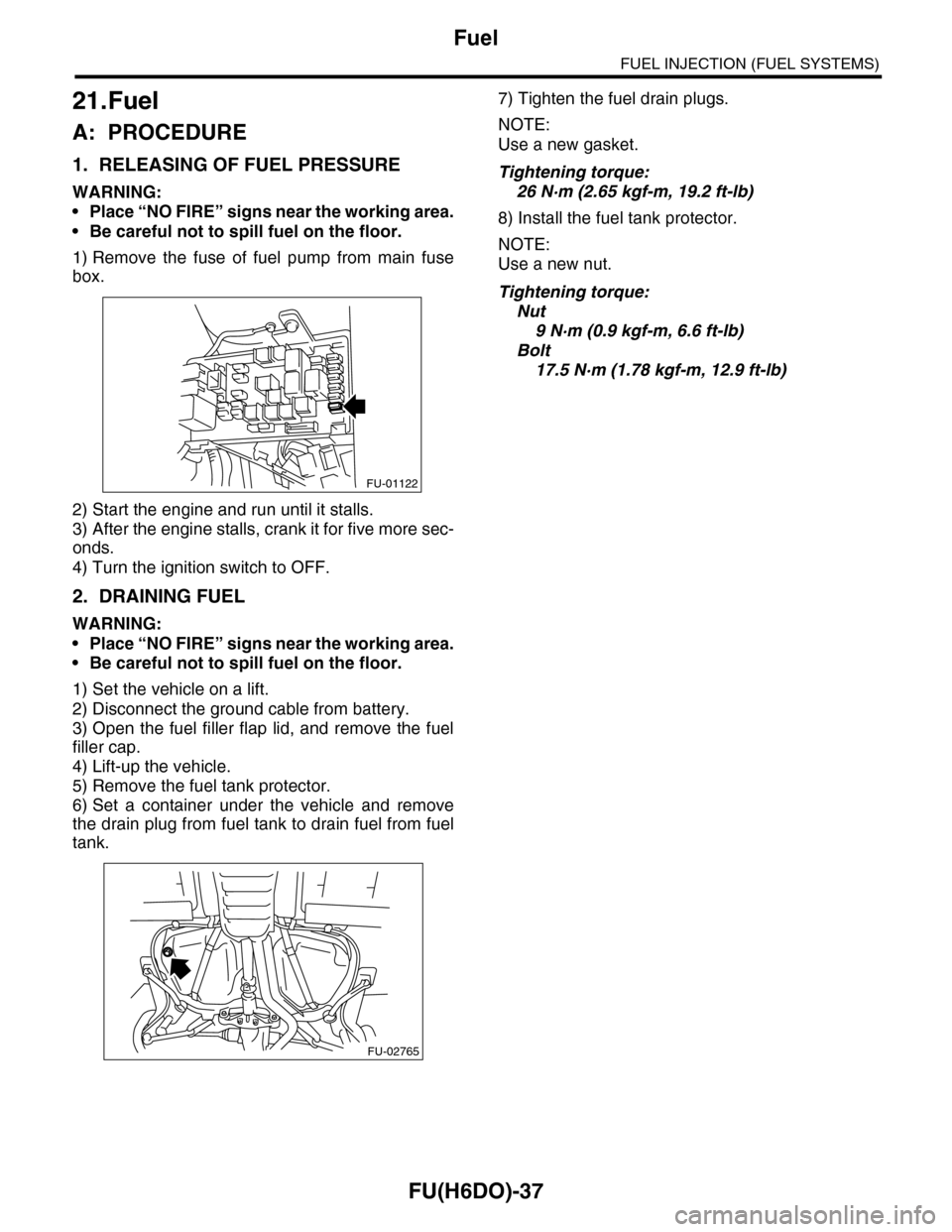
21.Fuel
A: PROCEDURE
1. RELEASING OF FUEL PRESSURE
WARNING:
•Place “NO FIRE” signs near the working area.
•Be careful not to spill fuel on the floor.
1) Remove the fuse of fuel pump from main fuse
box.
2) Start the engine and run until it stalls.
3) After the engine stalls, crank it for five more sec-
onds.
4) Turn the ignition switch to OFF.
2. DRAINING FUEL
WARNING:
•Place “NO FIRE” signs near the working area.
•Be careful not to spill fuel on the floor.
1) Set the vehicle on a lift.
2) Disconnect the ground cable from battery.
3) Open the fuel filler flap lid, and remove the fuel
filler cap.
4) Lift-up the vehicle.
5) Remove the fuel tank protector.
6) Set a container under the vehicle and remove
the drain plug from fuel tank to drain fuel from fuel
tank.
7) Tighten the fuel drain plugs.
NOTE:
Use a new gasket.
Tightening torque:
26 N·m (2.65 kgf-m, 19.2 ft-lb)
8) Install the fuel tank protector.
NOTE:
Use a new nut.
Tightening torque:
Nut
9 N·m (0.9 kgf-m, 6.6 ft-lb)
Bolt
17.5 N·m (1.78 kgf-m, 12.9 ft-lb)
FU-01122
FU-02765
Page 1599 of 2453
FU(H6DO)-38
Fuel Tank
FUEL INJECTION (FUEL SYSTEMS)
22.Fuel Tank
A: REMOVAL
WARNING:
•Place “NO FIRE” signs near the working area.
•Be careful not to spill fuel on the floor.
1) Set the vehicle on a lift.
2) Release the fuel pressure.
37, RELEASING OF FUEL PRESSURE, PROCE-
DURE, Fuel.>
3) Disconnect the ground cable from battery.
4) Drain fuel from fuel tank.
CEDURE, Fuel.>
5) Remove the second seat.
MOVAL, Second-row Seats.>
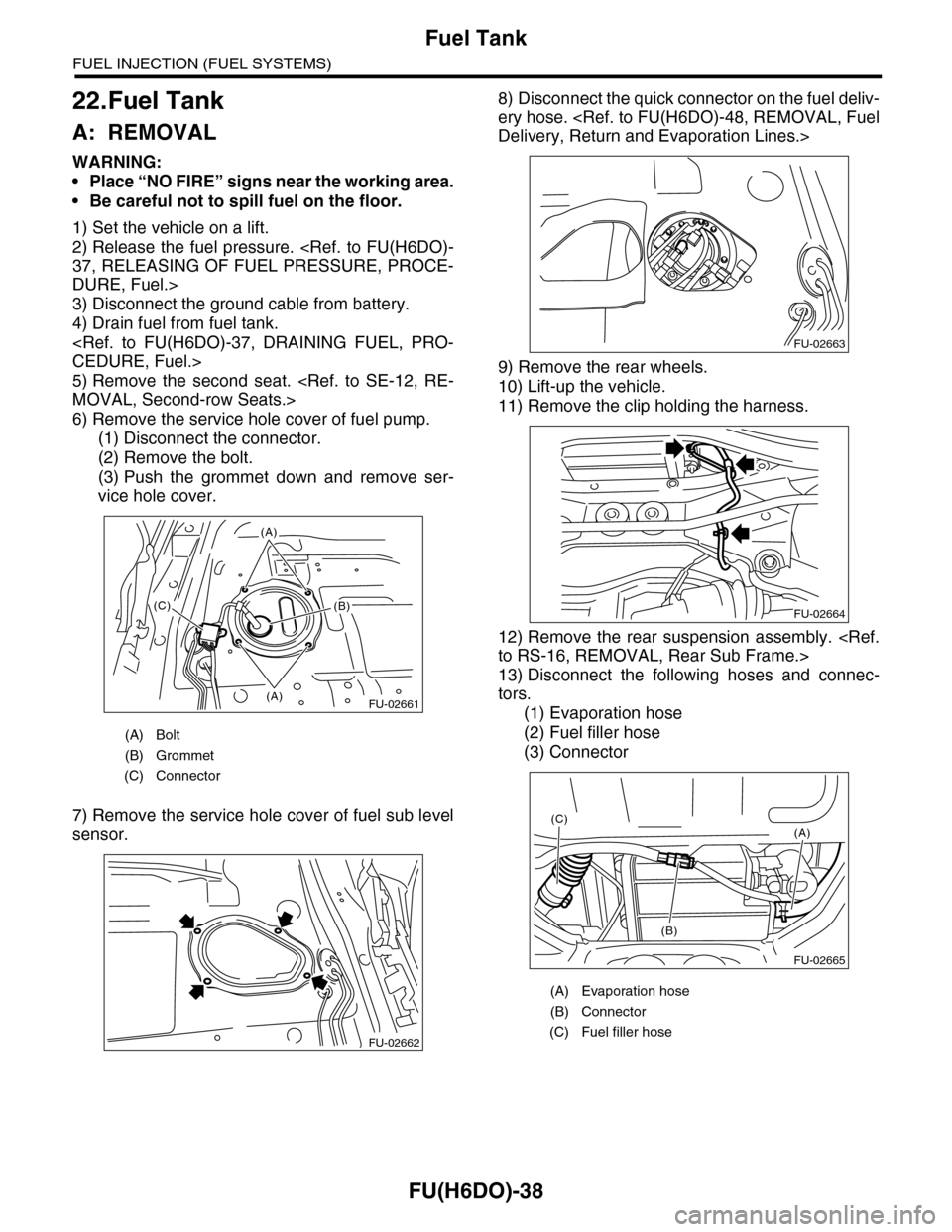
6) Remove the service hole cover of fuel pump.
(1) Disconnect the connector.
(2) Remove the bolt.
(3) Push the grommet down and remove ser-
vice hole cover.
7) Remove the service hole cover of fuel sub level
sensor.
8) Disconnect the quick connector on the fuel deliv-
ery hose.
Delivery, Return and Evaporation Lines.>
9) Remove the rear wheels.
10) Lift-up the vehicle.
11) Remove the clip holding the harness.
12) Remove the rear suspension assembly.
to RS-16, REMOVAL, Rear Sub Frame.>
13) Disconnect the following hoses and connec-
tors.
(1) Evaporation hose
(2) Fuel filler hose
(3) Connector
(A) Bolt
(B) Grommet
(C) Connector
FU-02661(A)
(A)
(B)(C)
FU-02662
(A) Evaporation hose
(B) Connector
(C) Fuel filler hose
FU-02663
FU-02664
FU-02665
(A)
(B)
(C)
Page 1600 of 2453
FU(H6DO)-39
Fuel Tank
FUEL INJECTION (FUEL SYSTEMS)
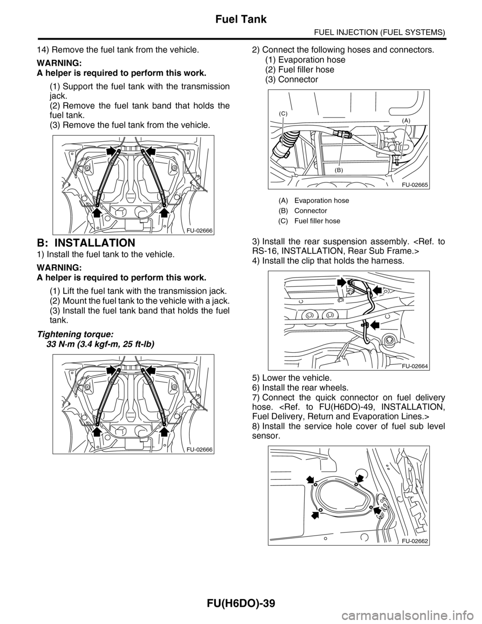
14) Remove the fuel tank from the vehicle.
WARNING:
A helper is required to perform this work.
(1) Support the fuel tank with the transmission
jack.
(2) Remove the fuel tank band that holds the
fuel tank.
(3) Remove the fuel tank from the vehicle.
B: INSTALLATION
1) Install the fuel tank to the vehicle.
WARNING:
A helper is required to perform this work.
(1) Lift the fuel tank with the transmission jack.
(2) Mount the fuel tank to the vehicle with a jack.
(3) Install the fuel tank band that holds the fuel
tank.
Tightening torque:
33 N·m (3.4 kgf-m, 25 ft-lb)
2) Connect the following hoses and connectors.
(1) Evaporation hose
(2) Fuel filler hose
(3) Connector
3) Install the rear suspension assembly.
RS-16, INSTALLATION, Rear Sub Frame.>
4) Install the clip that holds the harness.
5) Lower the vehicle.
6) Install the rear wheels.
7) Connect the quick connector on fuel delivery
hose.
Fuel Delivery, Return and Evaporation Lines.>
8) Install the service hole cover of fuel sub level
sensor.
FU-02666
FU-02666
(A) Evaporation hose
(B) Connector
(C) Fuel filler hose
FU-02665
(A)
(B)
(C)
FU-02664
FU-02662
Trending: tow, jump cable, instrument panel, trunk, catalytic converter, VDC diag, overheating

