SUBARU TRIBECA 2009 1.G Service Workshop Manual
Manufacturer: SUBARU, Model Year: 2009, Model line: TRIBECA, Model: SUBARU TRIBECA 2009 1.GPages: 2453, PDF Size: 46.32 MB
Page 1991 of 2453
PM-8
Engine Oil Filter
PERIODIC MAINTENANCE SERVICES
4. Engine Oil Filter
A: REPLACEMENT
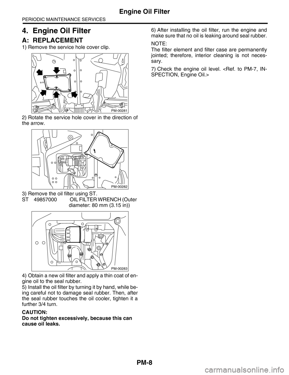
1) Remove the service hole cover clip.
2) Rotate the service hole cover in the direction of
the arrow.
3) Remove the oil filter using ST.
ST 49857000 OIL FILTER WRENCH (Outer
diameter: 80 mm (3.15 in))
4) Obtain a new oil filter and apply a thin coat of en-
gine oil to the seal rubber.
5) Install the oil filter by turning it by hand, while be-
ing careful not to damage seal rubber. Then, after
the seal rubber touches the oil cooler, tighten it a
further 3/4 turn.
CAUTION:
Do not tighten excessively, because this can
cause oil leaks.
6) After installing the oil filter, run the engine and
make sure that no oil is leaking around seal rubber.
NOTE:
The filter element and filter case are permanently
jointed; therefore, interior cleaning is not neces-
sary.
7) Check the engine oil level.
PM-00281
PM-00282
PM-00283
Page 1992 of 2453
PM-9
Spark Plug
PERIODIC MAINTENANCE SERVICES
5. Spark Plug
A: REPLACEMENT
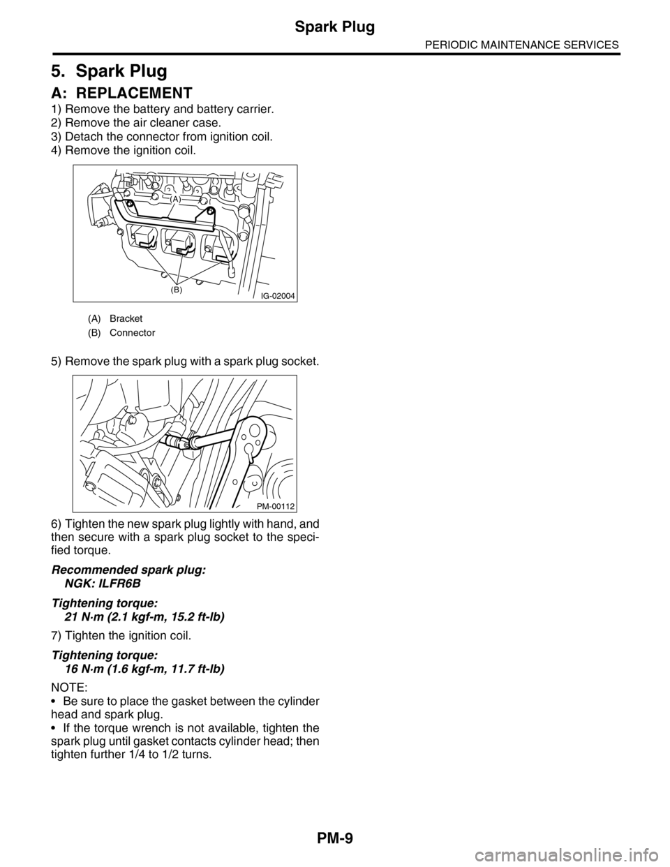
1) Remove the battery and battery carrier.
2) Remove the air cleaner case.
3) Detach the connector from ignition coil.
4) Remove the ignition coil.
5) Remove the spark plug with a spark plug socket.
6) Tighten the new spark plug lightly with hand, and
then secure with a spark plug socket to the speci-
fied torque.
Recommended spark plug:
NGK: ILFR6B
Tightening torque:
21 N·m (2.1 kgf-m, 15.2 ft-lb)
7) Tighten the ignition coil.
Tightening torque:
16 N·m (1.6 kgf-m, 11.7 ft-lb)
NOTE:
•Be sure to place the gasket between the cylinder
head and spark plug.
•If the torque wrench is not available, tighten the
spark plug until gasket contacts cylinder head; then
tighten further 1/4 to 1/2 turns.
(A) Bracket
(B) Connector
IG-02004(B)
(A)
PM-00112
Page 1993 of 2453
PM-10
V-belt
PERIODIC MAINTENANCE SERVICES
6. V-belt
A: INSPECTION
1) Replace the belts if cracks, fraying or wear are
found.
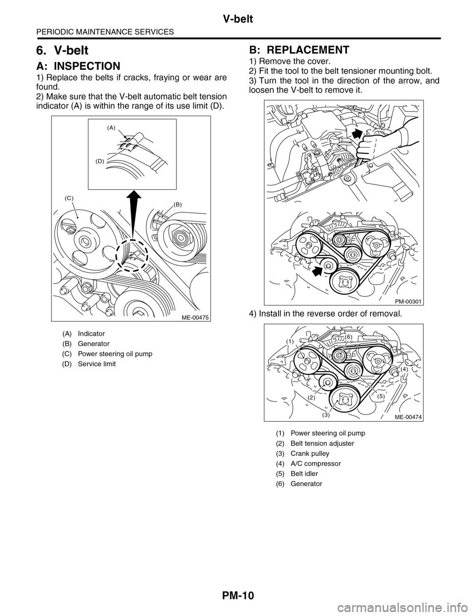
2) Make sure that the V-belt automatic belt tension
indicator (A) is within the range of its use limit (D).
B: REPLACEMENT
1) Remove the cover.
2) Fit the tool to the belt tensioner mounting bolt.
3) Turn the tool in the direction of the arrow, and
loosen the V-belt to remove it.
4) Install in the reverse order of removal.
(A) Indicator
(B) Generator
(C) Power steering oil pump
(D) Service limit
(B)
(A)
(D)
(C)
ME-00475
(1) Power steering oil pump
(2) Belt tension adjuster
(3) Crank pulley
(4) A/C compressor
(5) Belt idler
(6) Generator
PM-00301
(1)(6)
(4)
(5)(2)
(3)ME-00474
Page 1994 of 2453
PM-11
Fuel Line
PERIODIC MAINTENANCE SERVICES
7. Fuel Line
A: INSPECTION
The fuel line is located mostly internally, so check
pipes, areas near pipes, and engine compartment
piping for rust, hose damage, loose band, etc. If
faulty parts are found, repair or replace them.
oration Lines.>
Page 1995 of 2453
PM-12
Air Cleaner Element
PERIODIC MAINTENANCE SERVICES
8. Air Cleaner Element
A: REPLACEMENT
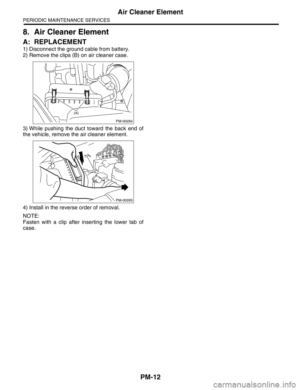
1) Disconnect the ground cable from battery.
2) Remove the clips (B) on air cleaner case.
3) While pushing the duct toward the back end of
the vehicle, remove the air cleaner element.
4) Install in the reverse order of removal.
NOTE:
Fasten with a clip after inserting the lower tab of
case.
PM-00284
(A)
PM-00285
Page 1996 of 2453
PM-13
Cooling System
PERIODIC MAINTENANCE SERVICES
9. Cooling System
A: INSPECTION
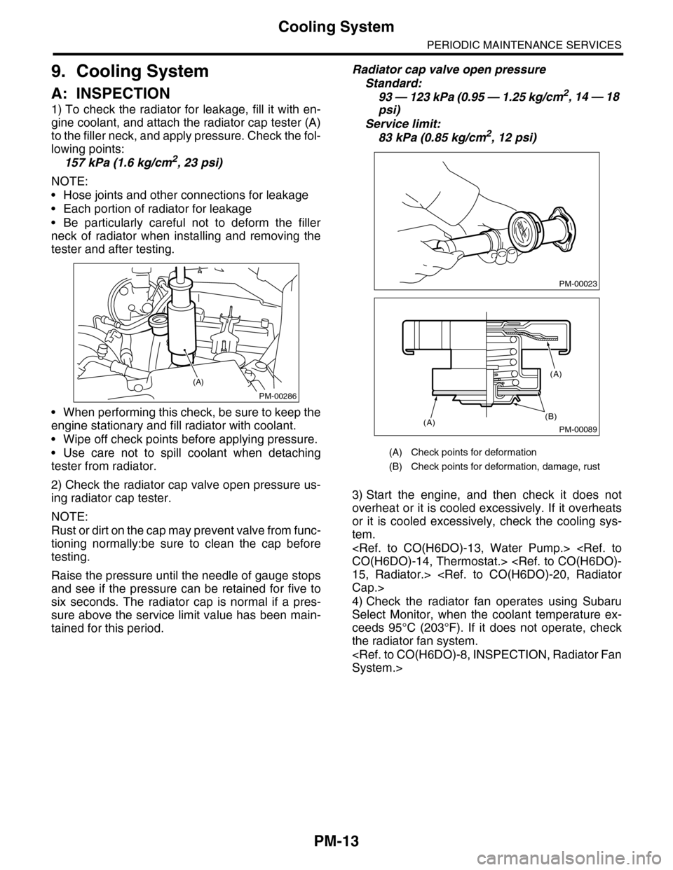
1) To check the radiator for leakage, fill it with en-
gine coolant, and attach the radiator cap tester (A)
to the filler neck, and apply pressure. Check the fol-
lowing points:
157 kPa (1.6 kg/cm2, 23 psi)
NOTE:
•Hose joints and other connections for leakage
•Each portion of radiator for leakage
•Be particularly careful not to deform the filler
neck of radiator when installing and removing the
tester and after testing.
•When performing this check, be sure to keep the
engine stationary and fill radiator with coolant.
•Wipe off check points before applying pressure.
•Use care not to spill coolant when detaching
tester from radiator.
2) Check the radiator cap valve open pressure us-
ing radiator cap tester.
NOTE:
Rust or dirt on the cap may prevent valve from func-
tioning normally:be sure to clean the cap before
testing.
Raise the pressure until the needle of gauge stops
and see if the pressure can be retained for five to
six seconds. The radiator cap is normal if a pres-
sure above the service limit value has been main-
tained for this period.
Radiator cap valve open pressure
Standard:
93 — 123 kPa (0.95 — 1.25 kg/cm2, 14 — 18
psi)
Service limit:
83 kPa (0.85 kg/cm2, 12 psi)
3) Start the engine, and then check it does not
overheat or it is cooled excessively. If it overheats
or it is cooled excessively, check the cooling sys-
tem.
4) Check the radiator fan operates using Subaru
Select Monitor, when the coolant temperature ex-
ceeds 95°C (203°F). If it does not operate, check
the radiator fan system.
PM-00286
(A)
(A) Check points for deformation
(B) Check points for deformation, damage, rust
PM-00023
PM-00089
(B)(A)
(A)
Page 1997 of 2453
PM-14
Engine Coolant
PERIODIC MAINTENANCE SERVICES
10.Engine Coolant
A: REPLACEMENT
1. REPLACEMENT OF ENGINE COOLANT
WARNING:
The radiator is of the pressurized type. Do not
attempt to open the radiator cap immediately
after the engine has been stopped.
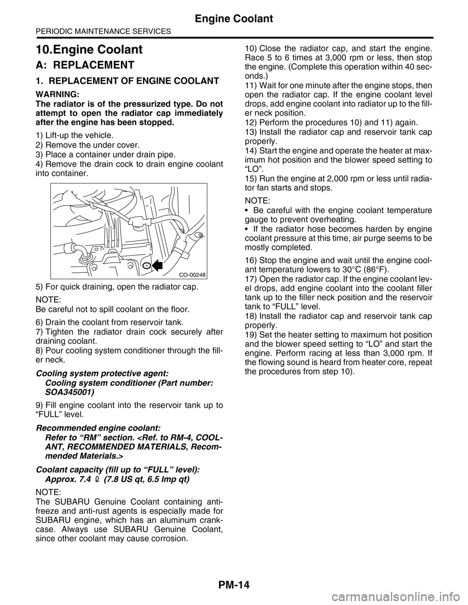
1) Lift-up the vehicle.
2) Remove the under cover.
3) Place a container under drain pipe.
4) Remove the drain cock to drain engine coolant
into container.
5) For quick draining, open the radiator cap.
NOTE:
Be careful not to spill coolant on the floor.
6) Drain the coolant from reservoir tank.
7) Tighten the radiator drain cock securely after
draining coolant.
8) Pour cooling system conditioner through the fill-
er neck.
Cooling system protective agent:
Cooling system conditioner (Part number:
SOA345001)
9) Fill engine coolant into the reservoir tank up to
“FULL” level.
Recommended engine coolant:
Refer to “RM” section.
mended Materials.>
Coolant capacity (fill up to “FULL” level):
Approx. 7.4 2 (7.8 US qt, 6.5 Imp qt)
NOTE:
The SUBARU Genuine Coolant containing anti-
freeze and anti-rust agents is especially made for
SUBARU engine, which has an aluminum crank-
case. Always use SUBARU Genuine Coolant,
since other coolant may cause corrosion.
10) Close the radiator cap, and start the engine.
Race 5 to 6 times at 3,000 rpm or less, then stop
the engine. (Complete this operation within 40 sec-
onds.)
11) Wait for one minute after the engine stops, then
open the radiator cap. If the engine coolant level
drops, add engine coolant into radiator up to the fill-
er neck position.
12) Perform the procedures 10) and 11) again.
13) Install the radiator cap and reservoir tank cap
properly.
14) Start the engine and operate the heater at max-
imum hot position and the blower speed setting to
“LO”.
15) Run the engine at 2,000 rpm or less until radia-
tor fan starts and stops.
NOTE:
•Be careful with the engine coolant temperature
gauge to prevent overheating.
•If the radiator hose becomes harden by engine
coolant pressure at this time, air purge seems to be
mostly completed.
16) Stop the engine and wait until the engine cool-
ant temperature lowers to 30°C (86°F).
17) Open the radiator cap. If the engine coolant lev-
el drops, add engine coolant into the coolant filler
tank up to the filler neck position and the reservoir
tank to “FULL” level.
18) Install the radiator cap and reservoir tank cap
properly.
19) Set the heater setting to maximum hot position
and the blower speed setting to “LO” and start the
engine. Perform racing at less than 3,000 rpm. If
the flowing sound is heard from heater core, repeat
the procedures from step 10).
CO-00248
Page 1998 of 2453
PM-15
Engine Coolant
PERIODIC MAINTENANCE SERVICES
2. RELATIONSHIP OF SUBARU COOLANT
CONCENTRATION AND FREEZING TEM-
PERATURE
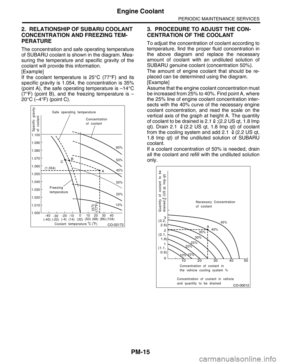
The concentration and safe operating temperature
of SUBARU coolant is shown in the diagram. Mea-
suring the temperature and specific gravity of the
coolant will provide this information.
[Example]
If the coolant temperature is 25°C (77°F) and its
specific gravity is 1.054, the concentration is 35%
(point A), the safe operating temperature is –14°C
(7°F) (point B), and the freezing temperature is –
20°C (–4°F) (point C).
3. PROCEDURE TO ADJUST THE CON-
CENTRATION OF THE COOLANT
To adjust the concentration of coolant according to
temperature, find the proper fluid concentration in
the above diagram and replace the necessary
amount of coolant with an undiluted solution of
SUBARU genuine coolant (concentration 50%).
The amount of engine coolant that should be re-
placed can be determined using the diagram.
[Example]
Assume that the engine coolant concentration must
be increased from 25% to 40%. Find point A, where
the 25% line of engine coolant concentration inter-
sects with the 40% curve of the necessary engine
coolant concentration, and read the scale on the
vertical axis of the graph at height A. The quantity
of coolant to be drained is 2.12;(2.2 US qt, 1.8 Imp
qt). Drain 2.1 2(2.2 US qt, 1.8 Imp qt) of coolant
from the cooling system and add 2.1 2(2.2 US qt,
1.8 Imp qt) of the undiluted solution of SUBARU
coolant.
If a coolant concentration of 50% is needed, drain
all the coolant and refill with the undiluted solution
only.
CO-02172
60%
(1.054)
1.000
1.010
1.020
1.030
1.040
1.050
1.060
1.070
1.080
1.090
1.100
Safe operating temperature
Freezingtemperature
Concentrationof coolant
Specific gravityof coolant
Coolant temperature
B
A
C
-40(-40) (-22)(-4)(14)(32)(50) (68) (86)
( F)
(104)-30-20 -10010203040
(77 F)
50%
40%
30%
20%
25 C
10%
C
CO-00012
100
1
2
3
(1.1, 0.9)
(2.1, 1.8)
(3.2, 2.6)
10%15%
25%20%
30%
35%40%
45%A
20 30 40 50
Concentration of coolant in vehicieand quantity to be drained
Quantity of coolant to bedrained (US qt, Imp qt)
Necessary Concentrationof coolant
Concentration of coolant inthe vehicie cooling system %
Page 1999 of 2453
PM-16
Automatic Transmission Fluid
PERIODIC MAINTENANCE SERVICES
11. Automatic Transmission Fluid
A: INSPECTION
CAUTION:
The level of ATF varies with fluid temperature.
Pay attention to the fluid temperature when
checking ATF level.
1) Raise the ATF temperature by driving a distance
of 5 to 10 km (3 to 6 miles). Otherwise, idle the en-
gine to raise ATF temperature to 70 — 80°C (158
— 176°F) on Subaru Select Monitor.
TION, Subaru Select Monitor.>
2) Make sure the vehicle is level.
3) After selecting all positions (P, R, N, D), shift the
select lever in “P” range. Measure the ATF level
with engine idling for one or two minutes.
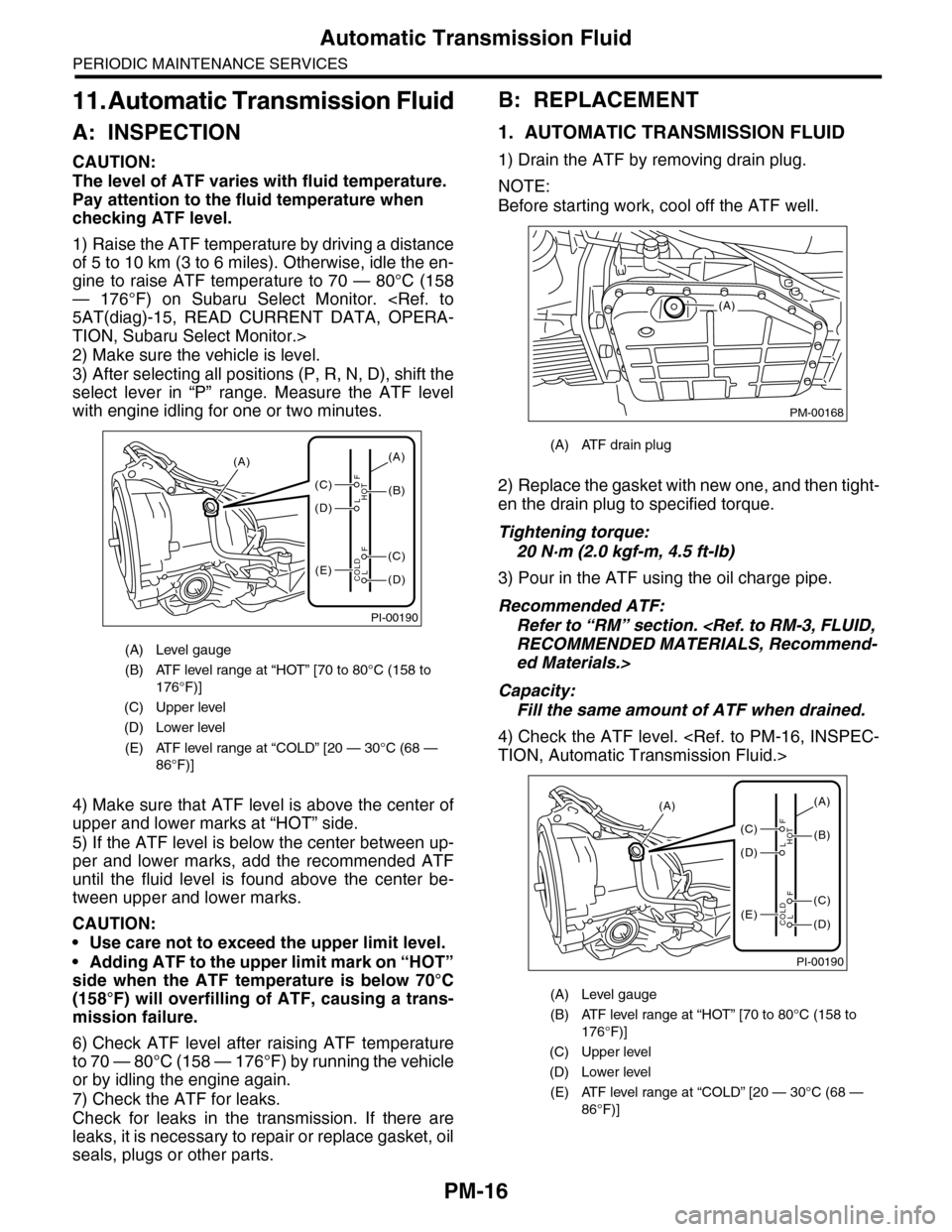
4) Make sure that ATF level is above the center of
upper and lower marks at “HOT” side.
5) If the ATF level is below the center between up-
per and lower marks, add the recommended ATF
until the fluid level is found above the center be-
tween upper and lower marks.
CAUTION:
•Use care not to exceed the upper limit level.
•Adding ATF to the upper limit mark on “HOT”
side when the ATF temperature is below 70°C
(158°F) will overfilling of ATF, causing a trans-
mission failure.
6) Check ATF level after raising ATF temperature
to 70 — 80°C (158 — 176°F) by running the vehicle
or by idling the engine again.
7) Check the ATF for leaks.
Check for leaks in the transmission. If there are
leaks, it is necessary to repair or replace gasket, oil
seals, plugs or other parts.
B: REPLACEMENT
1. AUTOMATIC TRANSMISSION FLUID
1) Drain the ATF by removing drain plug.
NOTE:
Before starting work, cool off the ATF well.
2) Replace the gasket with new one, and then tight-
en the drain plug to specified torque.
Tightening torque:
20 N·m (2.0 kgf-m, 4.5 ft-lb)
3) Pour in the ATF using the oil charge pipe.
Recommended ATF:
Refer to “RM” section.
ed Materials.>
Capacity:
Fill the same amount of ATF when drained.
4) Check the ATF level.
(A) Level gauge
(B) ATF level range at “HOT” [70 to 80°C (158 to
176°F)]
(C) Upper level
(D) Lower level
(E) ATF level range at “COLD” [20 — 30°C (68 —
86°F)]
PI-00190
(A)
(C)
(D)
(E)(D)
(C)
(B)
(A)
F
L
F
HOT
LCOLD
(A) ATF drain plug
(A) Level gauge
(B) ATF level range at “HOT” [70 to 80°C (158 to
176°F)]
(C) Upper level
(D) Lower level
(E) ATF level range at “COLD” [20 — 30°C (68 —
86°F)]
PM-00168
(A)
PI-00190
(A)
(C)
(D)
(E)(D)
(C)
(B)
(A)
F
L
F
HOT
LCOLD
Page 2000 of 2453
PM-17
Automatic Transmission Fluid
PERIODIC MAINTENANCE SERVICES
2. ATF FILTER
NOTE:
Basically, the ATF filter is maintenance free, but
when it is rusted or physically damaged or leaking,
the ATF filter needs to be replaced.
For the replacement procedure of ATF filter, refer
to “ATF FILTER”.