sensor SUBARU TRIBECA 2009 1.G Service Manual PDF
[x] Cancel search | Manufacturer: SUBARU, Model Year: 2009, Model line: TRIBECA, Model: SUBARU TRIBECA 2009 1.GPages: 2453, PDF Size: 46.32 MB
Page 325 of 2453
GW-30
Wiper Deicer System
GLASS/WINDOWS/MIRRORS
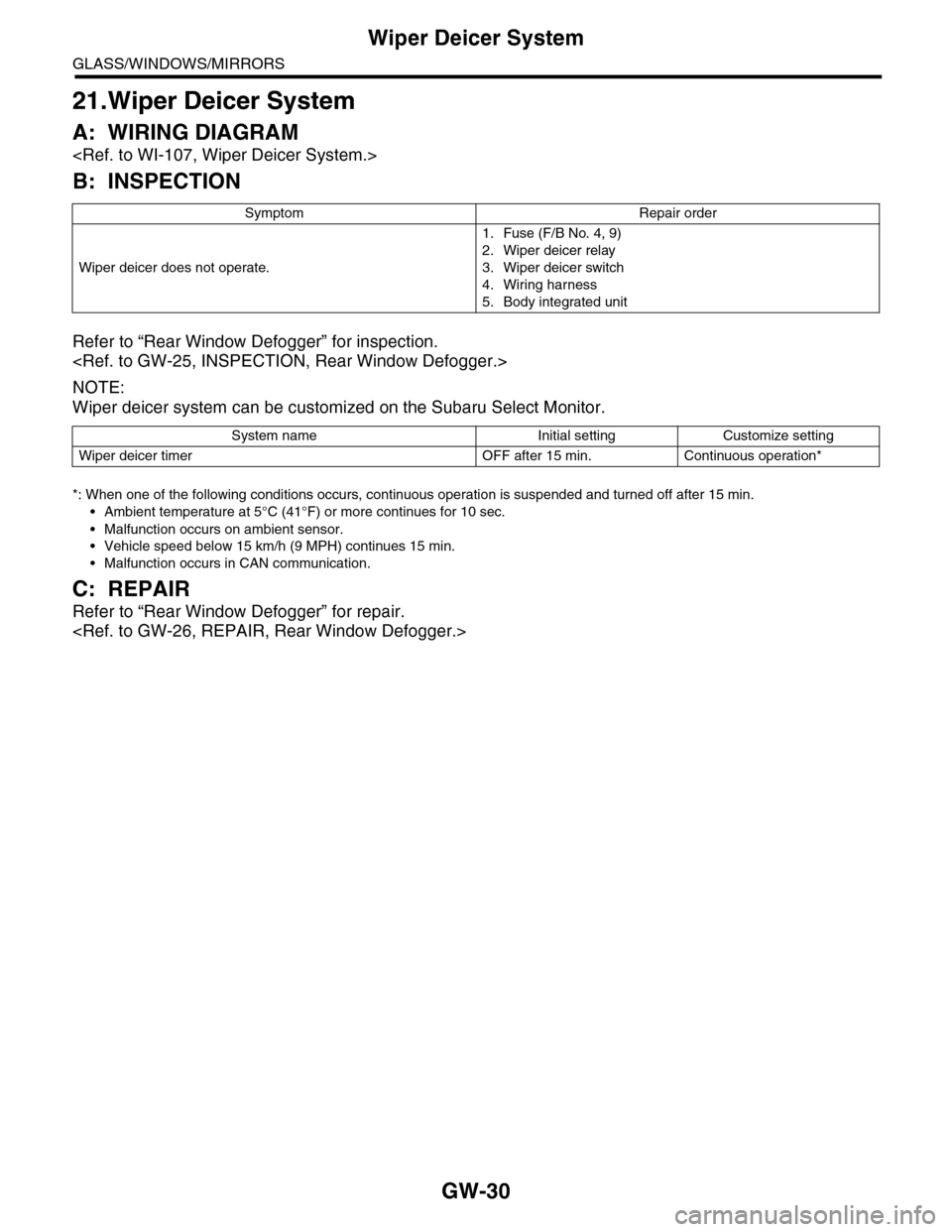
21.Wiper Deicer System
A: WIRING DIAGRAM
B: INSPECTION
Refer to “Rear Window Defogger” for inspection.
NOTE:
Wiper deicer system can be customized on the Subaru Select Monitor.
*: When one of the following conditions occurs, continuous operation is suspended and turned off after 15 min.
•Ambient temperature at 5°C (41°F) or more continues for 10 sec.
•Malfunction occurs on ambient sensor.
•Vehicle speed below 15 km/h (9 MPH) continues 15 min.
•Malfunction occurs in CAN communication.
C: REPAIR
Refer to “Rear Window Defogger” for repair.
Symptom Repair order
Wiper deicer does not operate.
1. Fuse (F/B No. 4, 9)
2. Wiper deicer relay
3. Wiper deicer switch
4. Wiring harness
5. Body integrated unit
System name Initial setting Customize setting
Wiper deicer timer OFF after 15 min. Continuous operation*
Page 333 of 2453
AC-7
General Description
HVAC SYSTEM (HEATER, VENTILATOR AND A/C)
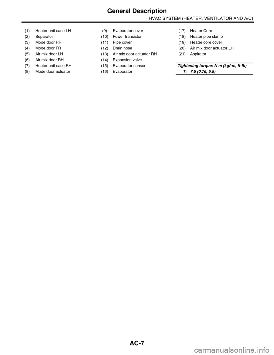
(1) Heater unit case LH (9) Evaporator cover (17) Heater Core
(2) Separator (10) Power transistor (18) Heater pipe clamp
(3) Mode door RR (11) Pipe cover (19) Heater core cover
(4) Mode door FR (12) Drain hose (20) Air mix door actuator LH
(5) Air mix door LH (13) Air mix door actuator RH (21) Aspirator
(6) Air mix door RH (14) Expansion valve
(7) Heater unit case RH (15) Evaporator sensorTightening torque: N·m (kgf-m, ft-lb)
(8) Mode door actuator (16) EvaporatorT: 7.5 (0.76, 5.5)
Page 369 of 2453
AC-43
Ambient Sensor (Auto A/C Model)
HVAC SYSTEM (HEATER, VENTILATOR AND A/C)
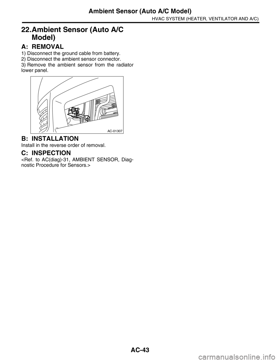
22.Ambient Sensor (Auto A/C
Model)
A: REMOVAL
1) Disconnect the ground cable from battery.
2) Disconnect the ambient sensor connector.
3) Remove the ambient sensor from the radiator
lower panel.
B: INSTALLATION
Install in the reverse order of removal.
C: INSPECTION
AC-01307
Page 370 of 2453
AC-44
Sunload Sensor (Auto A/C Model)
HVAC SYSTEM (HEATER, VENTILATOR AND A/C)
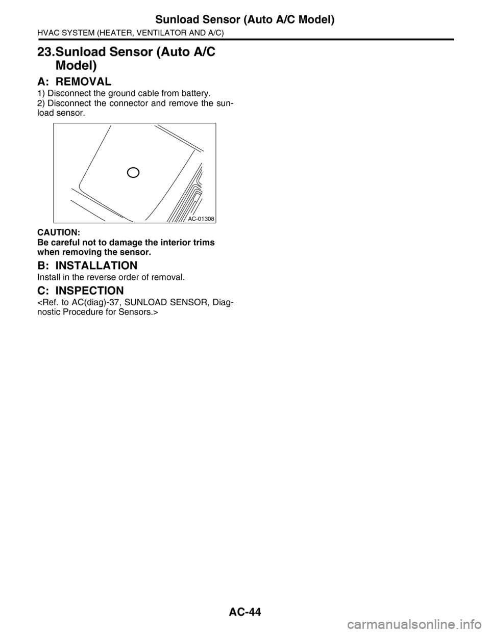
23.Sunload Sensor (Auto A/C
Model)
A: REMOVAL
1) Disconnect the ground cable from battery.
2) Disconnect the connector and remove the sun-
load sensor.
CAUTION:
Be careful not to damage the interior trims
when removing the sensor.
B: INSTALLATION
Install in the reverse order of removal.
C: INSPECTION
AC-01308
Page 371 of 2453
AC-45
In-vehicle Sensor (Auto A/C Model)
HVAC SYSTEM (HEATER, VENTILATOR AND A/C)
24.In-vehicle Sensor (Auto A/C
Model)
A: REMOVAL
1) Disconnect the ground cable from battery.
2) Remove the instrument panel lower panel on
driver’s side.
3) Disconnect the connector and aspirator hose,
remove the catch hook and remove the interior
temperature sensor from the knee guard plate.
CAUTION:
Be careful not to damage the sensors and inte-
rior trim when removing.
B: INSTALLATION
Install in the reverse order of removal.
C: INSPECTION
Page 380 of 2453
AC(diag)-3
General Description
HVAC SYSTEM (AUTO A/C) (DIAGNOSTICS)
2. General Description
A: CAUTION
1) Never connect the battery in reverse polarity.
•Auto A/C control module may be destroyed in-
stantly.
2) Do not disconnect the battery terminals while the
engine is running.
•A large counter electromotive force will be gener-
ated in the generator, and this voltage may damage
electronic parts such as auto A/C control module
etc.
3) Before disconnecting the connectors of each
sensor and the auto A/C control module, be sure to
turn the ignition switch to OFF.
•Auto A/C control module may be damaged.
4) Every A/C-related part is a precision part. Do not
drop them.
5) Airbag system wiring harness is routed near the
A/C control panel and junction box.
CAUTION:
•For airbag system, yellow-colored wiring har-
ness and connectors are all used. Do not use
the electrical test equipment on these circuits.
•Be careful not to damage the airbag system
wiring harness when servicing the A/C control
panel and junction box.
B: INSPECTION
Before performing the diagnosis, check the follow-
ing items which might affect A/C system problems.
1. BATTERY
1) Measure the battery voltage and specific gravity
of electrolyte.
Standard voltage: 12 V
Specific gravity: 1.260 or more
2) Check the condition of the fuses for A/C system
power supply and other fuses.
3) Check the condition of harness and harness
connector connections.
2. ASPIRATOR HOSE
1) Turn the ignition switch to ON, and press the A/
C switch.
2) Turn the temperature control dial to maximum
hot position.
3) Turn the air flow control dial to “DEF” position.
4) Turn the fan speed control dial to 4th position.
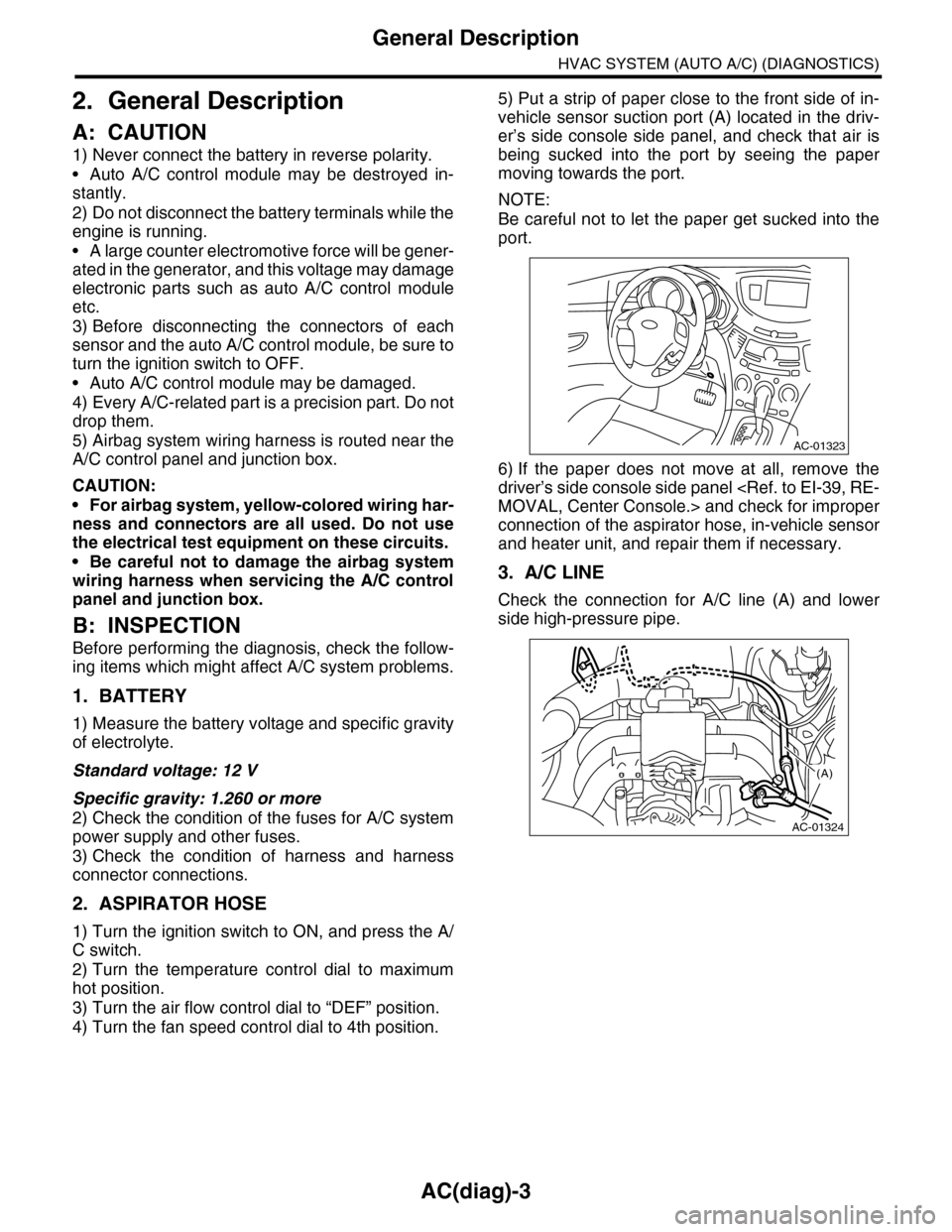
5) Put a strip of paper close to the front side of in-
vehicle sensor suction port (A) located in the driv-
er’s side console side panel, and check that air is
being sucked into the port by seeing the paper
moving towards the port.
NOTE:
Be careful not to let the paper get sucked into the
port.
6) If the paper does not move at all, remove the
driver’s side console side panel
connection of the aspirator hose, in-vehicle sensor
and heater unit, and repair them if necessary.
3. A/C LINE
Check the connection for A/C line (A) and lower
side high-pressure pipe.
AC-01323
AC-01324
(A)
Page 383 of 2453
AC(diag)-6
Electrical Component Location
HVAC SYSTEM (AUTO A/C) (DIAGNOSTICS)
3. Electrical Component Location
A: LOCATION
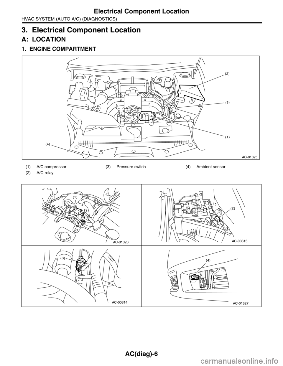
1. ENGINE COMPARTMENT
(1) A/C compressor (3) Pressure switch (4) Ambient sensor
(2) A/C relay
AC-01325
(4)
(2)
(3)
(1)
AC-01326
(1)
AC-00815
(2)
AC-00814
(3)
AC-01327
(4)
Page 384 of 2453
AC(diag)-7
Electrical Component Location
HVAC SYSTEM (AUTO A/C) (DIAGNOSTICS)
2. PASSENGER COMPARTMENT
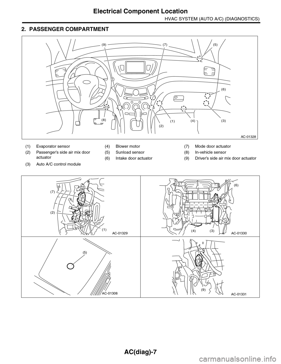
(1) Evaporator sensor (4) Blower motor (7) Mode door actuator
(2) Passenger’s side air mix door
actuator
(5) Sunload sensor (8) In-vehicle sensor
(6) Intake door actuator (9) Driver’s side air mix door actuator
(3) Auto A/C control module
AC-01328
(8)
(2)
(1)(3)(4)
(5)
(6)
(7)(9)
AC-01329
(7)
(2)
(1)AC-01330
(6)
(3)(4)
AC-01308
(5)
AC-01331(9)
Page 385 of 2453
AC(diag)-8
Auto A/C Control Module I/O Signal
HVAC SYSTEM (AUTO A/C) (DIAGNOSTICS)
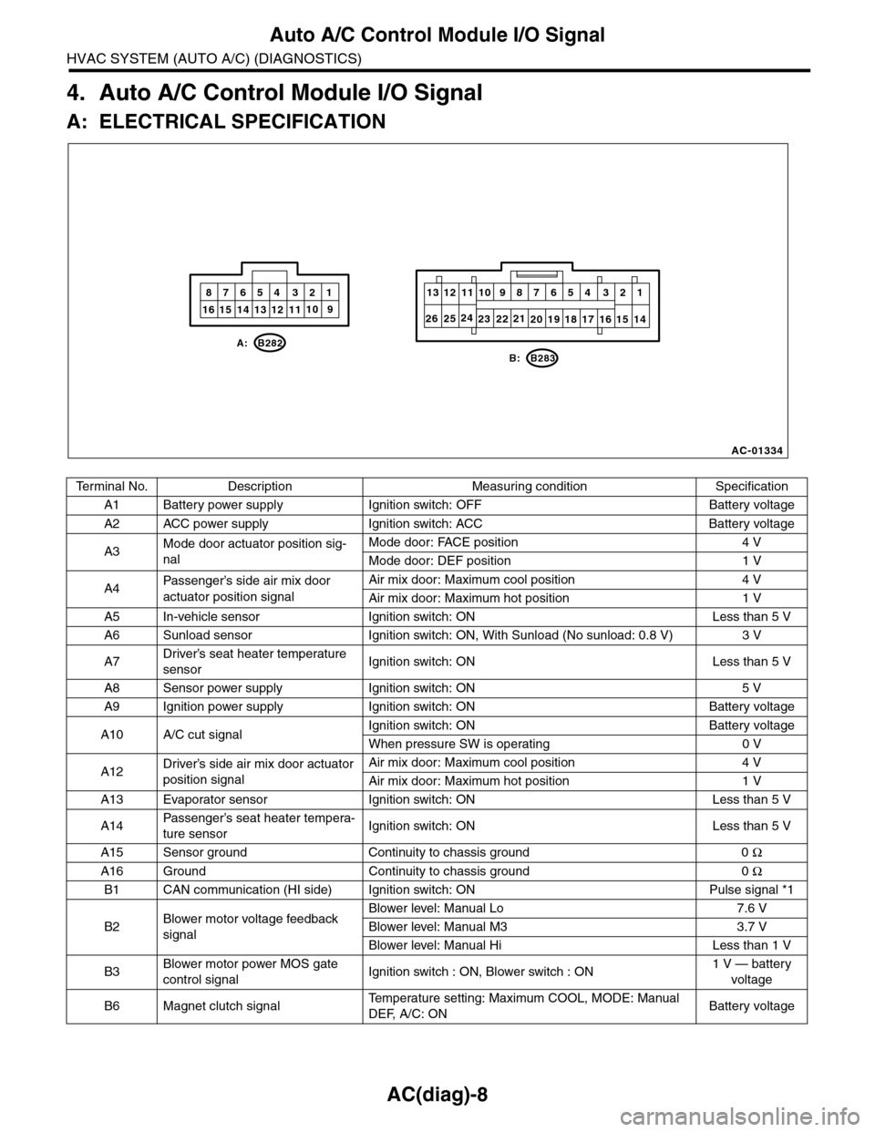
4. Auto A/C Control Module I/O Signal
A: ELECTRICAL SPECIFICATION
Te r m i n a l N o . D e s c r i p t i o n M e a s u r i n g c o n d i t i o n S p e c i f i c a t i o n
A1 Battery power supply Ignition switch: OFF Battery voltage
A2 ACC power supply Ignition switch: ACC Battery voltage
A3Mode door actuator position sig-
nal
Mode door: FACE position 4 V
Mode door: DEF position 1 V
A4Passenger’s side air mix door
actuator position signal
Air mix door: Maximum cool position 4 V
Air mix door: Maximum hot position 1 V
A5 In-vehicle sensor Ignition switch: ON Less than 5 V
A6 Sunload sensor Ignition switch: ON, With Sunload (No sunload: 0.8 V) 3 V
A7Driver’s seat heater temperature
sensorIgnition switch: ON Less than 5 V
A8 Sensor power supply Ignition switch: ON 5 V
A9 Ignition power supply Ignition switch: ON Battery voltage
A10 A/C cut signalIgnition switch: ON Battery voltage
When pressure SW is operating 0 V
A12Driver’s side air mix door actuator
position signal
Air mix door: Maximum cool position 4 V
Air mix door: Maximum hot position 1 V
A13 Evaporator sensor Ignition switch: ON Less than 5 V
A14Passenger’s seat heater tempera-
ture sensorIgnition switch: ON Less than 5 V
A15 Sensor ground Continuity to chassis ground 0 Ω
A16 Ground Continuity to chassis ground 0 Ω
B1 CAN communication (HI side) Ignition switch: ON Pulse signal *1
B2Blower motor voltage feedback
signal
Blower level: Manual Lo 7.6 V
Blower level: Manual M3 3.7 V
Blower level: Manual Hi Less than 1 V
B3Blower motor power MOS gate
control signalIgnition switch : ON, Blower switch : ON1 V — battery
voltage
B6 Magnet clutch signalTe m p e r a t u r e s e t t i n g : M a x i m u m C O O L , M O D E : M a n u a l
DEF, A/C: ONBattery voltage
AC-01334
10
20 19 18 17 16 15 14
13 12 11987654 321
1016 15 14 13 12 119
87654 321
B: B283
A: B282
232122242526
Page 387 of 2453
AC(diag)-10
Diagnostic Chart for Self-diagnosis
HVAC SYSTEM (AUTO A/C) (DIAGNOSTICS)
5. Diagnostic Chart for Self-diagnosis
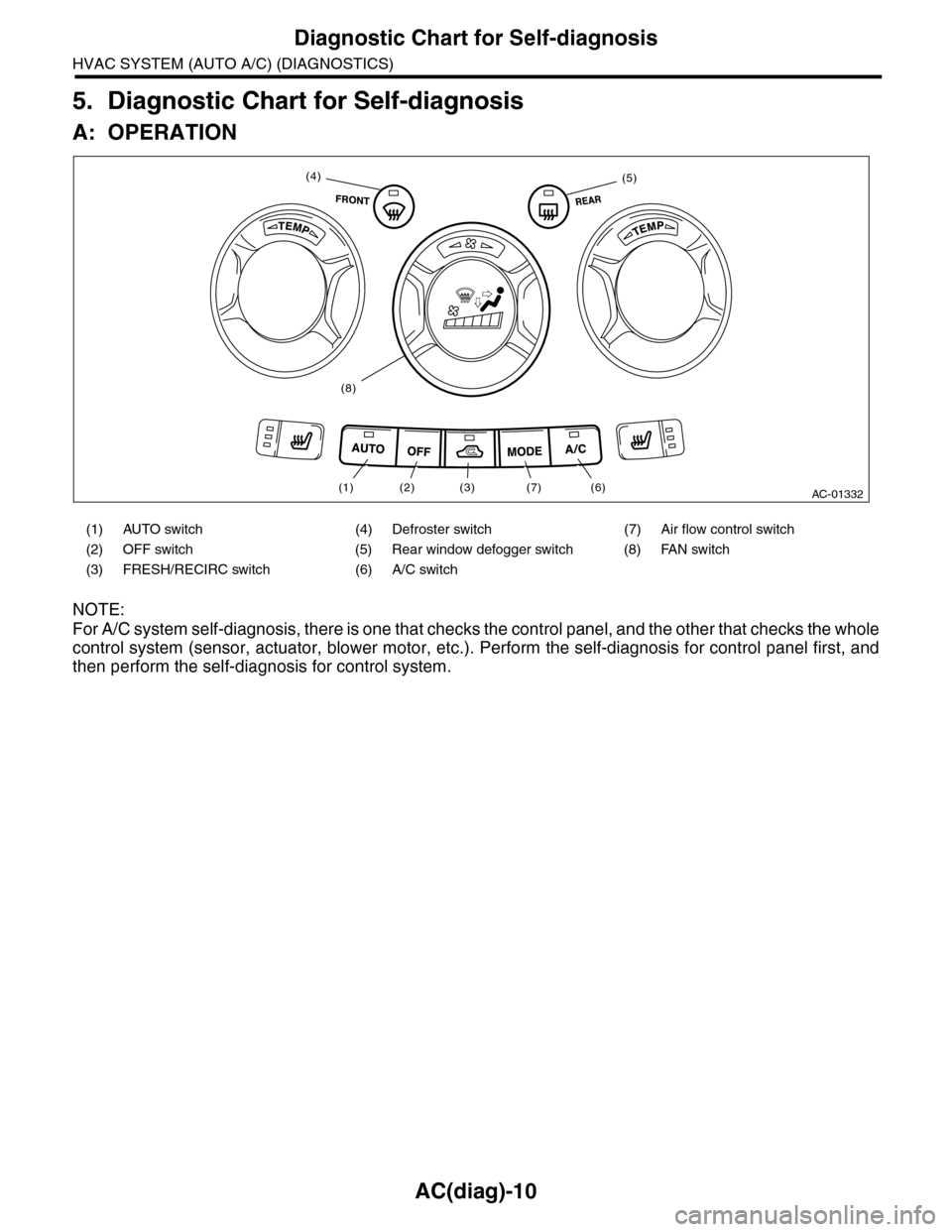
A: OPERATION
NOTE:
For A/C system self-diagnosis, there is one that checks the control panel, and the other that checks the whole
control system (sensor, actuator, blower motor, etc.). Perform the self-diagnosis for control panel first, and
then perform the self-diagnosis for control system.
(1) AUTO switch (4) Defroster switch (7) Air flow control switch
(2) OFF switch (5) Rear window defogger switch (8) FAN switch
(3) FRESH/RECIRC switch (6) A/C switch
AC-01332(6)(7)(3)(2)(1)
(4)(5)
(8)