sensor SUBARU TRIBECA 2009 1.G Service Workshop Manual
[x] Cancel search | Manufacturer: SUBARU, Model Year: 2009, Model line: TRIBECA, Model: SUBARU TRIBECA 2009 1.GPages: 2453, PDF Size: 46.32 MB
Page 511 of 2453
LAN(diag)-55
Diagnostic Procedure with Diagnostic Trouble Code (DTC)
LAN SYSTEM (DIAGNOSTICS)
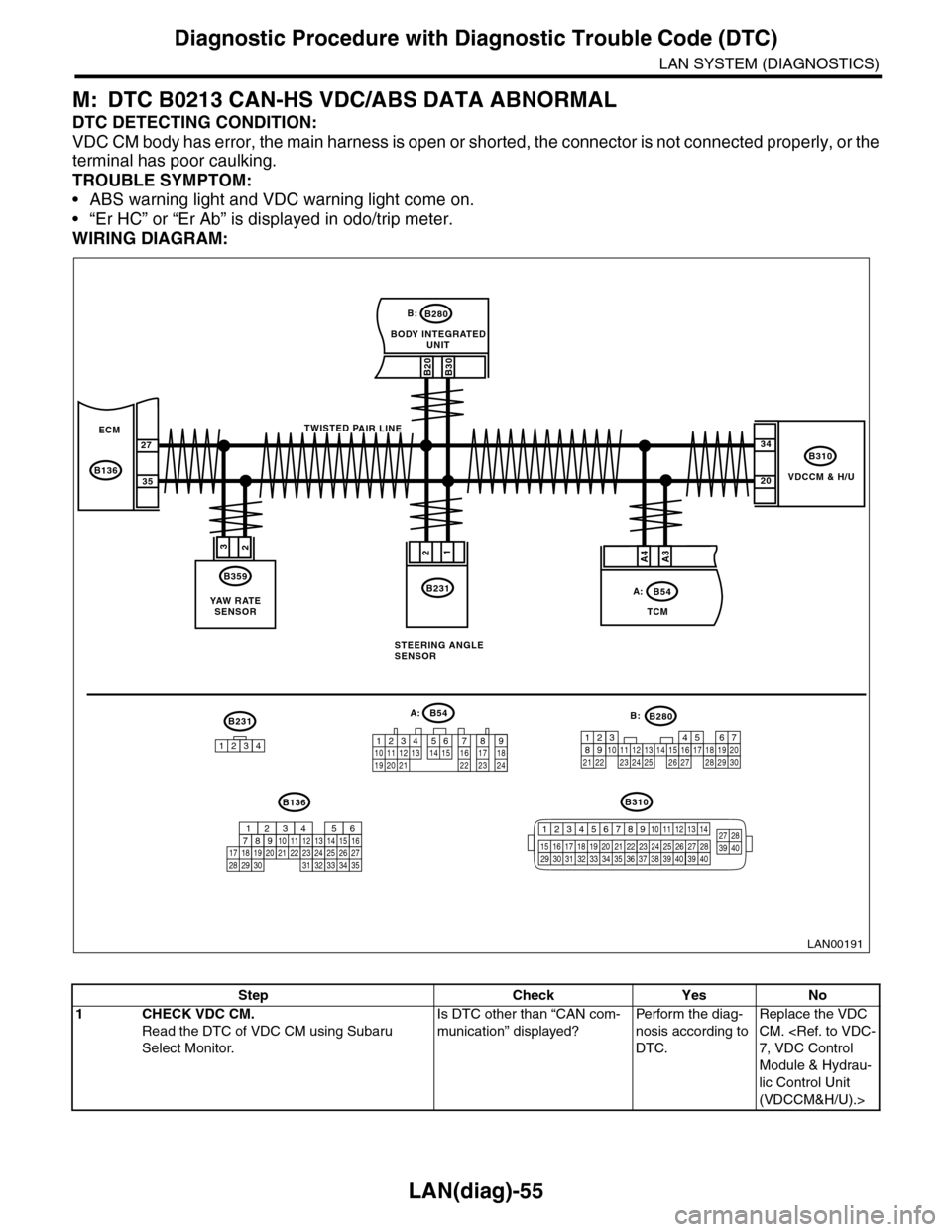
M: DTC B0213 CAN-HS VDC/ABS DATA ABNORMAL
DTC DETECTING CONDITION:
VDC CM body has error, the main harness is open or shorted, the connector is not connected properly, or the
terminal has poor caulking.
TROUBLE SYMPTOM:
•ABS warning light and VDC warning light come on.
•“Er HC” or “Er Ab” is displayed in odo/trip meter.
WIRING DIAGRAM:
VDCCM & H/U
B310
B20B30
BODY INTEGRATEDUNIT
B280B:
TCM
B54A:
23
B359
YAW R AT ESENSOR
34
20
B231
21
STEERING ANGLESENSOR
B231
1234
B54A:
12 7 8 9563410 11 1219 20 2113 14 15 16 17 1822 23 24
B136B310
B280B:
5467821931022 23111213141524 25 26 2716171828 29192021 30
ECM
B136
27
35
A3A4
TWISTED PAIR LINE
12345678910 11 12 13 14
15 16 17 18 19 2021 22 23 24 25 26 27 2829 30 31 32 33 3435 36 37 38 39403940
27 28394016101112131415252430
9871718192028212223293231
123456
2726333435
LAN00191
Step Check Yes No
1CHECK VDC CM.
Read the DTC of VDC CM using Subaru
Select Monitor.
Is DTC other than “CAN com-
munication” displayed?
Pe r for m t h e d ia g -
nosis according to
DTC.
Replace the VDC
CM.
Module & Hydrau-
lic Control Unit
(VDCCM&H/U).>
Page 512 of 2453
LAN(diag)-56
Diagnostic Procedure with Diagnostic Trouble Code (DTC)
LAN SYSTEM (DIAGNOSTICS)
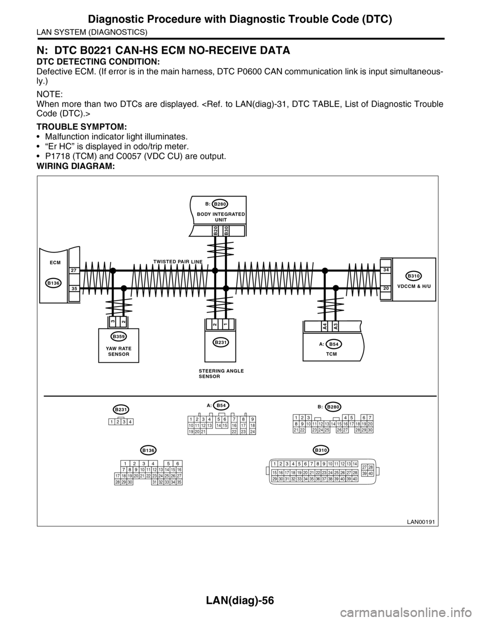
N: DTC B0221 CAN-HS ECM NO-RECEIVE DATA
DTC DETECTING CONDITION:
Defective ECM. (If error is in the main harness, DTC P0600 CAN communication link is input simultaneous-
ly.)
NOTE:
When more than two DTCs are displayed.
TROUBLE SYMPTOM:
•Malfunction indicator light illuminates.
•“Er HC” is displayed in odo/trip meter.
•P1718 (TCM) and C0057 (VDC CU) are output.
WIRING DIAGRAM:
VDCCM & H/U
B310
B20B30
BODY INTEGRATEDUNIT
B280B:
TCM
B54A:
23
B359
YAW R AT ESENSOR
34
20
B231
21
STEERING ANGLESENSOR
B231
1234
B54A:
12 7 8 9563410 11 1219 20 2113 14 15 16 17 1822 23 24
B136B310
B280B:
5467821931022 23111213141524 25 26 2716171828 29192021 30
ECM
B136
27
35
A3A4
TWISTED PAIR LINE
12345678910 11 12 13 14
15 16 17 18 19 2021 22 23 24 25 26 27 2829 30 31 32 33 3435 36 37 38 39403940
27 28394016101112131415252430
9871718192028212223293231
123456
2726333435
LAN00191
Page 515 of 2453
LAN(diag)-59
Diagnostic Procedure with Diagnostic Trouble Code (DTC)
LAN SYSTEM (DIAGNOSTICS)
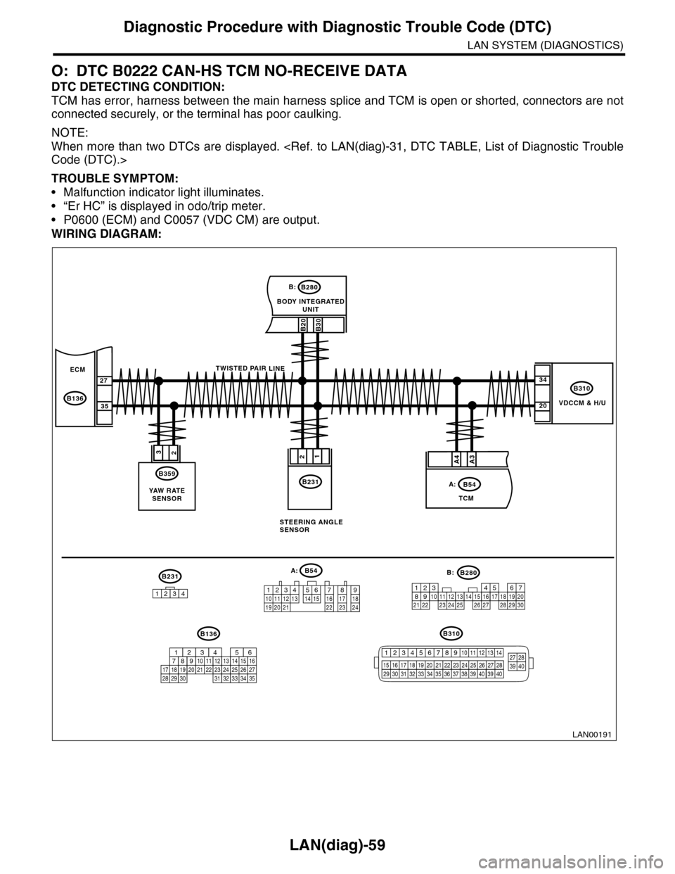
O: DTC B0222 CAN-HS TCM NO-RECEIVE DATA
DTC DETECTING CONDITION:
TCM has error, harness between the main harness splice and TCM is open or shorted, connectors are not
connected securely, or the terminal has poor caulking.
NOTE:
When more than two DTCs are displayed.
TROUBLE SYMPTOM:
•Malfunction indicator light illuminates.
•“Er HC” is displayed in odo/trip meter.
•P0600 (ECM) and C0057 (VDC CM) are output.
WIRING DIAGRAM:
VDCCM & H/U
B310
B20B30
BODY INTEGRATEDUNIT
B280B:
TCM
B54A:
23
B359
YAW R AT ESENSOR
34
20
B231
21
STEERING ANGLESENSOR
B231
1234
B54A:
12 7 8 9563410 11 1219 20 2113 14 15 16 17 1822 23 24
B136B310
B280B:
5467821931022 23111213141524 25 26 2716171828 29192021 30
ECM
B136
27
35
A3A4
TWISTED PAIR LINE
12345678910 11 12 13 14
15 16 17 18 19 2021 22 23 24 25 26 27 2829 30 31 32 33 3435 36 37 38 39403940
27 28394016101112131415252430
9871718192028212223293231
123456
2726333435
LAN00191
Page 517 of 2453
LAN(diag)-61
Diagnostic Procedure with Diagnostic Trouble Code (DTC)
LAN SYSTEM (DIAGNOSTICS)
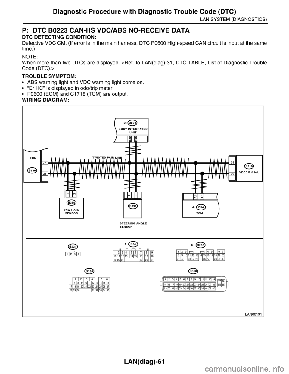
P: DTC B0223 CAN-HS VDC/ABS NO-RECEIVE DATA
DTC DETECTING CONDITION:
Defective VDC CM. (If error is in the main harness, DTC P0600 High-speed CAN circuit is input at the same
time.)
NOTE:
When more than two DTCs are displayed.
TROUBLE SYMPTOM:
•ABS warning light and VDC warning light come on.
•“Er HC” is displayed in odo/trip meter.
•P0600 (ECM) and C1718 (TCM) are output.
WIRING DIAGRAM:
VDCCM & H/U
B310
B20B30
BODY INTEGRATEDUNIT
B280B:
TCM
B54A:
23
B359
YAW R AT ESENSOR
34
20
B231
21
STEERING ANGLESENSOR
B231
1234
B54A:
12 7 8 9563410 11 1219 20 2113 14 15 16 17 1822 23 24
B136B310
B280B:
5467821931022 23111213141524 25 26 2716171828 29192021 30
ECM
B136
27
35
A3A4
TWISTED PAIR LINE
12345678910 11 12 13 14
15 16 17 18 19 2021 22 23 24 25 26 27 2829 30 31 32 33 3435 36 37 38 39403940
27 28394016101112131415252430
9871718192028212223293231
123456
2726333435
LAN00191
Page 532 of 2453
LAN(diag)-76
General Diagnostic Table
LAN SYSTEM (DIAGNOSTICS)
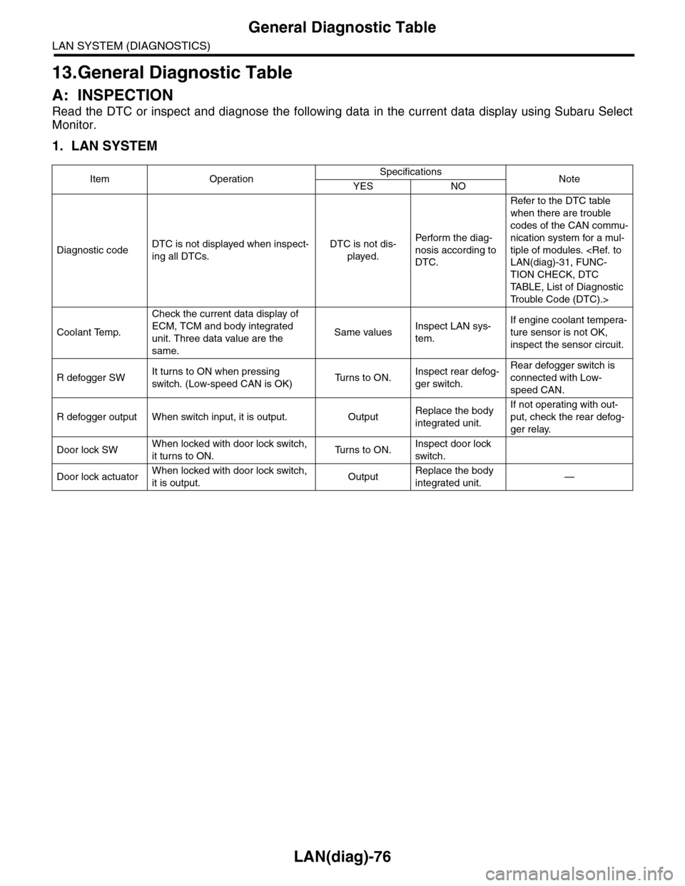
13.General Diagnostic Table
A: INSPECTION
Read the DTC or inspect and diagnose the following data in the current data display using Subaru Select
Monitor.
1. LAN SYSTEM
Item OperationSpecificationsNoteYES NO
Diagnostic codeDTC is not displayed when inspect-
ing all DTCs.
DTC is not dis-
played.
Perfor m the diag-
nosis according to
DTC.
Refer to the DTC table
when there are trouble
codes of the CAN commu-
nication system for a mul-
tiple of modules.
TION CHECK, DTC
TA B L E , L i s t o f D i a g n o s t i c
Tr o u b l e C o d e ( D T C ) . >
Coolant Temp.
Check the current data display of
ECM, TCM and body integrated
unit. Three data value are the
same.
Same valuesInspect LAN sys-
tem.
If engine coolant tempera-
ture sensor is not OK,
inspect the sensor circuit.
R defogger SWIt turns to ON when pressing
switch. (Low-speed CAN is OK)Tu r n s t o O N .Inspect rear defog-
ger switch.
Rear defogger switch is
connected with Low-
speed CAN.
R defogger output When switch input, it is output. OutputReplace the body
integrated unit.
If not operating with out-
put, check the rear defog-
ger relay.
Door lock SWWhen locked with door lock switch,
it turns to ON.Tu r n s t o O N .Inspect door lock
switch.
Door lock actuatorWhen locked with door lock switch,
it is output.OutputReplace the body
integrated unit.—
Page 572 of 2453
OD(diag)-4
General Description
OCCUPANT DETECTION SYSTEM (DIAGNOSTICS)
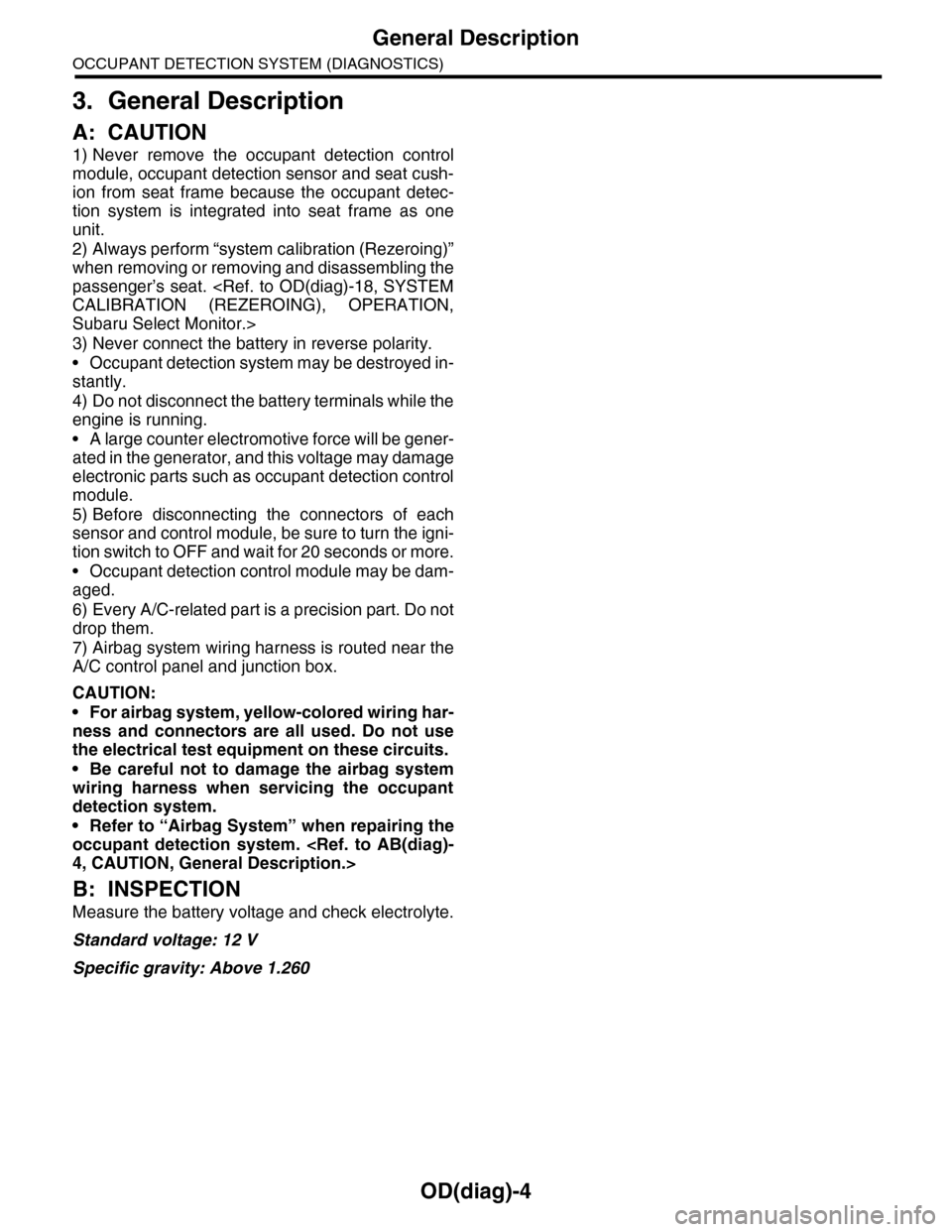
3. General Description
A: CAUTION
1) Never remove the occupant detection control
module, occupant detection sensor and seat cush-
ion from seat frame because the occupant detec-
tion system is integrated into seat frame as one
unit.
2) Always perform “system calibration (Rezeroing)”
when removing or removing and disassembling the
passenger’s seat.
Subaru Select Monitor.>
3) Never connect the battery in reverse polarity.
•Occupant detection system may be destroyed in-
stantly.
4) Do not disconnect the battery terminals while the
engine is running.
•A large counter electromotive force will be gener-
ated in the generator, and this voltage may damage
electronic parts such as occupant detection control
module.
5) Before disconnecting the connectors of each
sensor and control module, be sure to turn the igni-
tion switch to OFF and wait for 20 seconds or more.
•Occupant detection control module may be dam-
aged.
6) Every A/C-related part is a precision part. Do not
drop them.
7) Airbag system wiring harness is routed near the
A/C control panel and junction box.
CAUTION:
•For airbag system, yellow-colored wiring har-
ness and connectors are all used. Do not use
the electrical test equipment on these circuits.
•Be careful not to damage the airbag system
wiring harness when servicing the occupant
detection system.
•Refer to “Airbag System” when repairing the
occupant detection system.
B: INSPECTION
Measure the battery voltage and check electrolyte.
Standard voltage: 12 V
Specific gravity: Above 1.260
Page 580 of 2453
OD(diag)-12
General Description
OCCUPANT DETECTION SYSTEM (DIAGNOSTICS)
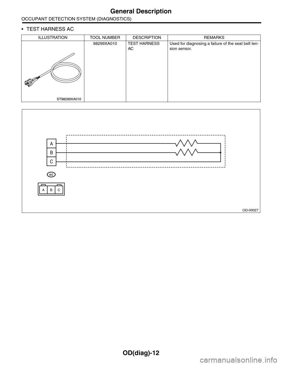
•TEST HARNESS AC
ILLUSTRATION TOOL NUMBER DESCRIPTION REMARKS
98299XA010 TEST HARNESS
AC
Used for diagnosing a failure of the seat belt ten-
sion sensor.
OD-00027
A
B
C
ACB
AC
Page 581 of 2453
OD(diag)-13
General Description
OCCUPANT DETECTION SYSTEM (DIAGNOSTICS)
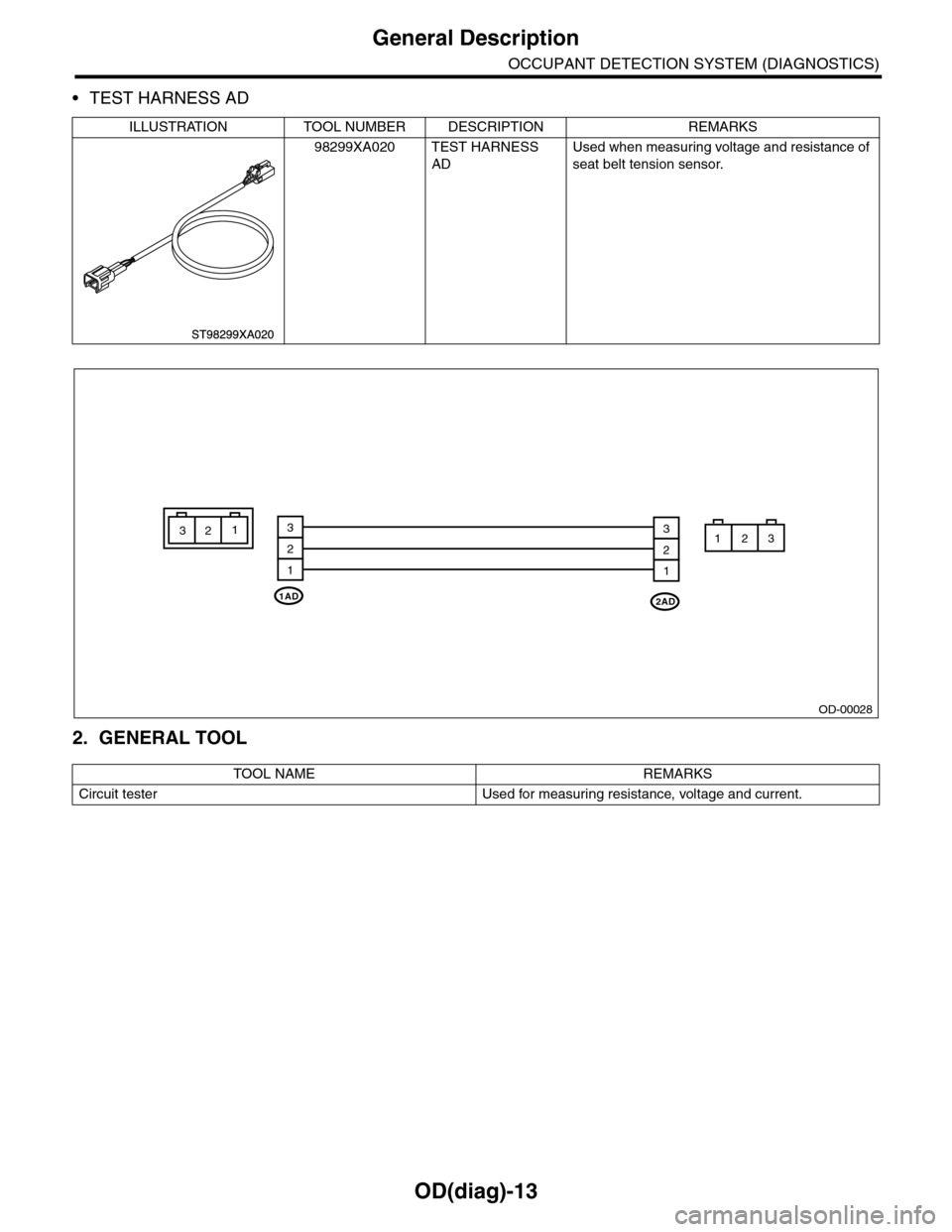
•TEST HARNESS AD
2. GENERAL TOOL
ILLUSTRATION TOOL NUMBER DESCRIPTION REMARKS
98299XA020 TEST HARNESS
AD
Used when measuring voltage and resistance of
seat belt tension sensor.
TOOL NAME REMARKS
Circuit tester Used for measuring resistance, voltage and current.
OD-00028
1AD2AD
3
2
1
3123
2
1
312
Page 582 of 2453
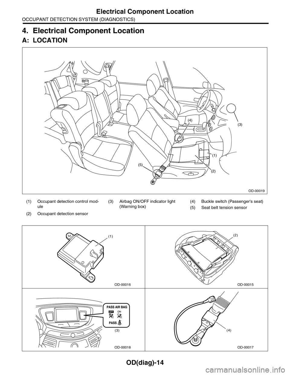
OD(diag)-14
Electrical Component Location
OCCUPANT DETECTION SYSTEM (DIAGNOSTICS)
4. Electrical Component Location
A: LOCATION
(1) Occupant detection control mod-
ule
(3) Airbag ON/OFF indicator light
(Warning box)
(4) Buckle switch (Passenger's seat)
(5) Seat belt tension sensor
(2) Occupant detection sensor
(1)
(2)
(5)
(4)(3)
OD-00019
OD-00016
(1)
OD-00015
(2)
OD-00018
(3)
OD-00017
(4)
Page 584 of 2453
OD(diag)-16
Control Module I/O Signal
OCCUPANT DETECTION SYSTEM (DIAGNOSTICS)
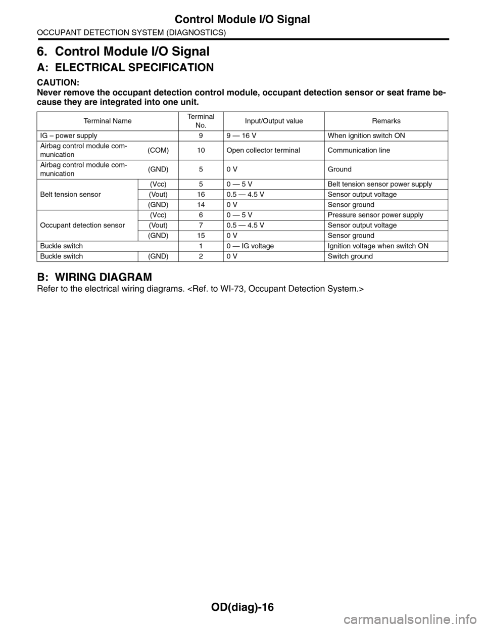
6. Control Module I/O Signal
A: ELECTRICAL SPECIFICATION
CAUTION:
Never remove the occupant detection control module, occupant detection sensor or seat frame be-
cause they are integrated into one unit.
B: WIRING DIAGRAM
Refer to the electrical wiring diagrams.
Te r m i n a l N a m eTe r m i n a l
No.Input/Output value Remarks
IG – power supply 9 9 — 16 V When ignition switch ON
Airbag control module com-
munication(COM) 10 Open collector terminal Communication line
Airbag control module com-
munication(GND) 5 0 V Ground
Belt tension sensor
(Vcc) 5 0 — 5 V Belt tension sensor power supply
(Vout) 16 0.5 — 4.5 V Sensor output voltage
(GND) 14 0 V Sensor ground
Occupant detection sensor
(Vcc) 6 0 — 5 V Pressure sensor power supply
(Vout) 7 0.5 — 4.5 V Sensor output voltage
(GND) 15 0 V Sensor ground
Buckle switch 1 0 — IG voltage Ignition voltage when switch ON
Buckle switch (GND) 2 0 V Switch ground