sensor SUBARU TRIBECA 2009 1.G Service Owners Manual
[x] Cancel search | Manufacturer: SUBARU, Model Year: 2009, Model line: TRIBECA, Model: SUBARU TRIBECA 2009 1.GPages: 2453, PDF Size: 46.32 MB
Page 415 of 2453
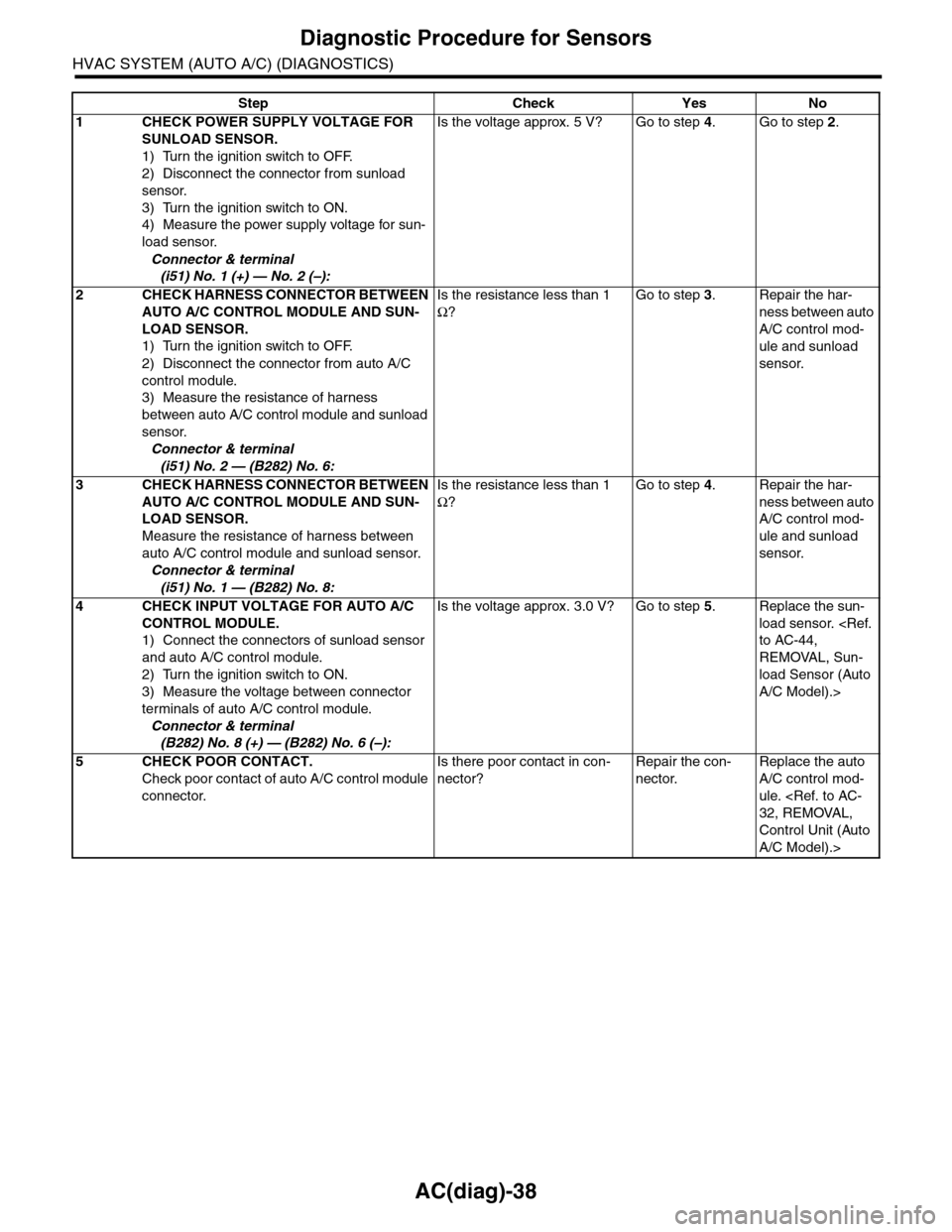
AC(diag)-38
Diagnostic Procedure for Sensors
HVAC SYSTEM (AUTO A/C) (DIAGNOSTICS)
Step Check Yes No
1CHECK POWER SUPPLY VOLTAGE FOR
SUNLOAD SENSOR.
1) Turn the ignition switch to OFF.
2) Disconnect the connector from sunload
sensor.
3) Turn the ignition switch to ON.
4) Measure the power supply voltage for sun-
load sensor.
Connector & terminal
(i51) No. 1 (+) — No. 2 (–):
Is the voltage approx. 5 V? Go to step 4.Go to step 2.
2CHECK HARNESS CONNECTOR BETWEEN
AUTO A/C CONTROL MODULE AND SUN-
LOAD SENSOR.
1) Turn the ignition switch to OFF.
2) Disconnect the connector from auto A/C
control module.
3) Measure the resistance of harness
between auto A/C control module and sunload
sensor.
Connector & terminal
(i51) No. 2 — (B282) No. 6:
Is the resistance less than 1
Ω?
Go to step 3.Repair the har-
ness between auto
A/C control mod-
ule and sunload
sensor.
3CHECK HARNESS CONNECTOR BETWEEN
AUTO A/C CONTROL MODULE AND SUN-
LOAD SENSOR.
Measure the resistance of harness between
auto A/C control module and sunload sensor.
Connector & terminal
(i51) No. 1 — (B282) No. 8:
Is the resistance less than 1
Ω?
Go to step 4.Repair the har-
ness between auto
A/C control mod-
ule and sunload
sensor.
4CHECK INPUT VOLTAGE FOR AUTO A/C
CONTROL MODULE.
1) Connect the connectors of sunload sensor
and auto A/C control module.
2) Turn the ignition switch to ON.
3) Measure the voltage between connector
terminals of auto A/C control module.
Connector & terminal
(B282) No. 8 (+) — (B282) No. 6 (–):
Is the voltage approx. 3.0 V? Go to step 5.Replace the sun-
load sensor.
REMOVAL, Sun-
load Sensor (Auto
A/C Model).>
5CHECK POOR CONTACT.
Check poor contact of auto A/C control module
connector.
Is there poor contact in con-
nector?
Repair the con-
nector.
Replace the auto
A/C control mod-
ule.
Control Unit (Auto
A/C Model).>
Page 416 of 2453
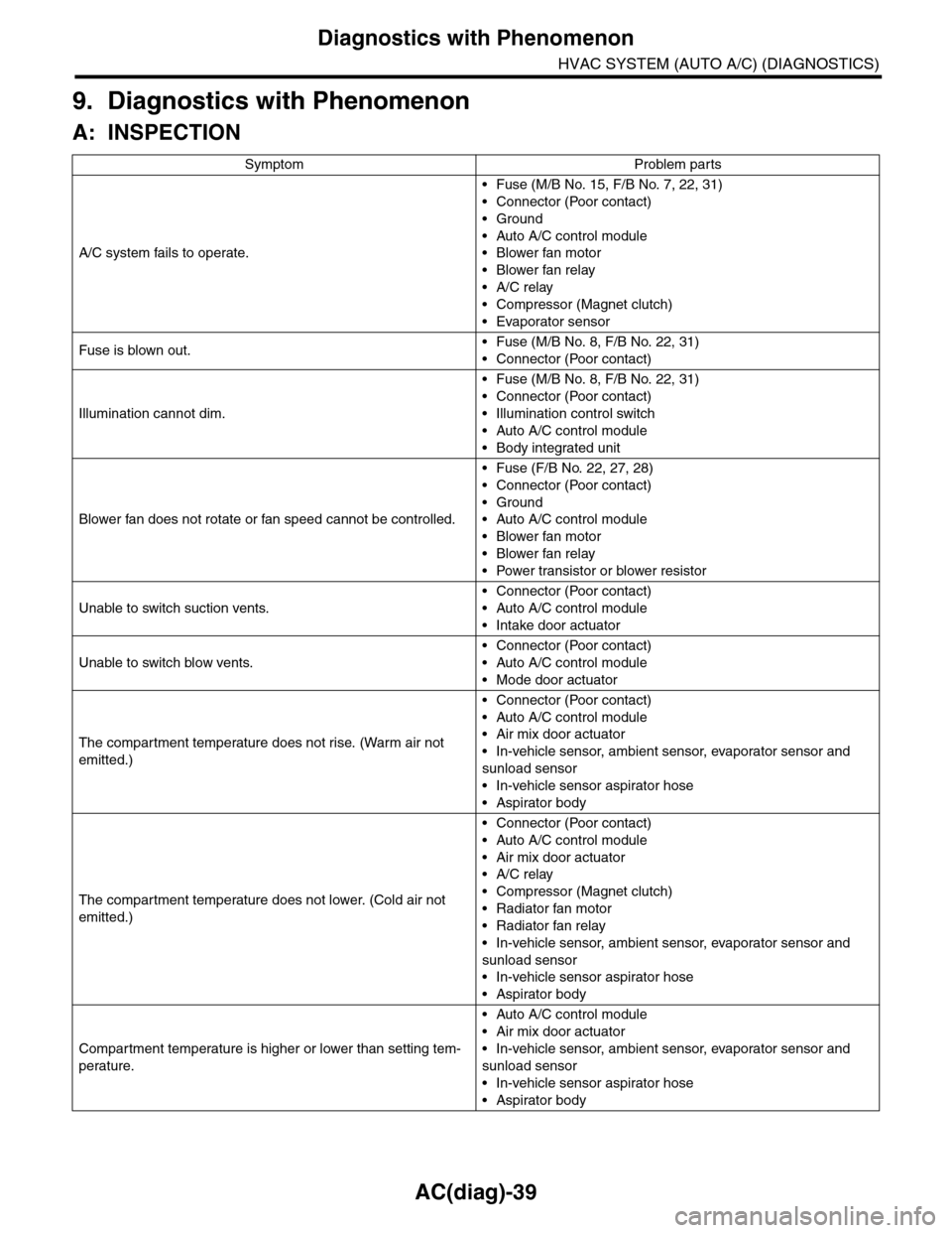
AC(diag)-39
Diagnostics with Phenomenon
HVAC SYSTEM (AUTO A/C) (DIAGNOSTICS)
9. Diagnostics with Phenomenon
A: INSPECTION
Symptom Problem parts
A/C system fails to operate.
•Fuse (M/B No. 15, F/B No. 7, 22, 31)
•Connector (Poor contact)
•Ground
•Auto A/C control module
•Blower fan motor
•Blower fan relay
•A/C relay
•Compressor (Magnet clutch)
•Evaporator sensor
Fuse is blown out.•Fuse (M/B No. 8, F/B No. 22, 31)
•Connector (Poor contact)
Illumination cannot dim.
•Fuse (M/B No. 8, F/B No. 22, 31)
•Connector (Poor contact)
•Illumination control switch
•Auto A/C control module
•Body integrated unit
Blower fan does not rotate or fan speed cannot be controlled.
•Fuse (F/B No. 22, 27, 28)
•Connector (Poor contact)
•Ground
•Auto A/C control module
•Blower fan motor
•Blower fan relay
•Power transistor or blower resistor
Unable to switch suction vents.
•Connector (Poor contact)
•Auto A/C control module
•Intake door actuator
Unable to switch blow vents.
•Connector (Poor contact)
•Auto A/C control module
•Mode door actuator
The compar tment temperature does not rise. (Warm air not
emitted.)
•Connector (Poor contact)
•Auto A/C control module
•Air mix door actuator
•In-vehicle sensor, ambient sensor, evaporator sensor and
sunload sensor
•In-vehicle sensor aspirator hose
•Aspirator body
The compar tment temperature does not lower. (Cold air not
emitted.)
•Connector (Poor contact)
•Auto A/C control module
•Air mix door actuator
•A/C relay
•Compressor (Magnet clutch)
•Radiator fan motor
•Radiator fan relay
•In-vehicle sensor, ambient sensor, evaporator sensor and
sunload sensor
•In-vehicle sensor aspirator hose
•Aspirator body
Compartment temperature is higher or lower than setting tem-
perature.
•Auto A/C control module
•Air mix door actuator
•In-vehicle sensor, ambient sensor, evaporator sensor and
sunload sensor
•In-vehicle sensor aspirator hose
•Aspirator body
Page 417 of 2453
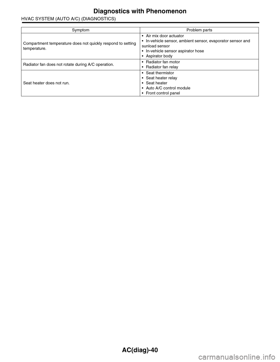
AC(diag)-40
Diagnostics with Phenomenon
HVAC SYSTEM (AUTO A/C) (DIAGNOSTICS)
Compartment temperature does not quickly respond to setting
temperature.
•Air mix door actuator
•In-vehicle sensor, ambient sensor, evaporator sensor and
sunload sensor
•In-vehicle sensor aspirator hose
•Aspirator body
Radiator fan does not rotate during A/C operation.•Radiator fan motor
•Radiator fan relay
Seat heater does not run.
•Seat thermistor
•Seat heater relay
•Seat heater
•Auto A/C control module
•Front control panel
Symptom Problem parts
Page 446 of 2453
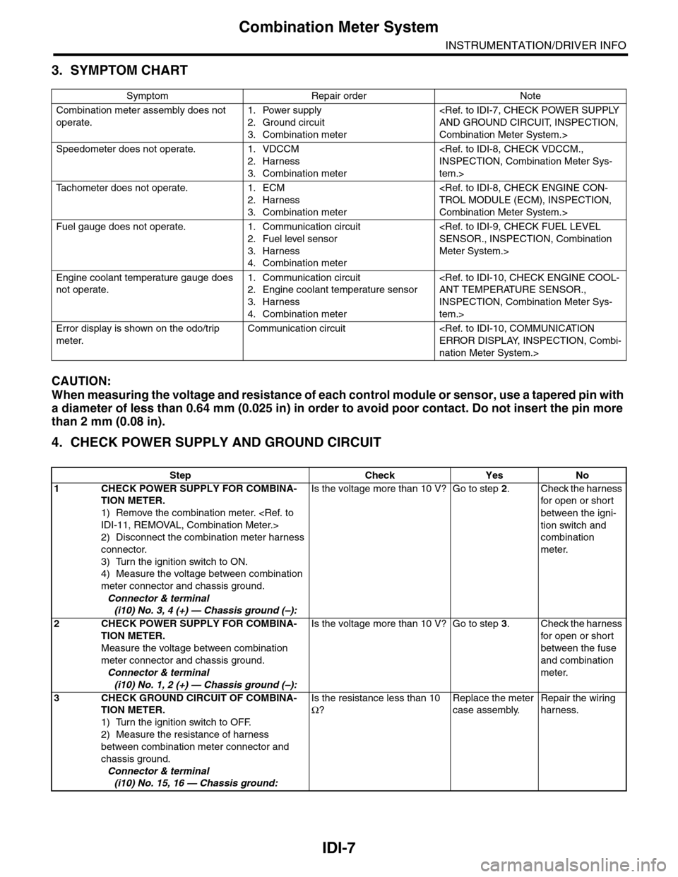
IDI-7
Combination Meter System
INSTRUMENTATION/DRIVER INFO
3. SYMPTOM CHART
CAUTION:
When measuring the voltage and resistance of each control module or sensor, use a tapered pin with
a diameter of less than 0.64 mm (0.025 in) in order to avoid poor contact. Do not insert the pin more
than 2 mm (0.08 in).
4. CHECK POWER SUPPLY AND GROUND CIRCUIT
Symptom Repair order Note
Combination meter assembly does not
operate.
1. Power supply
2. Ground circuit
3. Combination meter
Combination Meter System.>
Speedometer does not operate. 1. VDCCM
2. Harness
3. Combination meter
tem.>
Ta c h o m e t e r d o e s n o t o p e r a t e . 1 . E C M
2. Harness
3. Combination meter
Combination Meter System.>
Fuel gauge does not operate. 1. Communication circuit
2. Fuel level sensor
3. Harness
4. Combination meter
Meter System.>
Engine coolant temperature gauge does
not operate.
1. Communication circuit
2. Engine coolant temperature sensor
3. Harness
4. Combination meter
INSPECTION, Combination Meter Sys-
tem.>
Error display is shown on the odo/trip
meter.
Communication circuit
nation Meter System.>
Step Check Yes No
1CHECK POWER SUPPLY FOR COMBINA-
TION METER.
1) Remove the combination meter.
2) Disconnect the combination meter harness
connector.
3) Turn the ignition switch to ON.
4) Measure the voltage between combination
meter connector and chassis ground.
Connector & terminal
(i10) No. 3, 4 (+) — Chassis ground (–):
Is the voltage more than 10 V? Go to step 2.Check the harness
for open or shor t
between the igni-
tion switch and
combination
meter.
2CHECK POWER SUPPLY FOR COMBINA-
TION METER.
Measure the voltage between combination
meter connector and chassis ground.
Connector & terminal
(i10) No. 1, 2 (+) — Chassis ground (–):
Is the voltage more than 10 V? Go to step 3.Check the harness
for open or shor t
between the fuse
and combination
meter.
3CHECK GROUND CIRCUIT OF COMBINA-
TION METER.
1) Turn the ignition switch to OFF.
2) Measure the resistance of harness
between combination meter connector and
chassis ground.
Connector & terminal
(i10) No. 15, 16 — Chassis ground:
Is the resistance less than 10
Ω?
Replace the meter
case assembly.
Repair the wiring
harness.
Page 448 of 2453
IDI-9
Combination Meter System
INSTRUMENTATION/DRIVER INFO
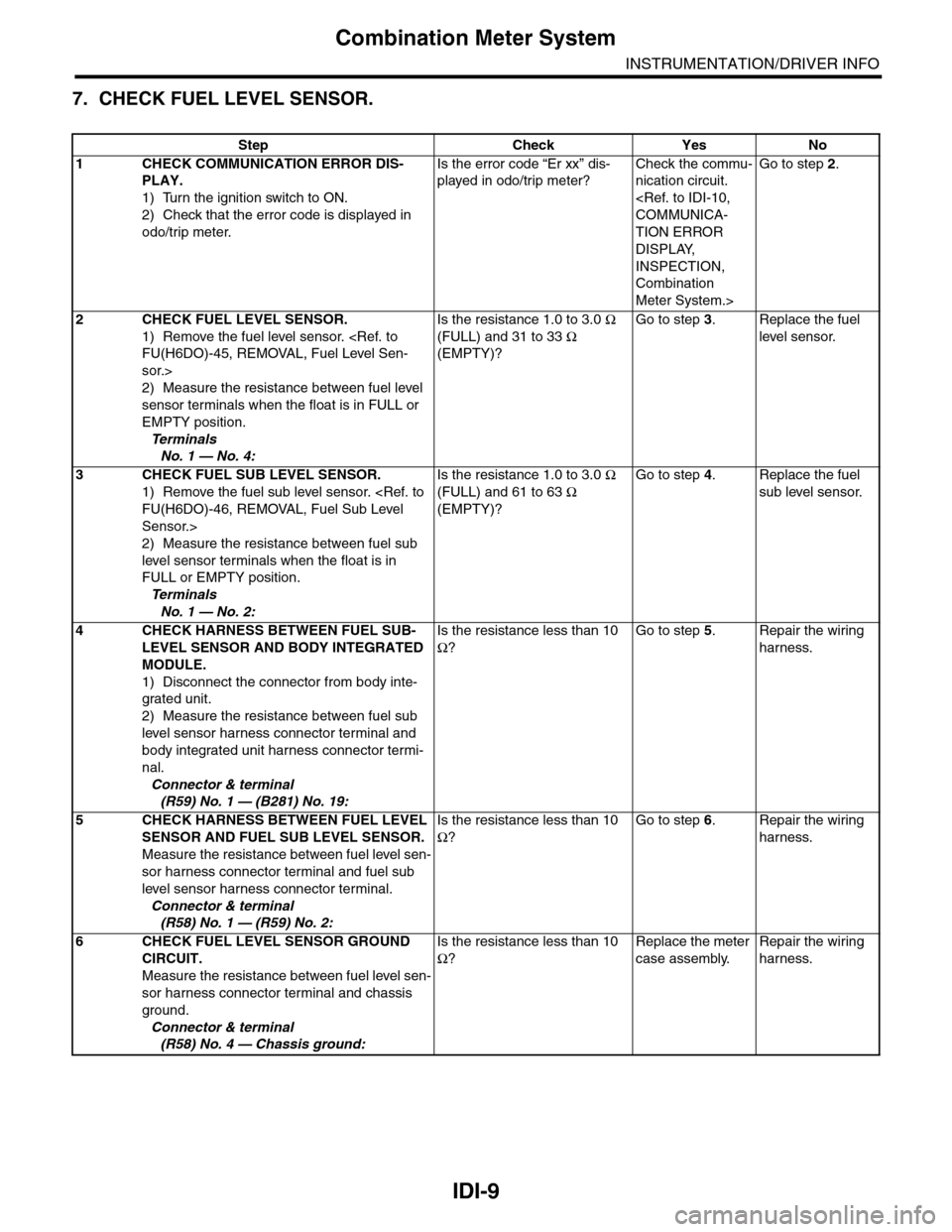
7. CHECK FUEL LEVEL SENSOR.
Step Check Yes No
1CHECK COMMUNICATION ERROR DIS-
PLAY.
1) Turn the ignition switch to ON.
2) Check that the error code is displayed in
odo/trip meter.
Is the error code “Er xx” dis-
played in odo/trip meter?
Check the commu-
nication circuit.
TION ERROR
DISPLAY,
INSPECTION,
Combination
Meter System.>
Go to step 2.
2CHECK FUEL LEVEL SENSOR.
1) Remove the fuel level sensor.
sor.>
2) Measure the resistance between fuel level
sensor terminals when the float is in FULL or
EMPTY position.
Te r m i n a l s
No. 1 — No. 4:
Is the resistance 1.0 to 3.0 Ω
(FULL) and 31 to 33 Ω
(EMPTY)?
Go to step 3.Replace the fuel
level sensor.
3CHECK FUEL SUB LEVEL SENSOR.
1) Remove the fuel sub level sensor.
Sensor.>
2) Measure the resistance between fuel sub
level sensor terminals when the float is in
FULL or EMPTY position.
Te r m i n a l s
No. 1 — No. 2:
Is the resistance 1.0 to 3.0 Ω
(FULL) and 61 to 63 Ω
(EMPTY)?
Go to step 4.Replace the fuel
sub level sensor.
4CHECK HARNESS BETWEEN FUEL SUB-
LEVEL SENSOR AND BODY INTEGRATED
MODULE.
1) Disconnect the connector from body inte-
grated unit.
2) Measure the resistance between fuel sub
level sensor harness connector terminal and
body integrated unit harness connector termi-
nal.
Connector & terminal
(R59) No. 1 — (B281) No. 19:
Is the resistance less than 10
Ω?
Go to step 5.Repair the wiring
harness.
5CHECK HARNESS BETWEEN FUEL LEVEL
SENSOR AND FUEL SUB LEVEL SENSOR.
Measure the resistance between fuel level sen-
sor harness connector terminal and fuel sub
level sensor harness connector terminal.
Connector & terminal
(R58) No. 1 — (R59) No. 2:
Is the resistance less than 10
Ω?
Go to step 6.Repair the wiring
harness.
6CHECK FUEL LEVEL SENSOR GROUND
CIRCUIT.
Measure the resistance between fuel level sen-
sor harness connector terminal and chassis
ground.
Connector & terminal
(R58) No. 4 — Chassis ground:
Is the resistance less than 10
Ω?
Replace the meter
case assembly.
Repair the wiring
harness.
Page 449 of 2453
IDI-10
Combination Meter System
INSTRUMENTATION/DRIVER INFO
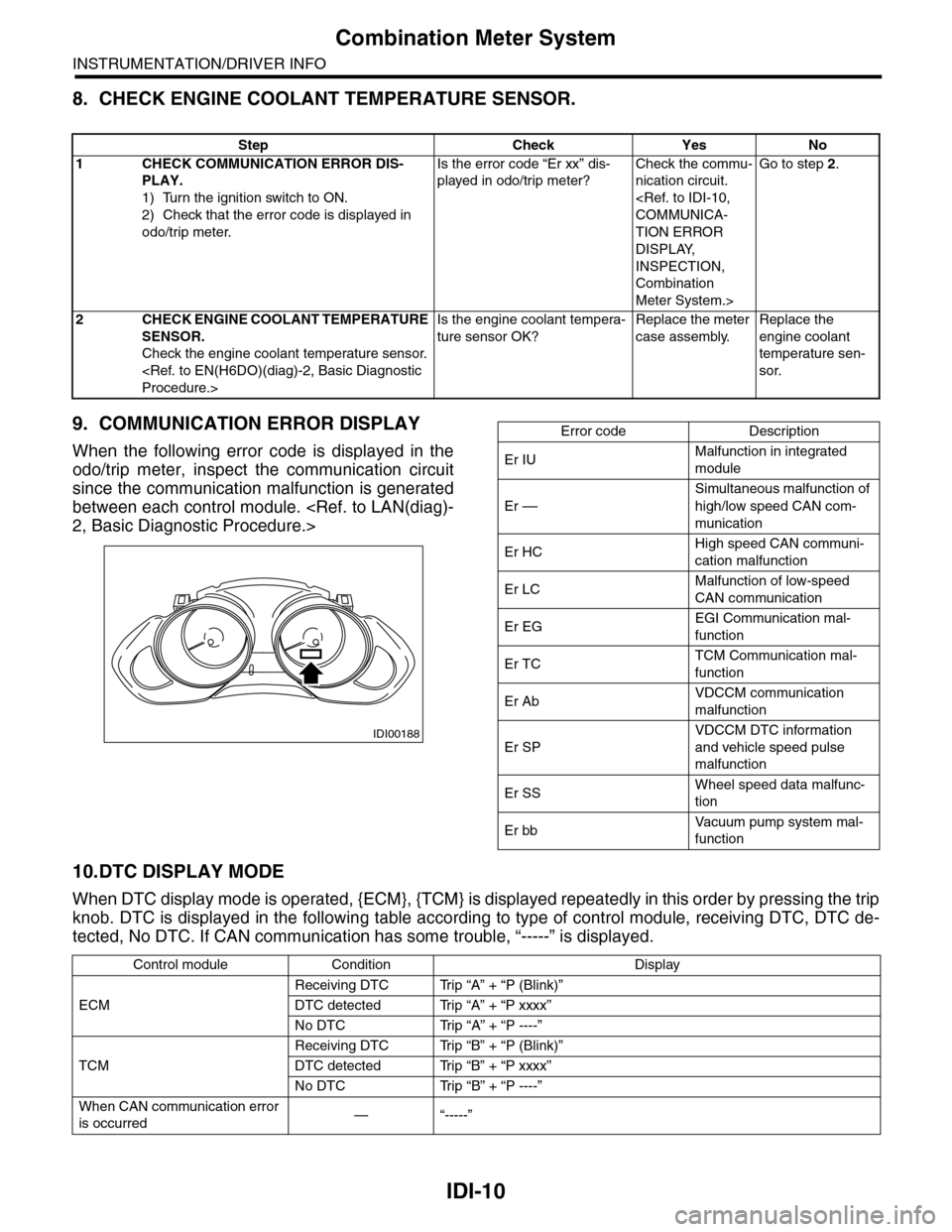
8. CHECK ENGINE COOLANT TEMPERATURE SENSOR.
9. COMMUNICATION ERROR DISPLAY
When the following error code is displayed in the
odo/trip meter, inspect the communication circuit
since the communication malfunction is generated
between each control module.
10.DTC DISPLAY MODE
When DTC display mode is operated, {ECM}, {TCM} is displayed repeatedly in this order by pressing the trip
knob. DTC is displayed in the following table according to type of control module, receiving DTC, DTC de-
tected, No DTC. If CAN communication has some trouble, “-----” is displayed.
Step Check Yes No
1CHECK COMMUNICATION ERROR DIS-
PLAY.
1) Turn the ignition switch to ON.
2) Check that the error code is displayed in
odo/trip meter.
Is the error code “Er xx” dis-
played in odo/trip meter?
Check the commu-
nication circuit.
TION ERROR
DISPLAY,
INSPECTION,
Combination
Meter System.>
Go to step 2.
2CHECK ENGINE COOLANT TEMPERATURE
SENSOR.
Check the engine coolant temperature sensor.
Is the engine coolant tempera-
ture sensor OK?
Replace the meter
case assembly.
Replace the
engine coolant
temperature sen-
sor.
IDI00188
Error code Description
Er IUMalfunction in integrated
module
Er ––
Simultaneous malfunction of
high/low speed CAN com-
munication
Er HCHigh speed CAN communi-
cation malfunction
Er LCMalfunction of low-speed
CAN communication
Er EGEGI Communication mal-
function
Er TCTCM Communication mal-
function
Er AbVDCCM communication
malfunction
Er SP
VDCCM DTC information
and vehicle speed pulse
malfunction
Er SSWheel speed data malfunc-
tion
Er bbVa c u u m p u m p s y s t e m m a l -
function
Control module Condition Display
ECM
Receiving DTC Trip “A” + “P (Blink)”
DTC detected Trip “A” + “P xxxx”
No DTC Trip “A” + “P ----”
TCM
Receiving DTC Trip “B” + “P (Blink)”
DTC detected Trip “B” + “P xxxx”
No DTC Trip “B” + “P ----”
When CAN communication error
is occurred—“-----”
Page 463 of 2453
LAN(diag)-7
Electrical Component Location
LAN SYSTEM (DIAGNOSTICS)
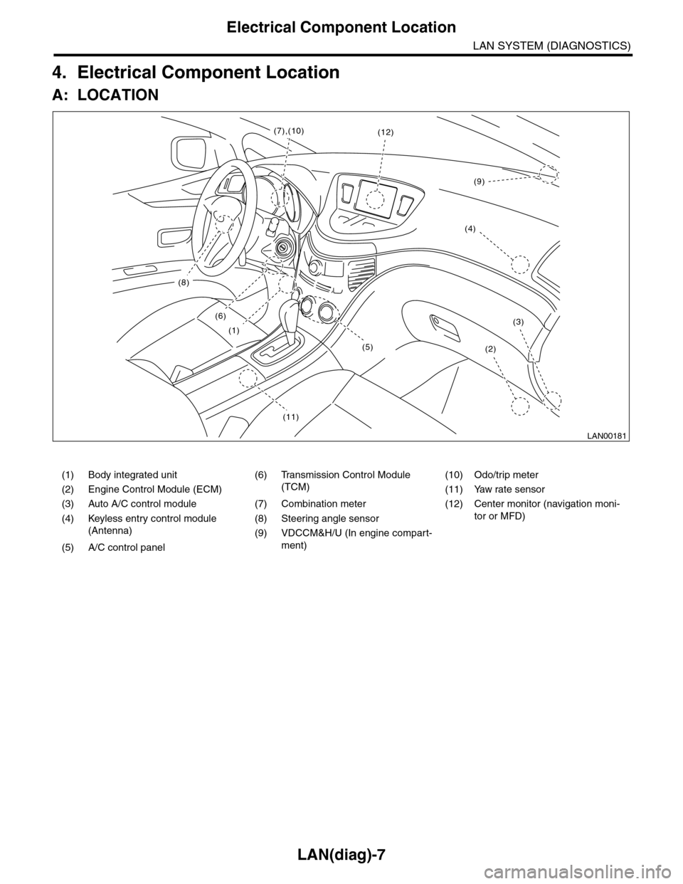
4. Electrical Component Location
A: LOCATION
(1) Body integrated unit (6) Transmission Control Module
(TCM)
(10) Odo/trip meter
(2) Engine Control Module (ECM) (11) Yaw rate sensor
(3) Auto A/C control module (7) Combination meter (12) Center monitor (navigation moni-
tor or MFD)(4) Keyless entry control module
(Antenna)
(8) Steering angle sensor
(9) VDCCM&H/U (In engine compart-
ment)(5) A/C control panel
LAN00181
(8)
(6)
(1)
(11)
(2)
(3)
(12)(7),(10)
(4)
(9)
(5)
Page 466 of 2453
LAN(diag)-10
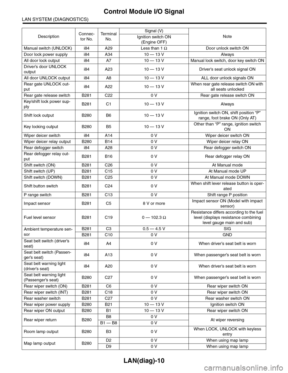
Control Module I/O Signal
LAN SYSTEM (DIAGNOSTICS)
Manual switch (UNLOCK) i84 A29 Less than 1 ΩDoor unlock switch ON
Door lock power supply i84 A34 10 — 13 V Always
All door lock output i84 A7 10 — 13 V Manual lock switch, door key switch ON
Driver’s door UNLOCK
outputi84 A23 10 — 13 V Driver’s seat unlock signal ON
All door UNLOCK output i84 A8 10 — 13 V ALL door unlock signals ON
Rear gate UNLOCK out-
puti84 A22 10 — 13 VWhen rear gate release switch ON with
all seats unlocked
Rear gate release switch B281 C22 0 V Rear gate release switch ON
Key/shift lock power sup-
plyB281 C1 10 — 13 V Always
Shift lock output B280 B6 10 — 13 VIgnition switch ON, shift position “P”
range, foot brake ON (Only AT)
Key locking output B280 B5 10 — 13 VOther than “P” range, ignition switch
ON
Wiper deicer switch i84 A14 0 V Wiper deicer switch ON
Wiper deicer relay output B280 B14 0 V Wiper deicer relay ON
Rear defogger switch i84 A28 0 V Rear defogger switch ON
Rear defogger relay out-
putB281 B16 0 V Rear defogger relay ON
Shift switch (ON) B281 C26 0 V At Manual mode
Shift switch (UP) B281 C15 0 V At Manual mode UP
Shift switch (DOWN) B281 C25 0 V At Manual mode DOWN
Shift button switch B281 C24 0 VWhen shift lever release button is oper-
ated
P range switch B281 C13 0 V Shift range P position
Impact sensor B281 C5 8 V or moreImpact sensor ON (Model with impact
sensor)
Fuel level sensor B281 C19 0 — 102.3 Ω
Resistance differs according to the fuel
level (displays resistance combining
level gauge main and sub)
Ambient temperature sen-
sor
B281 C3 0.5 — 4.5 V SIG
B281 C10 0 V GND
Seat belt switch (driver’s
seat)i84 A4 0 V When driver’s seat belt is worn
Seat belt switch (Passen-
ger’s seat)i84 A13 0 V When passenger’s seat belt is worn
Seat belt warning light
(driver’s seat)i84 A20 0 V When driver’s seat belt is worn
Seat belt warning light
(Passenger’s seat)B280 C27 0 V When passenger’s seat belt is worn
Rear wiper switch (ON) B281 C6 0 V Rear wiper switch ON
Rear wiper switch (INT) B281 C18 0 V Rear wiper switch ON
Rear washer switch B281 C27 0 V Rear washer switch ON
Rear wiper power supply B280 B21 10 — 13 V Ignition switch ON
Rear wiper ON output B280 B1 10 — 13 V Rear wiper switch ON
Rear wiper return B280B8 0 VAt wiper reversingB1 — B8 0 V
Room lamp output B280 B3 0 VWhen LOCK, UNLOCK with keyless
entry
Map lamp output B280D2 0 V When using map lamp
D9 0 V When using map lamp
DescriptionConnec-
tor No.
Te r m i n a l
No.
Signal (V)
NoteIgnition switch ON
(Engine OFF)
Page 469 of 2453
![SUBARU TRIBECA 2009 1.G Service Owners Manual LAN(diag)-13
Subaru Select Monitor
LAN SYSTEM (DIAGNOSTICS)
2. READ CURRENT DATA
1) On the «Main Menu» display screen, select the {Each System Check} and press the [YES] key.
2) On the «System Sele SUBARU TRIBECA 2009 1.G Service Owners Manual LAN(diag)-13
Subaru Select Monitor
LAN SYSTEM (DIAGNOSTICS)
2. READ CURRENT DATA
1) On the «Main Menu» display screen, select the {Each System Check} and press the [YES] key.
2) On the «System Sele](/img/17/7322/w960_7322-468.png)
LAN(diag)-13
Subaru Select Monitor
LAN SYSTEM (DIAGNOSTICS)
2. READ CURRENT DATA
1) On the «Main Menu» display screen, select the {Each System Check} and press the [YES] key.
2) On the «System Selection Menu» display screen, select the {Integ. Unit mode} and press the [YES] key.
3) On the «Integ. unit mode failure diag» display screen, select the {Current Data Display & Save} and press
the [YES] key.
4) On the «Current Data Display & Save» display screen, select the {12 Data Display} and press the [YES]
key.
5) Using the scroll key, scroll the display screen up or down until the desired data is shown.
•A support list contains both of analog and digital data, and they are shown in the following table.
3. DISPLAY OF ANALOG DATA
Items to be displayed Unit of measure Description Note
BATT Voltage (Control) 10 — 15 VBody integrated unit input
valueAlways
BATT Voltage (BACK UP) 10 — 15 VBody integrated unit input
valueAlways
IG power supply voltage 10 — 15 VBody integrated unit input
valueIgnition switch ON
ACC voltage 10 — 15 VBody integrated unit input
valueIgnition switch ACC
Illumination VR voltage 0 — 5 VBody integrated unit out-
put valueSmall light switch ON
Illumi. output d-ratio 0 — 100%Body integrated unit input
value
Small light ON
Illumination volume is other than bright.
Ambient temp sensor V 0 — 5 VBody integrated unit out-
put valueIgnition switch ON
Ambient temperature –40 — 87.5°CBody integrated unit out-
put valueIgnition switch ON
Fuel level voltage 0 — 8 VBody integrated unit input
valueIgnition switch ON
Fuel level resistance 0 — 102.3 ΩBody integrated unit input
valueIgnition switch ON
key-lock solenoid V 6 — 12 VBody integrated unit out-
put value
Other than parking range
Ignition ON
number of regist. 0 — 4 Key No. to register
Fr o nt W he e l S p ee d km / h C A N d a t a i np u t val u e R ec ep t io n f r o m V DC u ni t
VDC/ABS latest f-codeDTC display (Tempo-
rarily)CAN data input value
It is normal when DTC is not been input
even if this code is displayed.
Reception from VDC
Blower fan steps 0 — 2 levels CAN data input value0: OFF, 1: Low, 2: 2 levels or more
Reception from air conditioner ECM
Fuel level resistance2 0 — 102.3 ΩCAN data output value Reception from body integrated unit
Fuel consumption cc/s CAN data input valueReception from ECM and transmission to
center monitor
Coolant Temp. 40 — 130°C CAN data input value Reception from ECM
Ve h i c l e l a t e r a l Gm/s2CAN data input value Reception from VDC unit
SPORT Shift Stages 0 — 7 levels CAN data input value
(0: Light OFF; 1 — 5: Gear display; 6: Fail; 7:
AT F t e m p e r a t u r e H i g h / L o w )
Reception from TCM
Shift Position 0 — 7 levels CAN data input value
0: 1; 1: 2; 2: 3; 3: 4; 4: D; 5: N; 6: R; 7: P shift
position (There is no 8 input.)
Reception from TCM
Off delay timeOFF, Short, Normal,
Long
Body integrated unit set-
ting itemsCustomize setting
Auto lock time20, 30, 40, 50, 60 sec-
onds
Body integrated unit set-
ting itemsCustomize setting
Page 473 of 2453
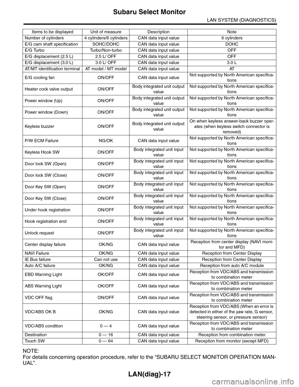
LAN(diag)-17
Subaru Select Monitor
LAN SYSTEM (DIAGNOSTICS)
NOTE:
For details concerning operation procedure, refer to the “SUBARU SELECT MONITOR OPERATION MAN-
UAL”.
Number of cylinders 4 cylinders/6 cylinders CAN data input value 6 cylinders
E/G cam shaft specification SOHC/DOHC CAN data input value DOHC
E/G Turbo Turbo/Non-turbo CAN data input value OFF
E/G displacement (2.5 L) 2.5 L/ OFF CAN data input value OFF
E/G displacement (3.0 L) 3.0 L/ OFF CAN data input value 3.0 L
AT / M T i d e n t i f i c a t i o n t e r m i n a l AT m o d e l / M T m o d e l C A N d a t a i n p u t v a l u e AT
E/G cooling fan ON/OFF CAN data input valueNot supported by North American specifica-
tions
Heater cock valve output ON/OFFBody integrated unit output
value
Not supported by North American specifica-
tions
Pow er w i nd ow (U p) O N /O FFBody integrated unit output
value
Not supported by North American specifica-
tions
Pow er w i nd ow (D ow n ) O N /O FFBody integrated unit output
value
Not supported by North American specifica-
tions
Keyless buzzer ON/OFFBody integrated unit output
value
On when keyless answer-back buzzer oper-
ates (when keyless switch connector is
removed)
P/W ECM Failure NG/OK CAN data input valueNot supported by North American specifica-
tions
Keyless Hook SW ON/OFFBody integrated unit input
value
Not supported by North American specifica-
tions
Door lock SW (Open) ON/OFFBody integrated unit input
value
Not supported by North American specifica-
tions
Door lock SW (Close) ON/OFFBody integrated unit input
value
Not supported by North American specifica-
tions
Door Key SW (Open) ON/OFFBody integrated unit input
value
Not supported by North American specifica-
tions
Door Key SW (Close) ON/OFFBody integrated unit input
value
Not supported by North American specifica-
tions
Under hook registration ON/OFFBody integrated unit input
value
Not supported by North American specifica-
tions
Hook registration end ON/OFFBody integrated unit input
value
Not supported by North American specifica-
tions
Unlock request ON/OFFBody integrated unit input
value
Not supported by North American specifica-
tions
Center display failure OK/NG CAN data input valueReception from center display (NAVI moni-
tor and MFD)
NAVI Failure OK/NG CAN data input value Reception from Center Display
IE Bus failure Can not use CAN data input value Reception from Center Display
Auto A/C failure OK/NG C AN data input value Reception from auto A/C module
EBD Warning Light OK/OFF CAN data input valueReception from VDC/ABS and transmission
to combination meter
ABS Warning Light OK/OFF CAN data input valueReception from VDC/ABS and transmission
to combination meter
VDC OFF flag ON/OFF CAN data input valueReception from VDC/ABS and transmission
to combination meter
VDC/ABS OK B OK/NG CAN data input value
Reception from VDC/ABS (When an error is
detected in either of the yaw rate, G sensor,
steering sensor, or pressure sensor)
VDC/ABS condition 0 — 4 CAN data input valueReception from VDC/ABS and transmission
to combination meter
Destination 0 — 16 CAN data input value Reception from combination meter
To u c h S W 0 — 6 4 C A N d a t a i n p u t v a l u e R e c e p t i o n f r o m m o n i t o r ( e x c e p t M F D )
Items to be displayed Unit of measure Description Note