sensor SUBARU TRIBECA 2009 1.G Service Workshop Manual
[x] Cancel search | Manufacturer: SUBARU, Model Year: 2009, Model line: TRIBECA, Model: SUBARU TRIBECA 2009 1.GPages: 2453, PDF Size: 46.32 MB
Page 474 of 2453
![SUBARU TRIBECA 2009 1.G Service Workshop Manual LAN(diag)-18
Subaru Select Monitor
LAN SYSTEM (DIAGNOSTICS)
5. CONFIRMATION OF CURRENT SETTING
1) On the «Main Menu» display screen, select the {Each System Check} and press the [YES] key.
2) On the SUBARU TRIBECA 2009 1.G Service Workshop Manual LAN(diag)-18
Subaru Select Monitor
LAN SYSTEM (DIAGNOSTICS)
5. CONFIRMATION OF CURRENT SETTING
1) On the «Main Menu» display screen, select the {Each System Check} and press the [YES] key.
2) On the](/img/17/7322/w960_7322-473.png)
LAN(diag)-18
Subaru Select Monitor
LAN SYSTEM (DIAGNOSTICS)
5. CONFIRMATION OF CURRENT SETTING
1) On the «Main Menu» display screen, select the {Each System Check} and press the [YES] key.
2) On the «System Selection Menu» display screen, select the {Integ. Unit mode} and press the [YES] key.
3) On the «Integ. unit mode failure diag» display screen, select the {Current Data Display & Save} and press
the [YES] key.
4) On the «Current Data Display & Save» display screen, select the {12 Data Display} and press the [YES]
key.
5) Using the scroll key, scroll the display screen up or down until the desired data is shown.
6) Display the following item and record the settings.
Required items for new registration (Except for system not equipped)
Item Item to confirm Remarks
Key No. to register 1 2 3 4 Registered ID type
Off delay OFF Long Normal Short Setting for lighting off time
Auto-lock 60, 50 40, 30, 20 OFF Not suppor ted by Nor th Amer ican specifications (Unit sec.)
Rr defogger op. mode Normal ContinuousNormal: Off at 15 minutes of operation
Continuous: Operations from switch on to off
Wiper deicer op. mode Normal Continuous
Normal: Off at 15 minutes of operation
Continuous: Operations from switch ON to OFF, repeats ON
for 15 minutes, OFF for 2 minutes
Security Alarm Setup ON OFFON: Warning device operation possible
OFF: Warning device does not operate
Impact Sensor Setup ON OFF
ON: Impact sensor operation possible
OFF: Impact sensor does not operate
Tu r n O F F f o r v e h i c l e s n o t e q u i p p e d w i t h a n I m p a c t S e n s o r
Alarm monitor delay set-
tingON OFF
ON: Monitor after a fixed period of time from reception of the
keyless lock signal
OFF: Monitor after reception of the keyless lock signal
Lockout prevention ON OFFON: Lockout prevention operation
OFF: Lockout prevention not operated
Impact Sensor Yes No
Ye s : I m p a c t s e n s o r e q u i p p e d
No: Impact sensor not equipped
Always set to no for vehicles not equipped with the impact sen-
sor.
Siren setting Yes No
Ye s : V e h i c l e e q u i p p e d w i t h s i r e n
No: Vehicle not equipped with siren
The horn does not honk when the warning operates if the vehi-
cle not equipped with a siren is set to ‘Yes’.
Answer-back buzzer
setupON OFFON: Answer-back buzzer operation possible
OFF: Answer-back buzzer not operated
Hazard answer-back
setupON OFFON: Hazard answer-back buzzer operation possible
OFF: Hazard answer-back buzzer not operated
Automatic locking setup ON OFF Not suppor ted by Nor th Amer ican specifications
Ans.-back Buzzer Yes NoYe s : V e h i c l e e q u i p p e d w i t h a n s w e r - b a c k b u z z e r
No: Vehicle not equipped with answer-back buzzer
Auto locking Yes No Not suppor ted by Nor th Amer ican specifications
Door open warning (pre-
vention of batter y run-
out)
Ye s N o
Ye s : D o o r i n t e r l o c k e d r o o m l i g h t g o e s o f f w h e n o n f o r 1 0 m i n -
utes consecutively when door is open.
No: Room light remains illuminated until door is closed.
A/C ECM setting Yes No Model with auto A/C (Set to ‘Yes’)
P/W ECM setting Yes No Not supported by North American specifications
Center display failure Yes NoYe s : V e h i c l e e q u i p p e d w i t h M F D a n d n a v i g a t i o n d i s p l a y
No: Vehicle not equipped with MFD nor navigation display
Wiper deicer Yes NoYe s : V e h i c l e e q u i p p e d w i t h w i p e r d e i c e r
No: Vehicle not equipped with wiper deicer
Rear fog light setting Yes No Not supported by North American specifications
Fac t or y in i ti a l s et t i ng Fa ct o r y M ar ke tDo not change to the factory mode. Set to market when using
normally.
Page 478 of 2453
![SUBARU TRIBECA 2009 1.G Service Workshop Manual LAN(diag)-22
Subaru Select Monitor
LAN SYSTEM (DIAGNOSTICS)
9. FUNCTION SETTING (ECM CUSTOMIZING)
1) On the «Main Menu» display screen, select the {Each System Check} and press the [YES] key.
2) On SUBARU TRIBECA 2009 1.G Service Workshop Manual LAN(diag)-22
Subaru Select Monitor
LAN SYSTEM (DIAGNOSTICS)
9. FUNCTION SETTING (ECM CUSTOMIZING)
1) On the «Main Menu» display screen, select the {Each System Check} and press the [YES] key.
2) On](/img/17/7322/w960_7322-477.png)
LAN(diag)-22
Subaru Select Monitor
LAN SYSTEM (DIAGNOSTICS)
9. FUNCTION SETTING (ECM CUSTOMIZING)
1) On the «Main Menu» display screen, select the {Each System Check} and press the [YES] key.
2) On the «System Selection Menu» display screen, select the {Integ. Unit mode} and press the [YES] key.
3) On the «Integ. Unit mode failure diag» display screen, select the {ECM customizing} and press the [YES] key.
4) Change the setting with UP/DOWN key and press the [YES] key.
•List of function setting item (ECM customizing)
NOTE:
Even if changes are made to items that are not equipped, the contents are not confirmed and do not operate.
DataInitial set-
ting value
Customize
settingRemarksDestination
Specifications
Off delay time Normal
Delay time below can be selected by setting.
After door closed After key unlock
OFF 0 sec. 0 sec.
Short 3 sec. 10 sec.
Normal 5 sec. 20 sec.
Long 8 sec. 30 sec.
Auto lock time 30 sec.0 — 60
sec.
Workable when Auto locking is set to “ON” and Automatic
locking setup is “ON”. Time can be changed by 10 sec-
onds: 0 (OFF) — 60 (maximum).
Not supported by North
American specifications
Rr defogger op.
mode15 min.
15 min.Rear defogger stops in 15 minutes automatically after
switch is turned to ON.
ContinuousRear defogger repeats active condition for 15 minutes and
inactive condition for 2 minutes until switch is turned to OFF.
Wiper deicer op.
mode15 min.
15 min.Wiper deicer stops in 15 minutes automatically after
switch is turned to ON.
ContinuousWiper deicer repeats active condition for 15 minutes and
inactive condition for 2 minutes until switch is turned to OFF.
Security Alarm
SetupONON Security alarm (hazard, horn or siren) in active condition
OFF Security alarm in inactive condition
Impact Sensor
SetupOFF
ONWorkable when Impact Sensor Setup is set to “ON”
Impact sensor in active condition
OFFImpact sensor in inactive condition (Set Impact Sensor
Setup of model without impact sensor to “OFF”.)
Alarm monitor
delay settingON
After doors are locked by keyless entry system operated,
Alarm monitor starts in following time.
ON Delay time is 30 seconds.
OFF Delay time is 0 seconds.
Lockout preven-
tionONONLockout prevention in inactive condition (Lockout preven-
tion does not operate if safety knob is locked by hand.)
OFF Lockout prevention in inactive condition
Impact Sensor OFFON
Ve h i c l e i s c o n t r o l l e d i n i m p a c t s e n s o r e q u i p p e d m o d e .
(Set impact sensor to “OFF” in model without impact sen-
sor. If impact sensor is set to “ON”, hazard, horn or siren
operate after doors are locked by keyless entry system
operated (Alarm monitor starting).
Set to “ON” when an
optional impact sensor
is installed.
OFF Vehicle is controlled in impact sensor no-equipped mode.
Siren setting OFFON
Siren sounds when alarm operates. (Set siren setting to
“OFF” in model without siren. Horn does not sound if siren
setting is set to “ON”.)
Set to “ON” when an
optional siren is
installed.OFF Horn sounds when alarm operates.
Answer-back
buzzer setupON
ON
Workable when answer-back buzzer setup is set to “ON”.
When lock/unlock is selected by keyless entry system
operated, hazard answer-back buzzer operates.
OFFWhen lock/unlock is selected by keyless entry system
operated, answer-back buzzer does not sound.
Page 479 of 2453
LAN(diag)-23
Subaru Select Monitor
LAN SYSTEM (DIAGNOSTICS)
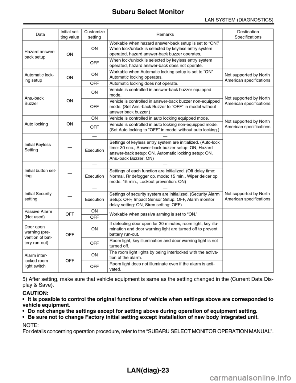
5) After setting, make sure that vehicle equipment is same as the setting changed in the {Current Data Dis-
play & Save}.
CAUTION:
•It is possible to control the original functions of vehicle when settings above are corresponded to
vehicle equipment.
•Do not change the settings except for setting above during operation of equipment setting.
•Be sure not to change Factory initial setting except installation of new body integrated unit.
NOTE:
For details concerning operation procedure, refer to the “SUBARU SELECT MONITOR OPERATION MANUAL”.
Hazard answer-
back setupON
ON
Workable when hazard answer-back setup is set to “ON.”
When lock/unlock is selected by keyless entry system
operated, hazard answer-back buzzer operates.
OFFWhen lock/unlock is selected by keyless entry system
operated, hazard answer-back does not operate.
Automatic lock-
ing setupONONWorkable when Automatic locking setup is set to “ON”
Automatic locking operates.Not supported by North
American specificationsOFF Automatic locking does not operate.
Ans.-back
BuzzerON
ONVe h i c l e i s c o n t r o l l e d i n a n sw e r - b a c k b u z z e r e q u i p p e d
mode.Not supported by North
American specificationsOFF
Ve h i c l e i s c o n t r o l l e d i n a n sw e r - b a c k b u z z e r n o n - e q u i p p e d
mode. (Set Ans.-back Buzzer to “OFF” in model without
answer back buzzer.)
Auto locking ON
ON Vehicle is controlled in auto locking equipped mode.Not supported by North
American specificationsOFFVe h i c l e i s c o n t r o l l e d i n a u t o l o c k i n g n o n - e q u i p p e d m o d e .
(Set Auto locking to “OFF” in model without auto locking.)
Initial Keyless
Setting—
——
Execution
Settings of keyless entry system are initialized. (Auto-lock
time: 30 sec., Answer-back buzzer setup: ON, Hazard
answer-back setup: ON, Automatic locking setup: ON,
Ans.-back Buzzer: ON)
Initial button set-
ting—
——
Execution
Settings of each function are initialized. (Off delay time:
Normal, Rr defogger op. mode: 15 min., Wiper deicer op.
mode: 15 min., Lockout prevention: ON)
Initial Security
setting—
——
Not supported by North
American specificationsExecution
Settings of security system are initialized. (Security Alarm
Setup: OFF, Impact Sensor Setup: OFF, Alarm monitor
delay setting: ON, Siren setting: OFF)
Passive Alar m
(Not used)OFFONWorkable when passive ar ming is set to “ON.”
OFF
Door open
warning (pre-
vention of bat-
tery run-out)
OFF
ON
If detecting door open for 30 minutes, room light, key illu-
mination and door warning light are turned off to prevent
battery run-out.
OFFRoom light, key illumination and door warning light is not
turned off.
Alarm inter-
locked room
light switch
OFF
ONThe room light lights by being interlocked with the activa-
tion of the alarm.
OFFRoom light does not illuminate even if the alarm is acti-
vated.
DataInitial set-
ting value
Customize
settingRemarksDestination
Specifications
Page 502 of 2453
LAN(diag)-46
Diagnostic Procedure with Diagnostic Trouble Code (DTC)
LAN SYSTEM (DIAGNOSTICS)
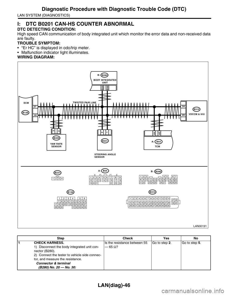
I: DTC B0201 CAN-HS COUNTER ABNORMAL
DTC DETECTING CONDITION:
High speed CAN communication of body integrated unit which monitor the error data and non-received data
are faulty.
TROUBLE SYMPTOM:
•“Er HC” is displayed in odo/trip meter.
•Malfunction indicator light illuminates.
WIRING DIAGRAM:
VDCCM & H/U
B310
B20B30
BODY INTEGRATEDUNIT
B280B:
TCM
B54A:
23
B359
YAW R AT ESENSOR
34
20
B231
21
STEERING ANGLESENSOR
B231
1234
B54A:
12 7 8 9563410 11 1219 20 2113 14 15 16 17 1822 23 24
B136B310
B280B:
5467821931022 23111213141524 25 26 2716171828 29192021 30
ECM
B136
27
35
A3A4
TWISTED PAIR LINE
12345678910 11 12 13 14
15 16 17 18 19 2021 22 23 24 25 26 27 2829 30 31 32 33 3435 36 37 38 39403940
27 28394016101112131415252430
9871718192028212223293231
123456
2726333435
LAN00191
Step Check Yes No
1CHECK HARNESS.
1) Disconnect the body integrated unit con-
nector (B280).
2) Connect the tester to vehicle side connec-
tor, and measure the resistance.
Connector & terminal
(B280) No. 20 — No. 30:
Is the resistance between 55
— 65 Ω?
Go to step 2.Go to step 5.
Page 503 of 2453
LAN(diag)-47
Diagnostic Procedure with Diagnostic Trouble Code (DTC)
LAN SYSTEM (DIAGNOSTICS)
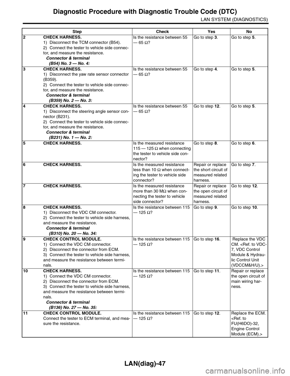
2CHECK HARNESS.
1) Disconnect the TCM connector (B54).
2) Connect the tester to vehicle side connec-
tor, and measure the resistance.
Connector & terminal
(B54) No. 3 — No. 4:
Is the resistance between 55
— 65 Ω?
Go to step 3.Go to step 5.
3CHECK HARNESS.
1) Disconnect the yaw rate sensor connector
(B359).
2) Connect the tester to vehicle side connec-
tor, and measure the resistance.
Connector & terminal
(B359) No. 2 — No. 3:
Is the resistance between 55
— 65 Ω?
Go to step 4.Go to step 5.
4CHECK HARNESS.
1) Disconnect the steering angle sensor con-
nector (B231).
2) Connect the tester to vehicle side connec-
tor, and measure the resistance.
Connector & terminal
(B231) No. 1 — No. 2:
Is the resistance between 55
— 65 Ω?
Go to step 12.Go to step 5.
5CHECK HARNESS.Is the measured resistance
115 — 125 Ω when connecting
the tester to vehicle side con-
nector?
Go to step 8.Go to step 6.
6CHECK HARNESS.Is the measured resistance
less than 10 Ω when connect-
ing the tester to vehicle side
connector?
Repair or replace
the short circuit of
measured related
harness.
Go to step 7.
7CHECK HARNESS.Is the measured resistance
more than 30 MΩ when con-
necting the tester to vehicle
side connector?
Repair or replace
the open circuit of
measured related
harness.
Go to step 12.
8CHECK HARNESS.
1) Disconnect the VDC CM connector.
2) Connect the tester to vehicle side harness,
and measure the resistance.
Connector & terminal
(B310) No. 20 — No. 34:
Is the resistance between 115
— 125 Ω?
Go to step 9.Go to step 10.
9CHECK CONTROL MODULE.
1) Connect the VDC CM connector.
2) Disconnect the connector from ECM.
3) Connect the tester to vehicle side harness,
and measure the resistance between termi-
nals.
Is the resistance between 115
— 125 Ω?
Go to step 16. Replace the VDC
CM.
Module & Hydrau-
lic Control Unit
(VDCCM&H/U).>
10 CHECK HARNESS.
1) Connect the VDC CM connector.
2) Disconnect the connector from ECM.
3) Connect the tester to vehicle side harness,
and measure the resistance between termi-
nals.
Connector & terminal
(B136) No. 27 — No. 35:
Is the resistance between 115
— 125 Ω?
Go to step 11.Repair or replace
the open circuit of
main wiring har-
ness.
11 CHECK CONTROL MODULE.
Connect the tester to ECM terminal, and mea-
sure the resistance.
Is the resistance between 115
— 125 Ω?
Go to step 12.Replace the ECM.
Engine Control
Module (ECM).>
Step Check Yes No
Page 504 of 2453
LAN(diag)-48
Diagnostic Procedure with Diagnostic Trouble Code (DTC)
LAN SYSTEM (DIAGNOSTICS)
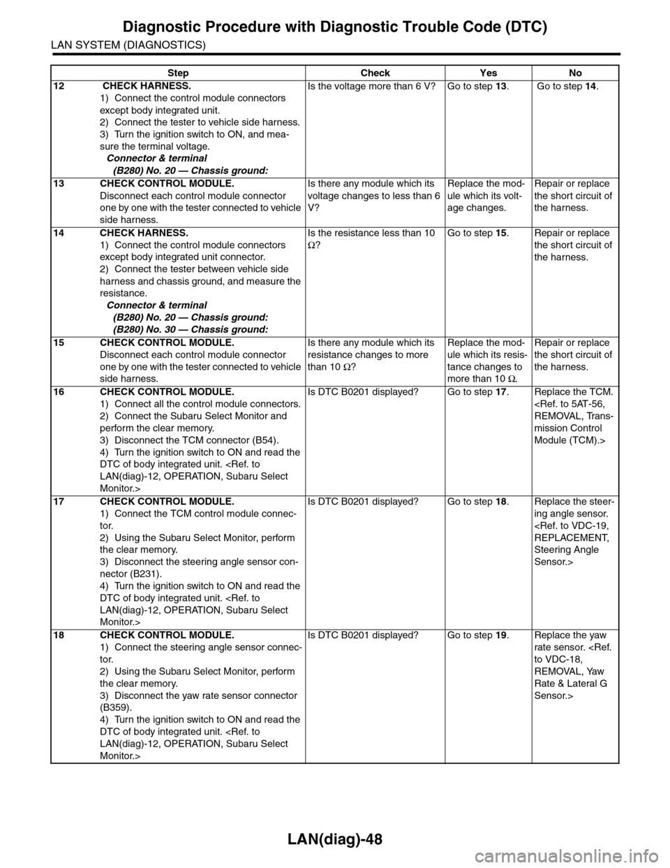
12 CHECK HARNESS.
1) Connect the control module connectors
except body integrated unit.
2) Connect the tester to vehicle side harness.
3) Turn the ignition switch to ON, and mea-
sure the terminal voltage.
Connector & terminal
(B280) No. 20 — Chassis ground:
Is the voltage more than 6 V? Go to step 13. Go to step 14.
13 CHECK CONTROL MODULE.
Disconnect each control module connector
one by one with the tester connected to vehicle
side harness.
Is there any module which its
voltage changes to less than 6
V?
Replace the mod-
ule which its volt-
age changes.
Repair or replace
the shor t circuit of
the harness.
14 CHECK HARNESS.
1) Connect the control module connectors
except body integrated unit connector.
2) Connect the tester between vehicle side
harness and chassis ground, and measure the
resistance.
Connector & terminal
(B280) No. 20 — Chassis ground:
(B280) No. 30 — Chassis ground:
Is the resistance less than 10
Ω?
Go to step 15.Repair or replace
the shor t circuit of
the harness.
15 CHECK CONTROL MODULE.
Disconnect each control module connector
one by one with the tester connected to vehicle
side harness.
Is there any module which its
resistance changes to more
than 10 Ω?
Replace the mod-
ule which its resis-
tance changes to
more than 10 Ω.
Repair or replace
the shor t circuit of
the harness.
16 CHECK CONTROL MODULE.
1) Connect all the control module connectors.
2) Connect the Subaru Select Monitor and
perform the clear memory.
3) Disconnect the TCM connector (B54).
4) Turn the ignition switch to ON and read the
DTC of body integrated unit.
Monitor.>
Is DTC B0201 displayed? Go to step 17.Replace the TCM.
mission Control
Module (TCM).>
17 CHECK CONTROL MODULE.
1) Connect the TCM control module connec-
tor.
2) Using the Subaru Select Monitor, perform
the clear memory.
3) Disconnect the steering angle sensor con-
nector (B231).
4) Turn the ignition switch to ON and read the
DTC of body integrated unit.
Monitor.>
Is DTC B0201 displayed? Go to step 18.Replace the steer-
ing angle sensor.
Steering Angle
Sensor.>
18 CHECK CONTROL MODULE.
1) Connect the steering angle sensor connec-
tor.
2) Using the Subaru Select Monitor, perform
the clear memory.
3) Disconnect the yaw rate sensor connector
(B359).
4) Turn the ignition switch to ON and read the
DTC of body integrated unit.
Monitor.>
Is DTC B0201 displayed? Go to step 19.Replace the yaw
rate sensor.
REMOVAL, Yaw
Rate & Lateral G
Sensor.>
Step Check Yes No
Page 506 of 2453
LAN(diag)-50
Diagnostic Procedure with Diagnostic Trouble Code (DTC)
LAN SYSTEM (DIAGNOSTICS)
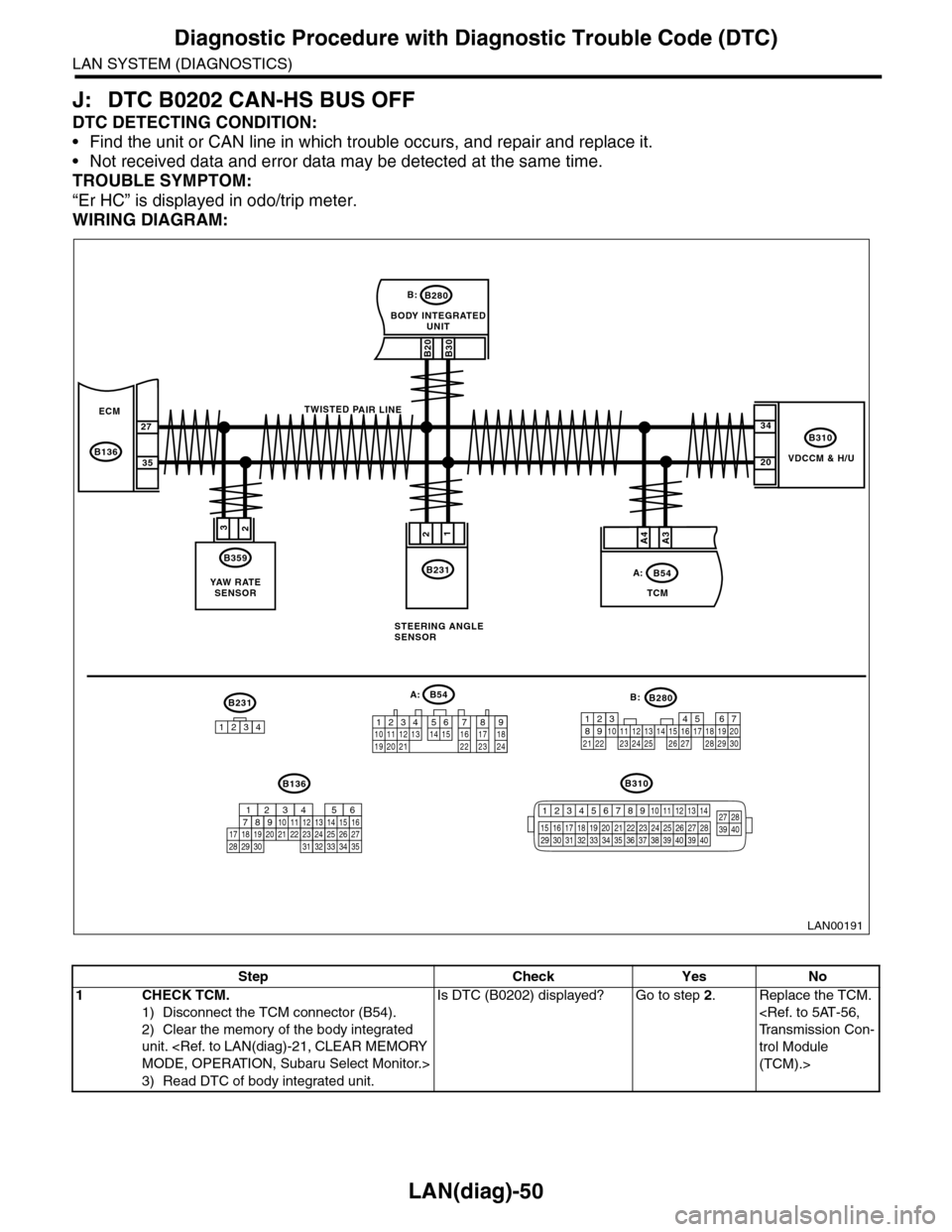
J: DTC B0202 CAN-HS BUS OFF
DTC DETECTING CONDITION:
•Find the unit or CAN line in which trouble occurs, and repair and replace it.
•Not received data and error data may be detected at the same time.
TROUBLE SYMPTOM:
“Er HC” is displayed in odo/trip meter.
WIRING DIAGRAM:
VDCCM & H/U
B310
B20B30
BODY INTEGRATEDUNIT
B280B:
TCM
B54A:
23
B359
YAW R AT ESENSOR
34
20
B231
21
STEERING ANGLESENSOR
B231
1234
B54A:
12 7 8 9563410 11 1219 20 2113 14 15 16 17 1822 23 24
B136B310
B280B:
5467821931022 23111213141524 25 26 2716171828 29192021 30
ECM
B136
27
35
A3A4
TWISTED PAIR LINE
12345678910 11 12 13 14
15 16 17 18 19 2021 22 23 24 25 26 27 2829 30 31 32 33 3435 36 37 38 39403940
27 28394016101112131415252430
9871718192028212223293231
123456
2726333435
LAN00191
Step Check Yes No
1CHECK TCM.
1) Disconnect the TCM connector (B54).
2) Clear the memory of the body integrated
unit.
3) Read DTC of body integrated unit.
Is DTC (B0202) displayed? Go to step 2.Replace the TCM.
trol Module
(TCM).>
Page 507 of 2453
LAN(diag)-51
Diagnostic Procedure with Diagnostic Trouble Code (DTC)
LAN SYSTEM (DIAGNOSTICS)
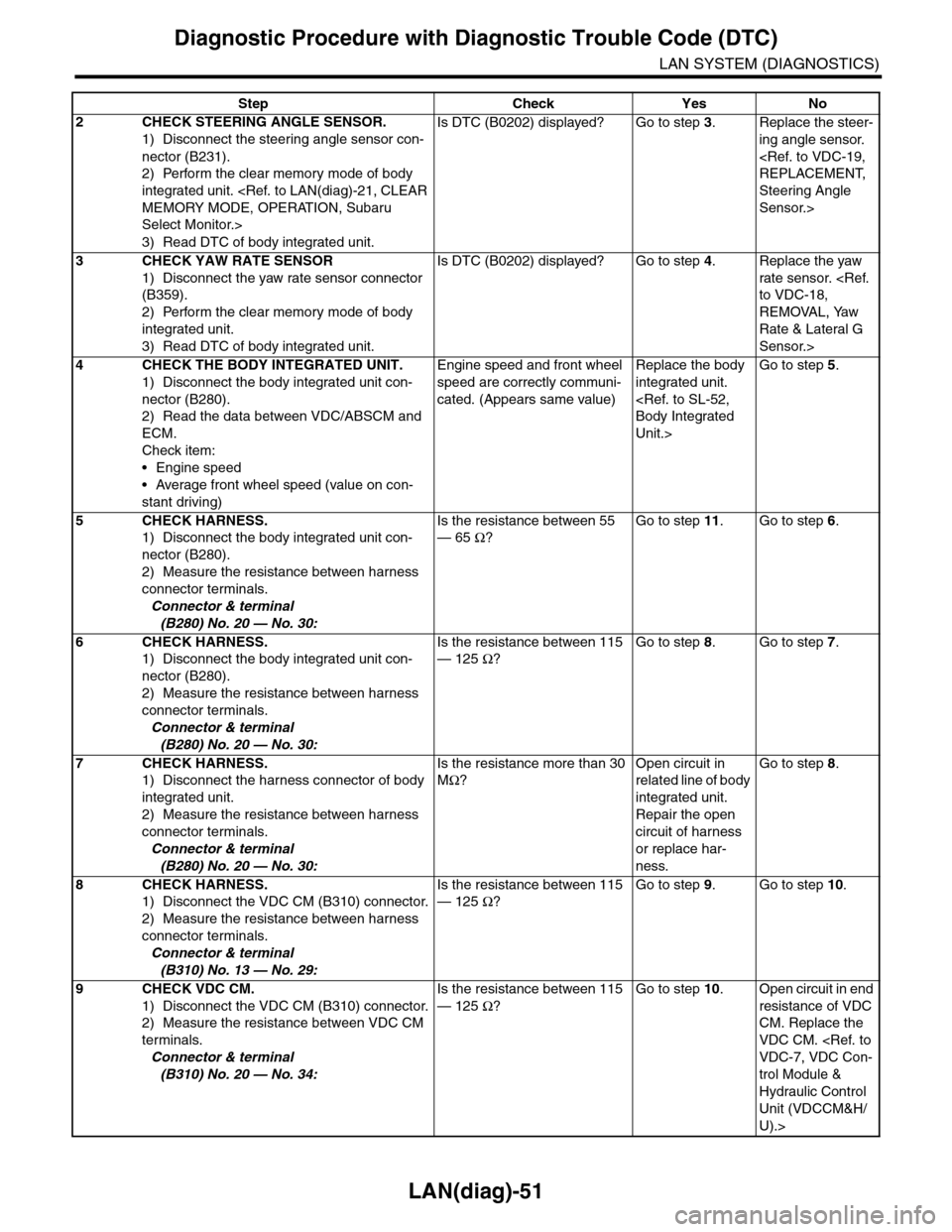
2CHECK STEERING ANGLE SENSOR.
1) Disconnect the steering angle sensor con-
nector (B231).
2) Perform the clear memory mode of body
integrated unit.
Select Monitor.>
3) Read DTC of body integrated unit.
Is DTC (B0202) displayed? Go to step 3.Replace the steer-
ing angle sensor.
Steering Angle
Sensor.>
3CHECK YAW RATE SENSOR
1) Disconnect the yaw rate sensor connector
(B359).
2) Perform the clear memory mode of body
integrated unit.
3) Read DTC of body integrated unit.
Is DTC (B0202) displayed? Go to step 4.Replace the yaw
rate sensor.
REMOVAL, Yaw
Rate & Lateral G
Sensor.>
4CHECK THE BODY INTEGRATED UNIT.
1) Disconnect the body integrated unit con-
nector (B280).
2) Read the data between VDC/ABSCM and
ECM.
Check item:
•Engine speed
•Average front wheel speed (value on con-
stant driving)
Engine speed and front wheel
speed are correctly communi-
cated. (Appears same value)
Replace the body
integrated unit.
Unit.>
Go to step 5.
5CHECK HARNESS.
1) Disconnect the body integrated unit con-
nector (B280).
2) Measure the resistance between harness
connector terminals.
Connector & terminal
(B280) No. 20 — No. 30:
Is the resistance between 55
— 65 Ω?
Go to step 11.Go to step 6.
6CHECK HARNESS.
1) Disconnect the body integrated unit con-
nector (B280).
2) Measure the resistance between harness
connector terminals.
Connector & terminal
(B280) No. 20 — No. 30:
Is the resistance between 115
— 125 Ω?
Go to step 8.Go to step 7.
7CHECK HARNESS.
1) Disconnect the harness connector of body
integrated unit.
2) Measure the resistance between harness
connector terminals.
Connector & terminal
(B280) No. 20 — No. 30:
Is the resistance more than 30
MΩ?
Open circuit in
related line of body
integrated unit.
Repair the open
circuit of harness
or replace har-
ness.
Go to step 8.
8CHECK HARNESS.
1) Disconnect the VDC CM (B310) connector.
2) Measure the resistance between harness
connector terminals.
Connector & terminal
(B310) No. 13 — No. 29:
Is the resistance between 115
— 125 Ω?
Go to step 9.Go to step 10.
9CHECK VDC CM.
1) Disconnect the VDC CM (B310) connector.
2) Measure the resistance between VDC CM
terminals.
Connector & terminal
(B310) No. 20 — No. 34:
Is the resistance between 115
— 125 Ω?
Go to step 10.Open circuit in end
resistance of VDC
CM. Replace the
VDC CM.
trol Module &
Hydraulic Control
Unit (VDCCM&H/
U).>
Step Check Yes No
Page 509 of 2453
LAN(diag)-53
Diagnostic Procedure with Diagnostic Trouble Code (DTC)
LAN SYSTEM (DIAGNOSTICS)
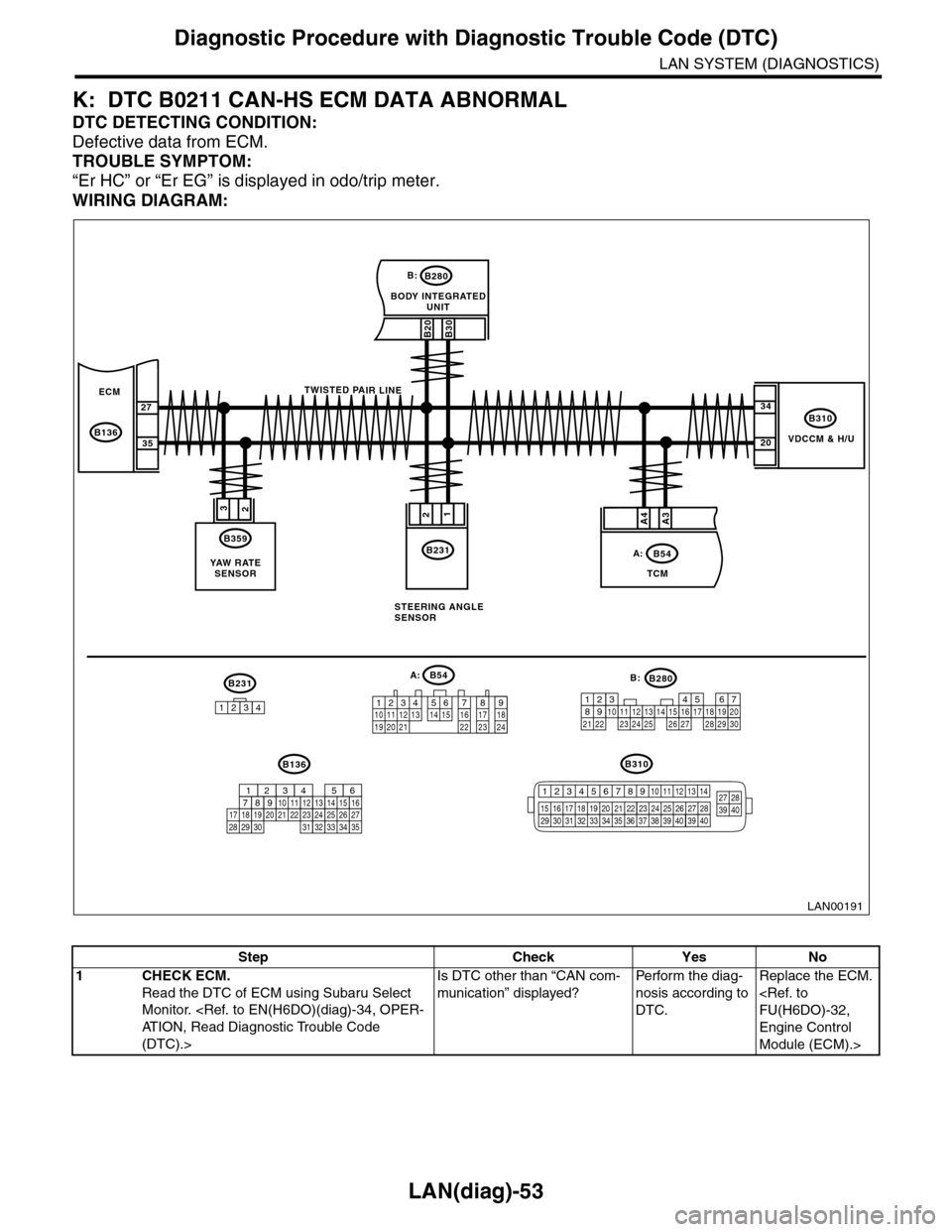
K: DTC B0211 CAN-HS ECM DATA ABNORMAL
DTC DETECTING CONDITION:
Defective data from ECM.
TROUBLE SYMPTOM:
“Er HC” or “Er EG” is displayed in odo/trip meter.
WIRING DIAGRAM:
VDCCM & H/U
B310
B20B30
BODY INTEGRATEDUNIT
B280B:
TCM
B54A:
23
B359
YAW R AT ESENSOR
34
20
B231
21
STEERING ANGLESENSOR
B231
1234
B54A:
12 7 8 9563410 11 1219 20 2113 14 15 16 17 1822 23 24
B136B310
B280B:
5467821931022 23111213141524 25 26 2716171828 29192021 30
ECM
B136
27
35
A3A4
TWISTED PAIR LINE
12345678910 11 12 13 14
15 16 17 18 19 2021 22 23 24 25 26 27 2829 30 31 32 33 3435 36 37 38 39403940
27 28394016101112131415252430
9871718192028212223293231
123456
2726333435
LAN00191
Step Check Yes No
1CHECK ECM.
Read the DTC of ECM using Subaru Select
Monitor.
(DTC).>
Is DTC other than “CAN com-
munication” displayed?
Pe r for m t h e d ia g -
nosis according to
DTC.
Replace the ECM.
Engine Control
Module (ECM).>
Page 510 of 2453
LAN(diag)-54
Diagnostic Procedure with Diagnostic Trouble Code (DTC)
LAN SYSTEM (DIAGNOSTICS)
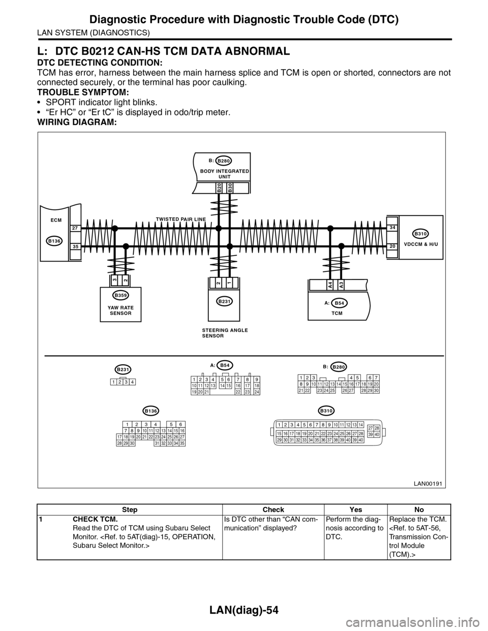
L: DTC B0212 CAN-HS TCM DATA ABNORMAL
DTC DETECTING CONDITION:
TCM has error, harness between the main harness splice and TCM is open or shorted, connectors are not
connected securely, or the terminal has poor caulking.
TROUBLE SYMPTOM:
•SPORT indicator light blinks.
•“Er HC” or “Er tC” is displayed in odo/trip meter.
WIRING DIAGRAM:
VDCCM & H/U
B310
B20B30
BODY INTEGRATEDUNIT
B280B:
TCM
B54A:
23
B359
YAW R AT ESENSOR
34
20
B231
21
STEERING ANGLESENSOR
B231
1234
B54A:
12 7 8 9563410 11 1219 20 2113 14 15 16 17 1822 23 24
B136B310
B280B:
5467821931022 23111213141524 25 26 2716171828 29192021 30
ECM
B136
27
35
A3A4
TWISTED PAIR LINE
12345678910 11 12 13 14
15 16 17 18 19 2021 22 23 24 25 26 27 2829 30 31 32 33 3435 36 37 38 39403940
27 28394016101112131415252430
9871718192028212223293231
123456
2726333435
LAN00191
Step Check Yes No
1CHECK TCM.
Read the DTC of TCM using Subaru Select
Monitor.
Is DTC other than “CAN com-
munication” displayed?
Pe r for m t h e d ia g -
nosis according to
DTC.
Replace the TCM.
trol Module
(TCM).>