SUBARU TRIBECA 2009 1.G Service Workshop Manual
Manufacturer: SUBARU, Model Year: 2009, Model line: TRIBECA, Model: SUBARU TRIBECA 2009 1.GPages: 2453, PDF Size: 46.32 MB
Page 911 of 2453
PS-31
Steering Gearbox
POWER ASSISTED SYSTEM (POWER STEERING)
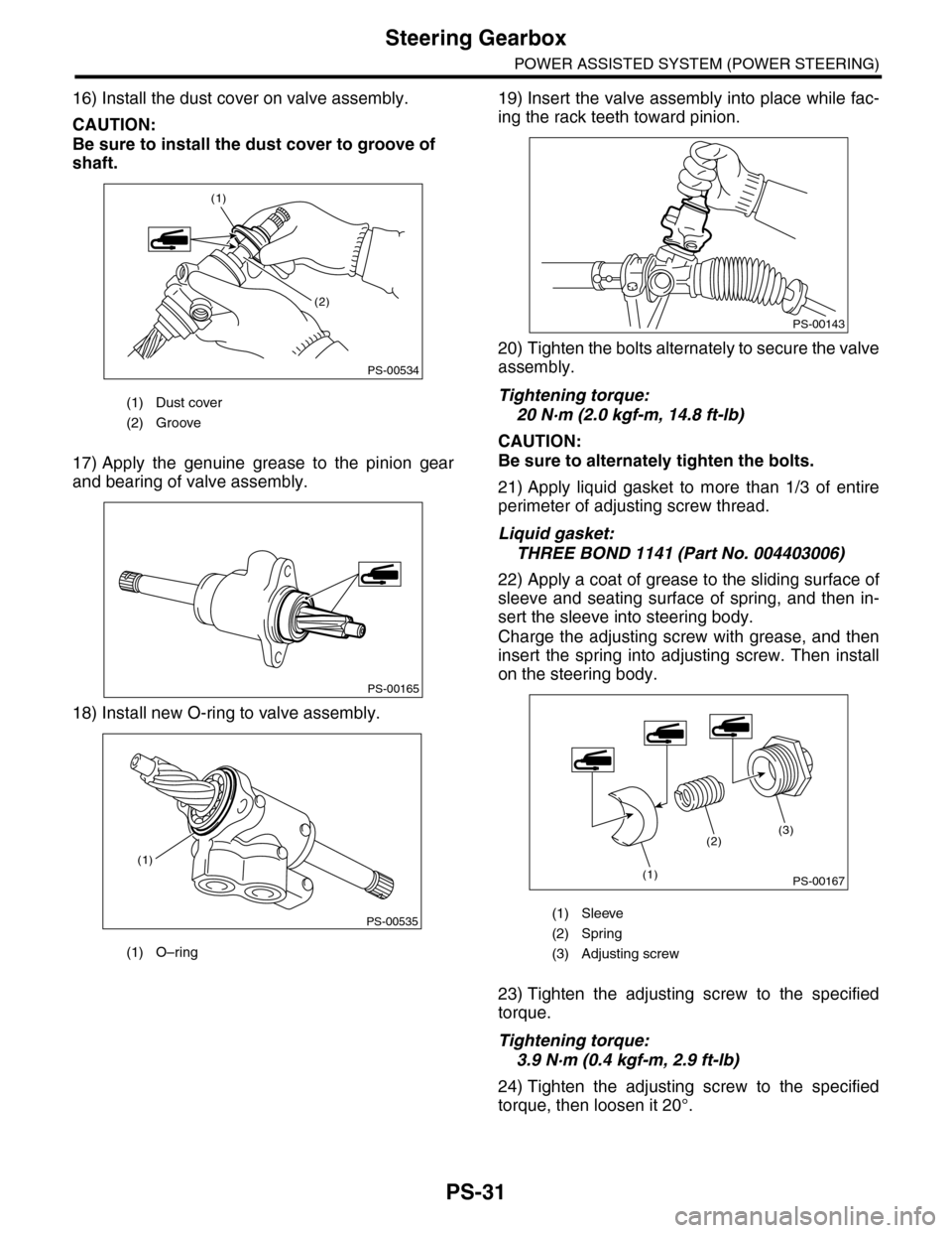
16) Install the dust cover on valve assembly.
CAUTION:
Be sure to install the dust cover to groove of
shaft.
17) Apply the genuine grease to the pinion gear
and bearing of valve assembly.
18) Install new O-ring to valve assembly.
19) Insert the valve assembly into place while fac-
ing the rack teeth toward pinion.
20) Tighten the bolts alternately to secure the valve
assembly.
Tightening torque:
20 N·m (2.0 kgf-m, 14.8 ft-lb)
CAUTION:
Be sure to alternately tighten the bolts.
21) Apply liquid gasket to more than 1/3 of entire
perimeter of adjusting screw thread.
Liquid gasket:
THREE BOND 1141 (Part No. 004403006)
22) Apply a coat of grease to the sliding surface of
sleeve and seating surface of spring, and then in-
sert the sleeve into steering body.
Charge the adjusting screw with grease, and then
insert the spring into adjusting screw. Then install
on the steering body.
23) Tighten the adjusting screw to the specified
torque.
Tightening torque:
3.9 N·m (0.4 kgf-m, 2.9 ft-lb)
24) Tighten the adjusting screw to the specified
torque, then loosen it 20°.
(1) Dust cover
(2) Groove
(1) O–ring
PS-00534
(1)
(2)
PS-00165
PS-00535
(1)
(1) Sleeve
(2) Spring
(3) Adjusting screw
PS-00143
PS-00167
(2)
(1)
(3)
Page 912 of 2453
PS-32
Steering Gearbox
POWER ASSISTED SYSTEM (POWER STEERING)
25) Adjust the turning resistance of gearbox so that
it is within specification using adjusting screw.
26) Apply liquid gasket to lock nut and install it into
adjusting screw. While holding the adjusting screw
with wrench, tighten the lock nut using ST.
Liquid gasket:
THREE BOND 1141
ST 926230000 SPANNER
Tightening torque (lock nut):
25 N·m (2.5 kgf-m, 18.1 ft-lb)
NOTE:
Hold the adjusting screw with a wrench to prevent it
from turning while tightening lock nut.
27) Remove the gearbox from ST.
ST1 926200000 STAND
ST2 34199AG000 BOSS D
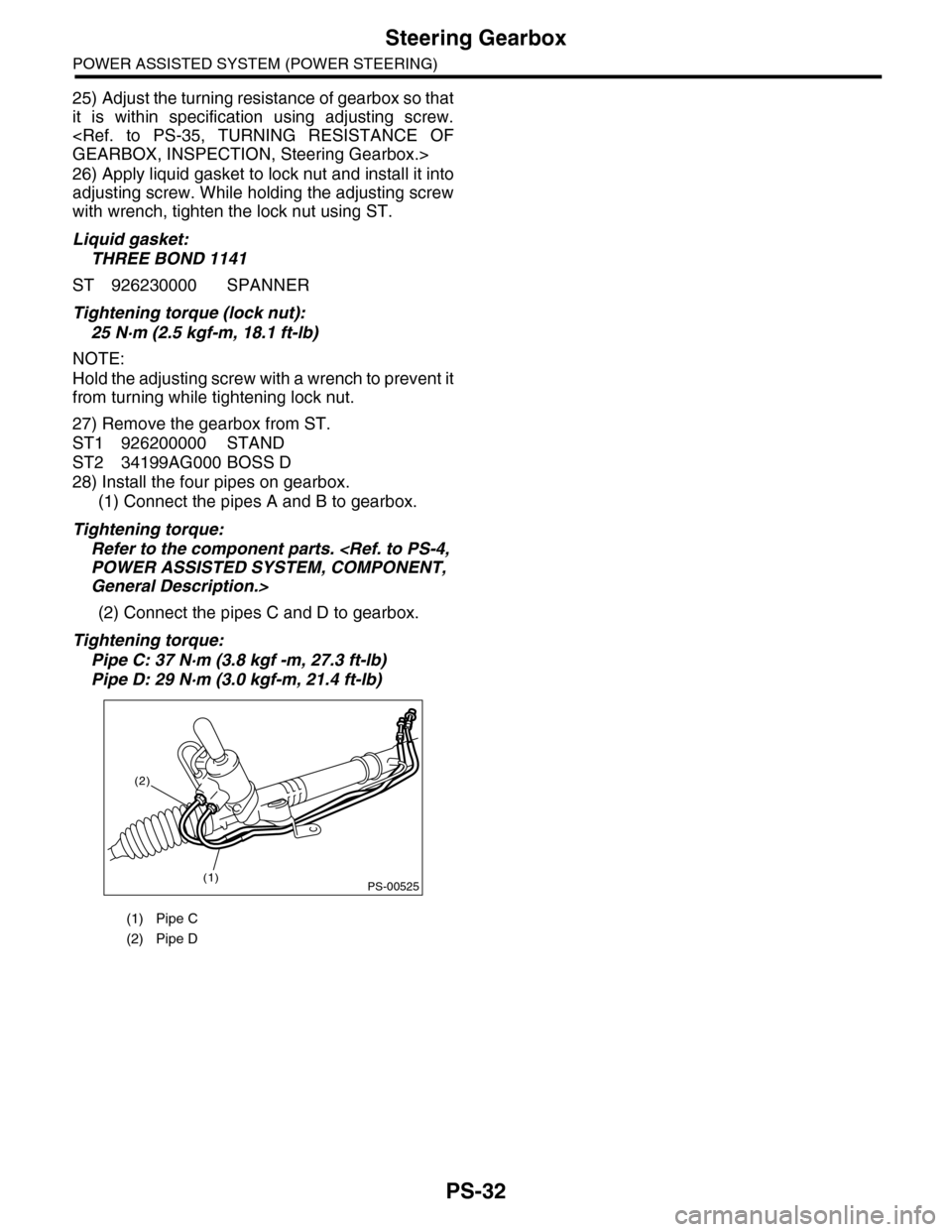
28) Install the four pipes on gearbox.
(1) Connect the pipes A and B to gearbox.
Tightening torque:
Refer to the component parts.
General Description.>
(2) Connect the pipes C and D to gearbox.
Tightening torque:
Pipe C: 37 N·m (3.8 kgf -m, 27.3 ft-lb)
Pipe D: 29 N·m (3.0 kgf-m, 21.4 ft-lb)
(1) Pipe C
(2) Pipe D
PS-00525(1)
(2)
Page 913 of 2453
PS-33
Steering Gearbox
POWER ASSISTED SYSTEM (POWER STEERING)
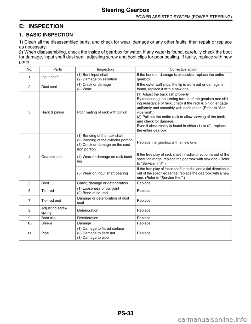
E: INSPECTION
1. BASIC INSPECTION
1) Clean all the disassembled parts, and check for wear, damage or any other faults, then repair or replace
as necessary.
2) When disassembling, check the inside of gearbox for water. If any water is found, carefully check the boot
for damage, input shaft dust seal, adjusting screw and boot clips for poor sealing. If faulty, replace with new
parts.
No. Parts Inspection Corrective action
1Input shaft(1) Bent input shaft
(2) Damage on serration
If the bend or damage is excessive, replace the entire
gearbox.
2Dust seal(1) Crack or damage
(2) Wear
If the outer wall slips, the lip is worn out or damage is
found, replace it with a new one.
3Rack & pinion Poor mating of rack with pinion
(1) Adjust the backlash properly.
By measuring the turning torque of the gearbox and slid-
ing resistance of rack, check if the rack & pinion engage
uniformly and smoothly with each other. (Refer to “Ser-
vice limit”.)
(2) Pull out the entire rack to allow viewing of the teeth,
and check for damage.
Even if abnormality is found in either (1) or (2), replace
the entire gearbox.
4Gearbox unit
(1) Bending of the rack shaft
(2) Bending of the cylinder portion
(3) Crack or damage on the cast
iron portion
Replace the gearbox with a new one.
(4) Wear or damage on rack bush-
ing
If the free play of rack shaft in radial direction is out of the
specified range, replace the gearbox with new one. (Refer
to “Service limit”.)
(5) Wear on input shaft bearing
If the free play of input shaft in radial and axial direction is
out of the specified range, replace the gearbox with a new
one. (Refer to “Service limit”.)
5Boot Crack, damage or deteriorationReplace.
6Tie–rod(1) Looseness of ball joint
(2) Bend of tie–rodReplace.
7Tie–rod endDamage or deterioration of dust
sealReplace.
8Adjusting screw
springDeterioration Replace.
9Boot clip Deterioration Replace.
10 Sleeve Damage Replace.
11 Pipe
(1) Damage to flared surface
(2) Damage to flare nut
(3) Damage to pipe
Replace.
Page 914 of 2453
PS-34
Steering Gearbox
POWER ASSISTED SYSTEM (POWER STEERING)
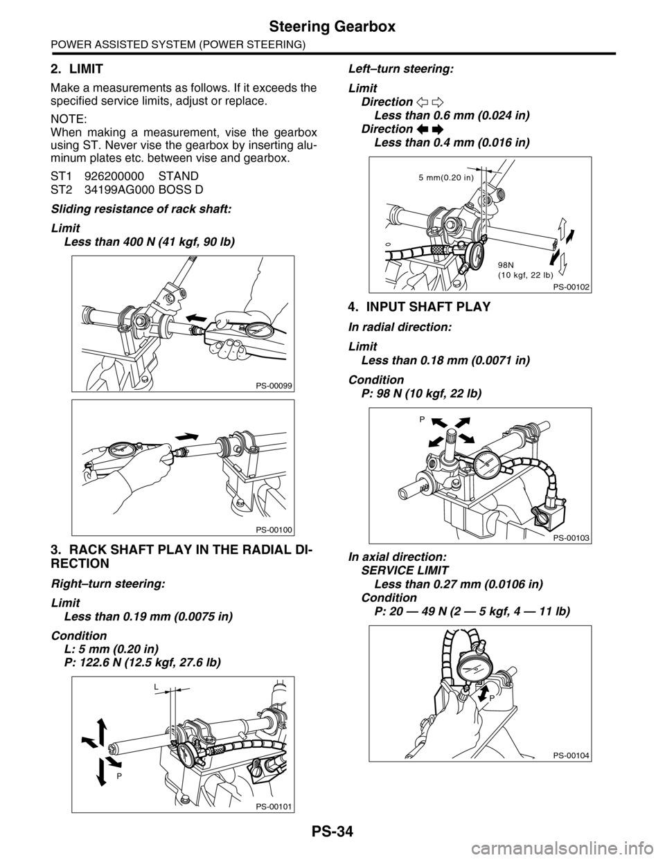
2. LIMIT
Make a measurements as follows. If it exceeds the
specified service limits, adjust or replace.
NOTE:
When making a measurement, vise the gearbox
using ST. Never vise the gearbox by inserting alu-
minum plates etc. between vise and gearbox.
ST1 926200000 STAND
ST2 34199AG000 BOSS D
Sliding resistance of rack shaft:
Limit
Less than 400 N (41 kgf, 90 lb)
3. RACK SHAFT PLAY IN THE RADIAL DI-
RECTION
Right–turn steering:
Limit
Less than 0.19 mm (0.0075 in)
Condition
L: 5 mm (0.20 in)
P: 122.6 N (12.5 kgf, 27.6 lb)
Left–turn steering:
Limit
Direction
Less than 0.6 mm (0.024 in)
Direction
Less than 0.4 mm (0.016 in)
4. INPUT SHAFT PLAY
In radial direction:
Limit
Less than 0.18 mm (0.0071 in)
Condition
P: 98 N (10 kgf, 22 lb)
In axial direction:
SERVICE LIMIT
Less than 0.27 mm (0.0106 in)
Condition
P: 20 — 49 N (2 — 5 kgf, 4 — 11 lb)
PS-00099
PS-00100
PS-00101
P
L
PS-00102
5 mm(0.20 in)
98N(10 kgf, 22 lb)
PS-00103
P
PS-00104
P
Page 915 of 2453
PS-35
Steering Gearbox
POWER ASSISTED SYSTEM (POWER STEERING)
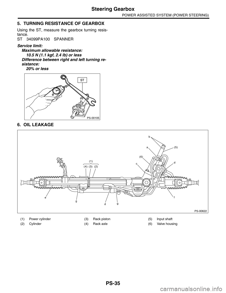
5. TURNING RESISTANCE OF GEARBOX
Using the ST, measure the gearbox turning resis-
tance.
ST 34099PA100 SPANNER
Service limit:
Maximum allowable resistance:
10.5 N (1.1 kgf, 2.4 lb) or less
Difference between right and left turning re-
sistance:
20% or less
6. OIL LEAKAGE
PS-00105
(1) Power cylinder (3) Rack piston (5) Input shaft
(2) Cylinder (4) Rack axle (6) Valve housing
PS-00622
(4) (3) (2)
(5)
(6)
cd
a
b
(1)
fggd
e
Page 916 of 2453
PS-36
Steering Gearbox
POWER ASSISTED SYSTEM (POWER STEERING)
1) Lift-up the vehicle.
2) If a fluid leak is found, clean the fluid completely
from the suspect area, and turn the steering wheel
approx. 30 to 40 times to the left and right from lock
to lock, with the engine running, and check again
for leaks immediately, and also after a few hours
have passed.
3) Cause and solution for oil leakage from “a”
The oil seal is damaged. Replace the valve assem-
bly with a new one.
4) Cause and solution for oil leakage from “b”.
The torsion bar O–ring is damaged. Replace the
valve assembly with a new one.
5) Cause and solution for oil leakage from “c”.
The oil seal is damaged. Replace the valve assem-
bly or oil seal with a new one.
6) Cause and solution for oil leakage from “d”.
The pipe is damaged. Replace the faulty pipe or O-
ring.
7) Cause and solution for oil leakage from “g”.
The hose is damaged. Replace the hose with a
new one.
8) If leak is other than a, b, c, d or g, or if oil is leak-
ing from gearbox, move the right and left boots to-
ward tie-rod end side, respectively, with the
gearbox mounted to the vehicle, and remove fluid
from surrounding portions. Then, turn the steering
wheel from lock to lock about thirty to forty times
with the engine running, and make comparison of
the leaked portion immediately after and several
hours after this operation.
(1) Leakage from “e”
The cylinder seal is damaged. Replace the rack
bushing with a new one.
(2) Leakage from “f”
There are two possible causes. Perform the fol-
lowing step first. Remove the pipe assembly B
from the valve housing, and close the circuit us-
ing ST.
ST 926420000 PLUG
Turn the steering wheel from lock to lock ap-
prox. 30 to 40 times with the engine running,
then inspect the leaked portion immediately af-
ter and several hours after this operation.
•If leakage from “f” is noted again:
The oil seal of pinion & valve assembly is dam-
aged. Replace the pinion & valve assembly with a
new one. Or replace the oil seal and the parts that
are damaged during disassembly with new ones.
•If oil stops leaking from “f”:
The oil seal of rack housing is damaged. Replace
the oil seal and parts that are damaged during dis-
assembly with new ones.
F: ADJUSTMENT
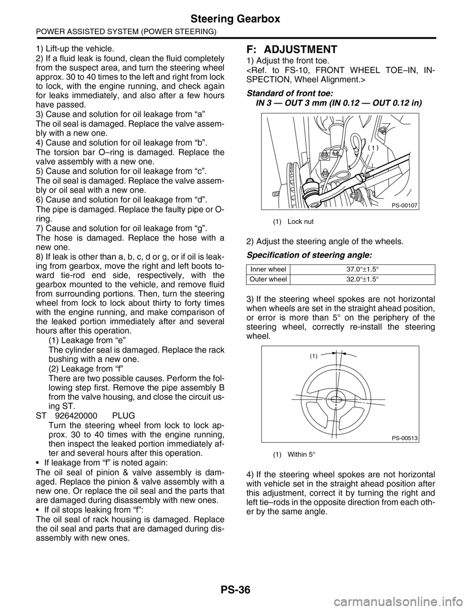
1) Adjust the front toe.
Standard of front toe:
IN 3 — OUT 3 mm (IN 0.12 — OUT 0.12 in)
2) Adjust the steering angle of the wheels.
Specification of steering angle:
3) If the steering wheel spokes are not horizontal
when wheels are set in the straight ahead position,
or error is more than 5° on the periphery of the
steering wheel, correctly re-install the steering
wheel.
4) If the steering wheel spokes are not horizontal
with vehicle set in the straight ahead position after
this adjustment, correct it by turning the right and
left tie–rods in the opposite direction from each oth-
er by the same angle.
(1) Lock nut
Inner wheel 37.0°±1.5°
Outer wheel 32.0°±1.5°
(1) Within 5°
PS-00107
PS-00513
(1)
Page 917 of 2453
PS-37
Pipe Assembly
POWER ASSISTED SYSTEM (POWER STEERING)
6. Pipe Assembly
A: REMOVAL
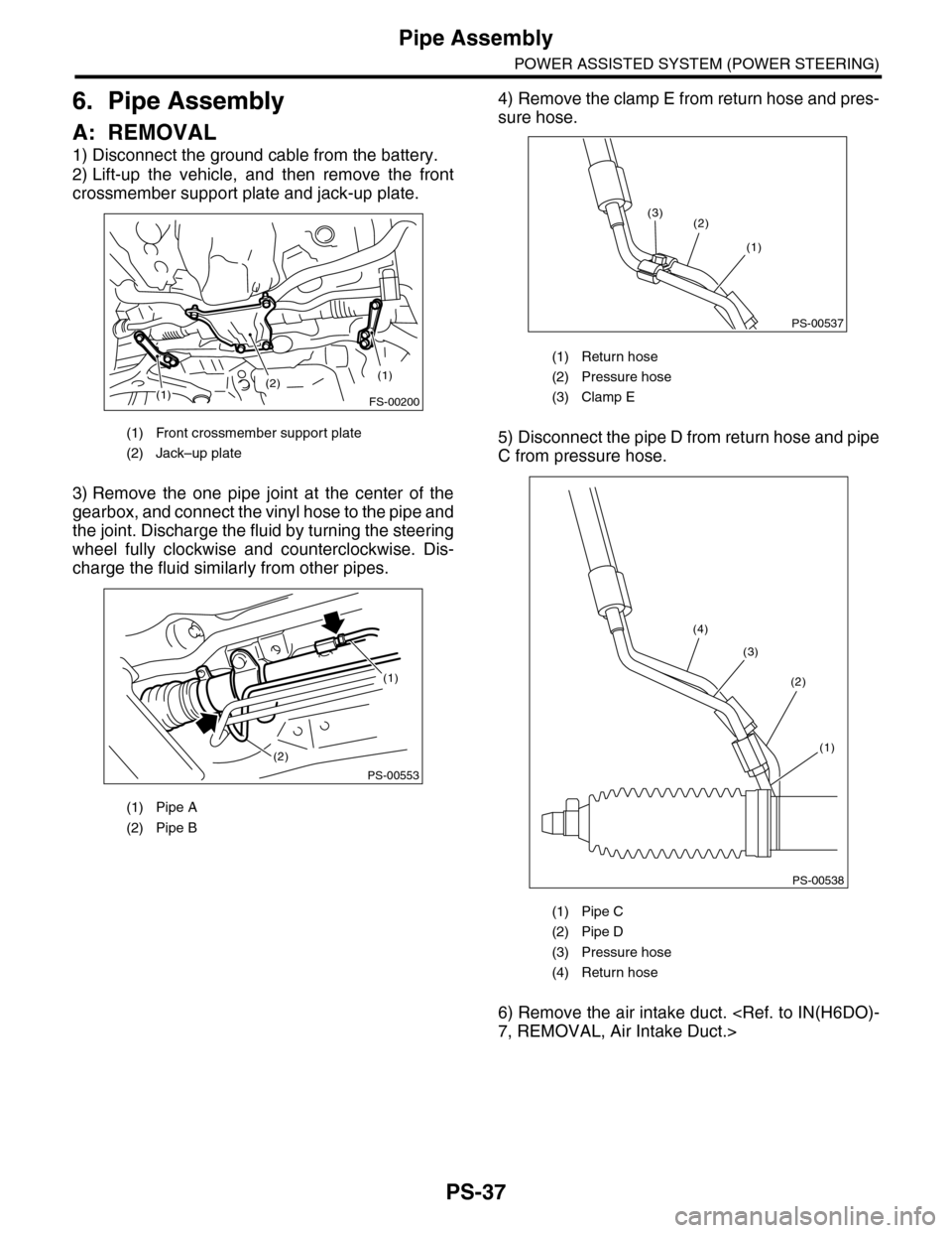
1) Disconnect the ground cable from the battery.
2) Lift-up the vehicle, and then remove the front
crossmember support plate and jack-up plate.
3) Remove the one pipe joint at the center of the
gearbox, and connect the vinyl hose to the pipe and
the joint. Discharge the fluid by turning the steering
wheel fully clockwise and counterclockwise. Dis-
charge the fluid similarly from other pipes.
4) Remove the clamp E from return hose and pres-
sure hose.
5) Disconnect the pipe D from return hose and pipe
C from pressure hose.
6) Remove the air intake duct.
(1) Front crossmember support plate
(2) Jack–up plate
(1) Pipe A
(2) Pipe B
(2)(1)
(1)
FS-00200
(2)
PS-00553
(1)
(1) Return hose
(2) Pressure hose
(3) Clamp E
(1) Pipe C
(2) Pipe D
(3) Pressure hose
(4) Return hose
PS-00537
(3)
(1)
(2)
PS-00538
(4)
(3)
(2)
(1)
Page 918 of 2453
PS-38
Pipe Assembly
POWER ASSISTED SYSTEM (POWER STEERING)
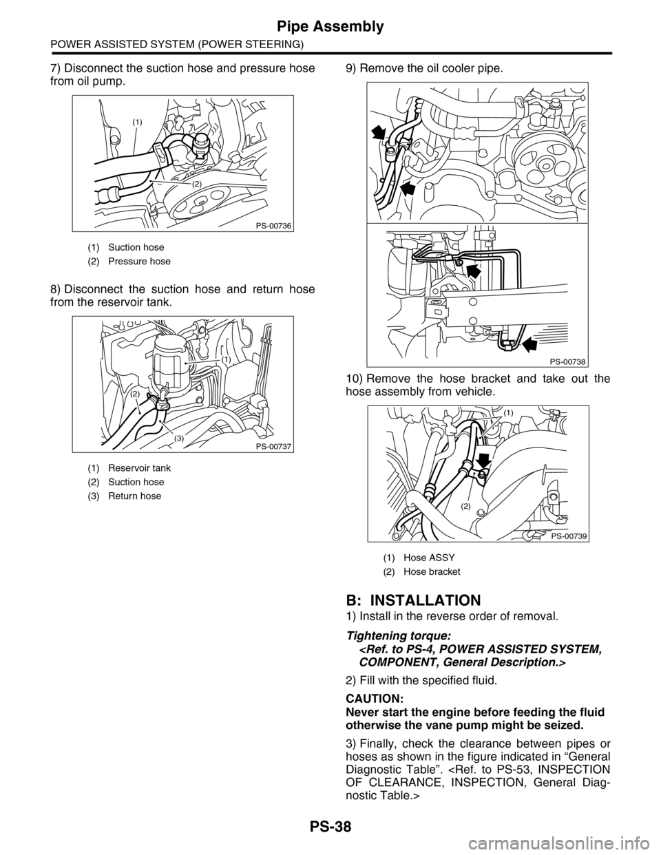
7) Disconnect the suction hose and pressure hose
from oil pump.
8) Disconnect the suction hose and return hose
from the reservoir tank.
9) Remove the oil cooler pipe.
10) Remove the hose bracket and take out the
hose assembly from vehicle.
B: INSTALLATION
1) Install in the reverse order of removal.
Tightening torque:
2) Fill with the specified fluid.
CAUTION:
Never start the engine before feeding the fluid
otherwise the vane pump might be seized.
3) Finally, check the clearance between pipes or
hoses as shown in the figure indicated in “General
Diagnostic Table”.
nostic Table.>
(1) Suction hose
(2) Pressure hose
(1) Reservoir tank
(2) Suction hose
(3) Return hose
PS-00736
(1)
(2)
PS-00737(3)
(2)
(1)
(1) Hose ASSY
(2) Hose bracket
PS-00738
PS-00739
(2)
(1)
Page 919 of 2453
PS-39
Pipe Assembly
POWER ASSISTED SYSTEM (POWER STEERING)
C: INSPECTION
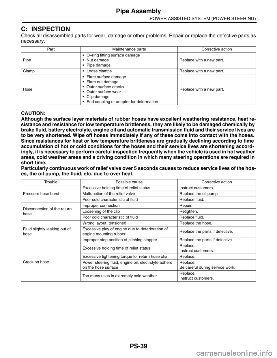
Check all disassembled parts for wear, damage or other problems. Repair or replace the defective parts as
necessary.
CAUTION:
Although the surface layer materials of rubber hoses have excellent weathering resistance, heat re-
sistance and resistance for low temperature brittleness, they are likely to be damaged chemically by
brake fluid, battery electrolyte, engine oil and automatic transmission fluid and their service lives are
to be very shortened. Wipe off hoses immediately if any of these come into contact with the hoses.
Since resistances for heat or low temperature brittleness are gradually declining according to time
accumulation of hot or cold conditions for the hoses and their service lives are shortening accord-
ingly, it is necessary to perform careful inspection frequently when the vehicle is used in hot weather
areas, cold weather areas and a driving condition in which many steering operations are required in
short time.
Particularly continuous work of relief valve over 5 seconds causes to reduce service lives of the hos-
es, the oil pump, the fluid, etc. due to over heat.
Par t Maintenance par ts Corrective action
Pipe
•O–ring fitting surface damage
•Nut damage
•Pipe damage
Replace with a new part.
Clamp • Loose clamps Replace with a new part.
Hose
•Flare surface damage
•Flare nut damage
•Outer surface cracks
•Outer surface wear
•Clip damage
•End coupling or adapter for deformation
Replace with a new part.
Tr o u b l e P o s s i b l e c a u s e C o r r e c t i v e a c t i o n
Pressure hose burst
Excessive holding time of relief status Instruct customers.
Malfunction of the relief valve Replace the oil pump.
Poor cold character istic of fluid R eplace fluid.
Disconnection of the return
hose
Improper connection Repair.
Loosening of the clip Retighten.
Poor cold character istic of fluid R eplace fluid.
Fluid slightly leaking out of
hose
Wrong layout, tensioned Replace the hose.
Excessive play of engine due to deterioration of
engine mounting rubberReplace the parts if defective.
Improper stop position of pitching stopper Replace the parts if defective.
Crack on hose
Excessive holding time of relief statusReplace.
Instruct customers.
Excessive tightening torque for return hose clip Replace.
Power steer ing fluid, engine oil, electrolyte adhere
on the hose surface
Replace.
Be careful during service work.
To o m a n y u s e s i n e x t r e m e l y c o l d w e a t h e rReplace.
Instruct customers.
Page 920 of 2453
PS-40
Pipe Assembly
POWER ASSISTED SYSTEM (POWER STEERING)
NOTE:
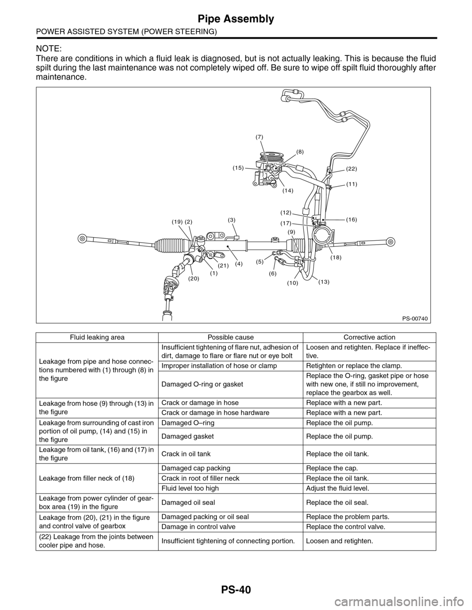
There are conditions in which a fluid leak is diagnosed, but is not actually leaking. This is because the fluid
spilt during the last maintenance was not completely wiped off. Be sure to wipe off spilt fluid thoroughly after
maintenance.
Fluid leaking area Possible cause Corrective action
Leakage from pipe and hose connec-
tions numbered with (1) through (8) in
the figure
Insufficient tightening of flare nut, adhesion of
dirt, damage to flare or flare nut or eye bolt
Loosen and retighten. Replace if ineffec-
tive.
Improper installation of hose or clamp Retighten or replace the clamp.
Damaged O-ring or gasket
Replace the O-ring, gasket pipe or hose
with new one, if still no improvement,
replace the gearbox as well.
Leakage from hose (9) through (13) in
the figure
Crack or damage in hose Replace with a new part.
Crack or damage in hose hardware Replace with a new part.
Leakage from surrounding of cast iron
portion of oil pump, (14) and (15) in
the figure
Damaged O–ring Replace the oil pump.
Damaged gasket Replace the oil pump.
Leakage from oil tank, (16) and (17) in
the figureCrack in oil tank Replace the oil tank.
Leakage from filler neck of (18)
Damaged cap packing Replace the cap.
Crack in root of filler neck Replace the oil tank.
Fluid level too high Adjust the fluid level.
Leakage from power cylinder of gear-
box area (19) in the figureDamaged oil seal Replace the oil seal.
Leakage from (20), (21) in the figure
and control valve of gearbox
Damaged packing or oil seal Replace the problem parts.
Damage in control valve Replace the control valve.
(22) Leakage from the joints between
cooler pipe and hose.Insufficient tightening of connecting portion. Loosen and retighten.
PS-00740
(1)
(19)
(4)
(2)
(7)
(20)
(3)
(21)
(15)
(8)
(14)
(12)
(17)
(9)
(5)
(6)
(10)(13)
(18)
(16)
(11)
(22)