SUZUKI GRAND VITARA 1999 2.G Owners Manual
Manufacturer: SUZUKI, Model Year: 1999, Model line: GRAND VITARA, Model: SUZUKI GRAND VITARA 1999 2.GPages: 656, PDF Size: 14.31 MB
Page 311 of 656
6A2-24 ENGINE MECHANICAL (H27 ENGINE)
ASSEMBLY
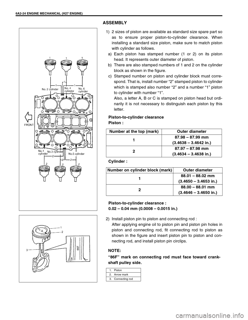
1) 2 sizes of piston are available as standard size spare part so
as to ensure proper piston-to-cylinder clearance. When
installing a standard size piston, make sure to match piston
with cylinder as follows.
a) Each piston has stamped number (1 or 2) on its piston
head. It represents outer diameter of piston.
b) There are also stamped numbers of 1 and 2 on the cylinder
block as shown in the figure.
c) Stamped number on piston and cylinder block must corre-
spond. That is, install number “2” stamped piston to cylinder
which is stamped also number “2” and a number “1” piston
to cylinder with number “1”.
Also, a letter A, B or C is stamped on piston head but ordi-
narily it is not necessary to distinguish each piston by this
letter.
Piston-to-cylinder clearance
Piston :
Cylinder :
Piston-to-cylinder clearance :
0.02 – 0.04 mm (0.0008 – 0.0015 in.)
2) Install piston pin to piston and connecting rod :
After applying engine oil to piston pin and piston pin holes in
piston and connecting rod, fit connecting rod to piston as
shown in the figure and insert piston pin to piston and con-
necting rod, and install piston pin circlips. Number at the top (mark) Outer diameter
187.98 – 87.99 mm
(3.4638 – 3.4642 in.)
287.97 – 87.98 mm
(3.4634 – 3.4638 in.)
Number on cylinder block (mark) Outer diameter
188.01 – 88.02 mm
(3.4650 – 3.4653 in.)
288.00 – 88.01 mm
(3.4646 – 3.4650 in.)
NOTE:
“86F” mark on connecting rod must face toward crank-
shaft pulley side.
1. Piston
2. Arrow mark
3. Connecting rod
Page 312 of 656
ENGINE MECHANICAL (H27 ENGINE) 6A2-25
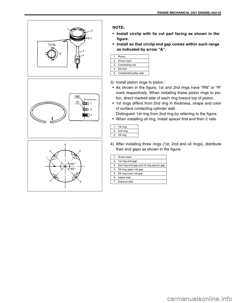
3) Install piston rings to piston :
•As shown in the figure, 1st and 2nd rings have “RN” or “R”
mark respectively. When installing these piston rings to pis-
ton, direct marked side of each ring toward top of piston.
•1st rings differs from 2nd ring in thickness, shape and color
of surface contacting cylinder wall.
Distinguish 1st ring from 2nd ring by referring to the figure.
•When installing oil ring, install spacer first and then 2 rails.
4) After installing three rings (1st, 2nd and oil rings), distribute
their end gaps as shown in the figure. NOTE:
Install circlip with its cut part facing as shown in the
figure.
Install so that circlip end gap comes within such range
as indicated by arrow “A”.
1. Piston
2. Arrow mark
3. Connecting rod
4. Oil hole
5. Crankshaft pulley side
1. 1st ring
2. 2nd ring
3. Oil ring
1. Arrow mark
2. 1st ring end gap
3. 2nd ring end gap and oil ring spacer gap
4. Oil ring upper rail gap
5. Oil ring lower rail gap
6. Intake side
7. Exhaust side
Page 313 of 656
6A2-26 ENGINE MECHANICAL (H27 ENGINE)
Unit Repair Overhaul
Engine Assembly
REMOVAL
1) Release fuel pressure in fuel feed line. Refer to “FUEL
PRESSURE RELIEF PROCEDURE” in Section 6.
2) Disconnect negative (–) cable at battery.
3) Remove engine hood.
4) Drain engine oil.
5) Drain coolant.
6) Remove radiator, radiator fan shroud, cooling fan and radia-
tor reservoir. Refer to “COOLING FAN AND FAN CLUTCH”
and “RADIATOR” in Section 6B.
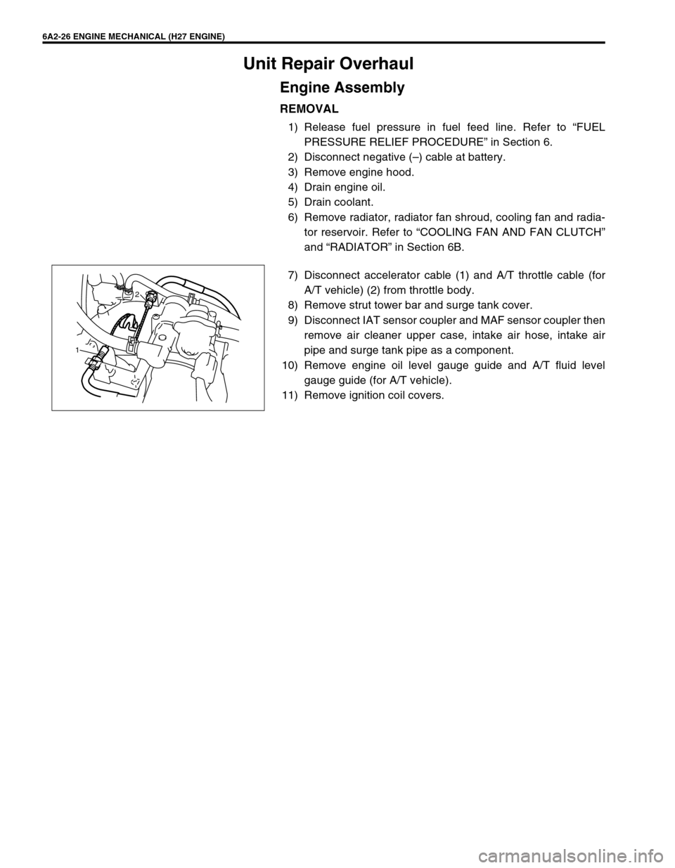
7) Disconnect accelerator cable (1) and A/T throttle cable (for
A/T vehicle) (2) from throttle body.
8) Remove strut tower bar and surge tank cover.
9) Disconnect IAT sensor coupler and MAF sensor coupler then
remove air cleaner upper case, intake air hose, intake air
pipe and surge tank pipe as a component.
10) Remove engine oil level gauge guide and A/T fluid level
gauge guide (for A/T vehicle).
11) Remove ignition coil covers.
12
Page 314 of 656
ENGINE MECHANICAL (H27 ENGINE) 6A2-27
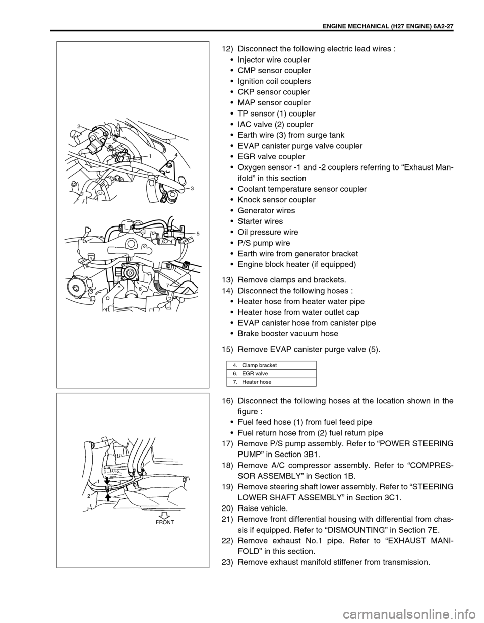
12) Disconnect the following electric lead wires :
•Injector wire coupler
•CMP sensor coupler
•Ignition coil couplers
•CKP sensor coupler
•MAP sensor coupler
•TP sensor (1) coupler
•IAC valve (2) coupler
•Earth wire (3) from surge tank
•EVAP canister purge valve coupler
•EGR valve coupler
•Oxygen sensor -1 and -2 couplers referring to “Exhaust Man-
ifold” in this section
•Coolant temperature sensor coupler
•Knock sensor coupler
•Generator wires
•Starter wires
•Oil pressure wire
•P/S pump wire
•Earth wire from generator bracket
•Engine block heater (if equipped)
13) Remove clamps and brackets.
14) Disconnect the following hoses :
•Heater hose from heater water pipe
•Heater hose from water outlet cap
•EVAP canister hose from canister pipe
•Brake booster vacuum hose
15) Remove EVAP canister purge valve (5).
16) Disconnect the following hoses at the location shown in the
figure :
•Fuel feed hose (1) from fuel feed pipe
•Fuel return hose from (2) fuel return pipe
17) Remove P/S pump assembly. Refer to “POWER STEERING
PUMP” in Section 3B1.
18) Remove A/C compressor assembly. Refer to “COMPRES-
SOR ASSEMBLY” in Section 1B.
19) Remove steering shaft lower assembly. Refer to “STEERING
LOWER SHAFT ASSEMBLY” in Section 3C1.
20) Raise vehicle.
21) Remove front differential housing with differential from chas-
sis if equipped. Refer to “DISMOUNTING” in Section 7E.
22) Remove exhaust No.1 pipe. Refer to “EXHAUST MANI-
FOLD” in this section.
23) Remove exhaust manifold stiffener from transmission.
4. Clamp bracket
6. EGR valve
7. Heater hose
2
14
3
75
6
Page 315 of 656
6A2-28 ENGINE MECHANICAL (H27 ENGINE)
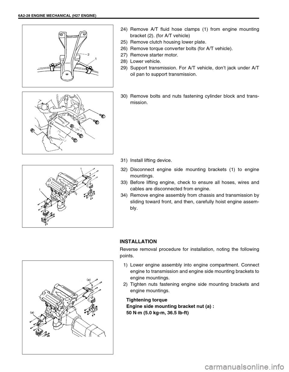
24) Remove A/T fluid hose clamps (1) from engine mounting
bracket (2). (for A/T vehicle)
25) Remove clutch housing lower plate.
26) Remove torque converter bolts (for A/T vehicle).
27) Remove starter motor.
28) Lower vehicle.
29) Support transmission. For A/T vehicle, don’t jack under A/T
oil pan to support transmission.
30) Remove bolts and nuts fastening cylinder block and trans-
mission.
31) Install lifting device.
32) Disconnect engine side mounting brackets (1) to engine
mountings.
33) Before lifting engine, check to ensure all hoses, wires and
cables are disconnected from engine.
34) Remove engine assembly from chassis and transmission by
sliding toward front, and then, carefully hoist engine assem-
bly.
INSTALLATION
Reverse removal procedure for installation, noting the following
points.
1) Lower engine assembly into engine compartment. Connect
engine to transmission and engine side mounting brackets to
engine mountings.
2) Tighten nuts fastening engine side mounting brackets and
engine mountings.
Tightening torque
Engine side mounting bracket nut (a) :
50 N·m (5.0 kg-m, 36.5 lb-ft)
Page 316 of 656
ENGINE MECHANICAL (H27 ENGINE) 6A2-29
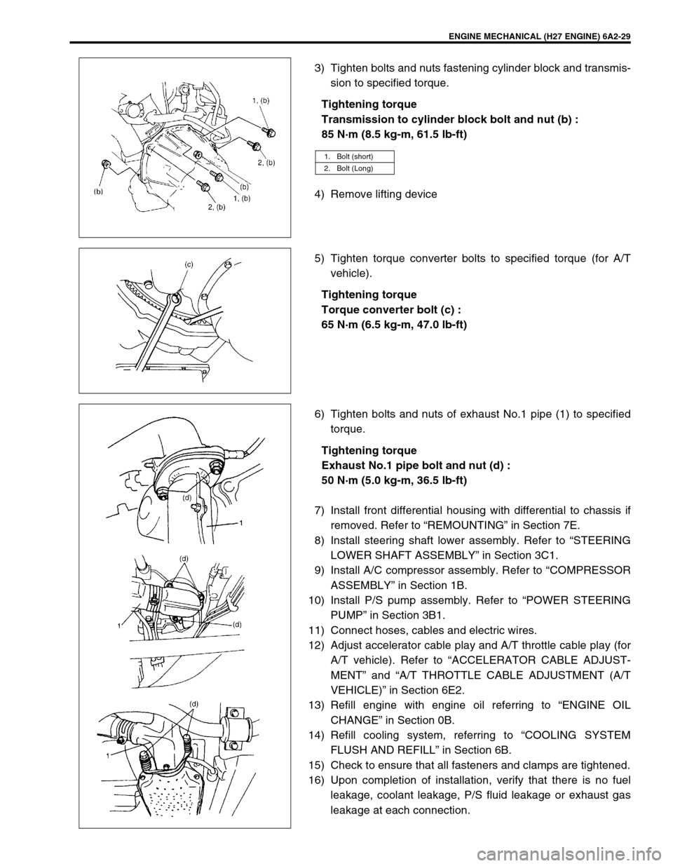
3) Tighten bolts and nuts fastening cylinder block and transmis-
sion to specified torque.
Tightening torque
Transmission to cylinder block bolt and nut (b) :
85 N·m (8.5 kg-m, 61.5 lb-ft)
4) Remove lifting device
5) Tighten torque converter bolts to specified torque (for A/T
vehicle).
Tightening torque
Torque converter bolt (c) :
65 N·m (6.5 kg-m, 47.0 lb-ft)
6) Tighten bolts and nuts of exhaust No.1 pipe (1) to specified
torque.
Tightening torque
Exhaust No.1 pipe bolt and nut (d) :
50 N·m (5.0 kg-m, 36.5 lb-ft)
7) Install front differential housing with differential to chassis if
removed. Refer to “REMOUNTING” in Section 7E.
8) Install steering shaft lower assembly. Refer to “STEERING
LOWER SHAFT ASSEMBLY” in Section 3C1.
9) Install A/C compressor assembly. Refer to “COMPRESSOR
ASSEMBLY” in Section 1B.
10) Install P/S pump assembly. Refer to “POWER STEERING
PUMP” in Section 3B1.
11) Connect hoses, cables and electric wires.
12) Adjust accelerator cable play and A/T throttle cable play (for
A/T vehicle). Refer to “ACCELERATOR CABLE ADJUST-
MENT” and “A/T THROTTLE CABLE ADJUSTMENT (A/T
VEHICLE)” in Section 6E2.
13) Refill engine with engine oil referring to “ENGINE OIL
CHANGE” in Section 0B.
14) Refill cooling system, referring to “COOLING SYSTEM
FLUSH AND REFILL” in Section 6B.
15) Check to ensure that all fasteners and clamps are tightened.
16) Upon completion of installation, verify that there is no fuel
leakage, coolant leakage, P/S fluid leakage or exhaust gas
leakage at each connection.
1. Bolt (short)
2. Bolt (Long)
Page 317 of 656
![SUZUKI GRAND VITARA 1999 2.G Owners Manual 6A2-30 ENGINE MECHANICAL (H27 ENGINE)
Main Bearings, Crankshaft and Cylinder Block
1. Cylinder block 6. Rear oil seal 11. O-ring [A]: Sealant application amount
2. Lower crankcase :
Apply sealant 9900 SUZUKI GRAND VITARA 1999 2.G Owners Manual 6A2-30 ENGINE MECHANICAL (H27 ENGINE)
Main Bearings, Crankshaft and Cylinder Block
1. Cylinder block 6. Rear oil seal 11. O-ring [A]: Sealant application amount
2. Lower crankcase :
Apply sealant 9900](/img/20/7583/w960_7583-316.png)
6A2-30 ENGINE MECHANICAL (H27 ENGINE)
Main Bearings, Crankshaft and Cylinder Block
1. Cylinder block 6. Rear oil seal 11. O-ring [A]: Sealant application amount
2. Lower crankcase :
Apply sealant 99000-31150 to lower
crankcase mating surface.7. Flywheel (M/T) Drive plate
(A/T)12. Clutch housing plate Tightening Torque
3. Crankshaft 8. Water pump 13. Cap bolt Do not reuse
4. Main bearing 9. O-ring 14. Lower crankcase bolt Apply engine oil to sliding
surface of each parts.
5. Thrust bearing :
Set bearing facing grooved side to
crank weds.10. Timing chain oil jet 15. Knock sensor“a”: Width 3 mm (0.12 in.)
“b”: Height 2 mm (0.08 in.)
Page 318 of 656
ENGINE MECHANICAL (H27 ENGINE) 6A2-31
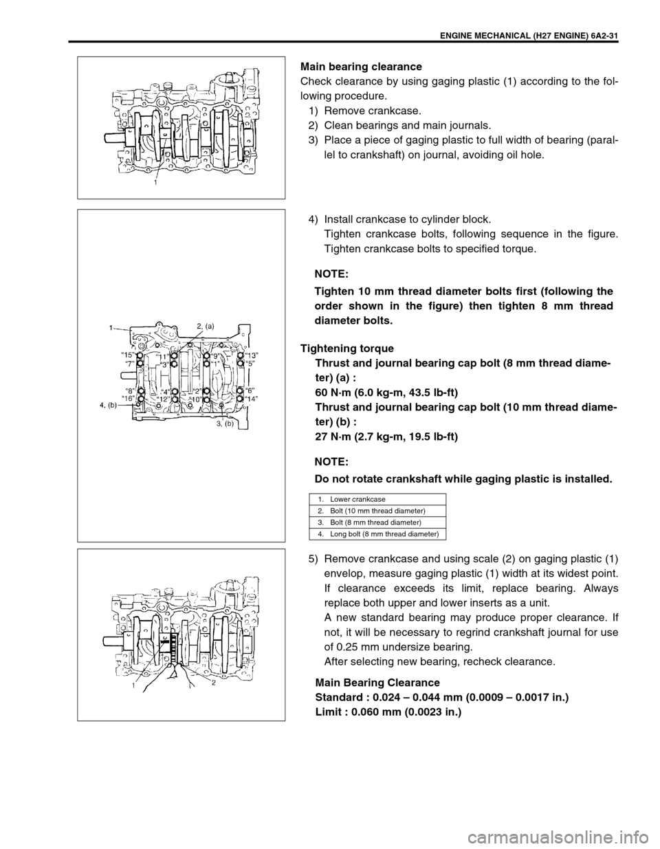
Main bearing clearance
Check clearance by using gaging plastic (1) according to the fol-
lowing procedure.
1) Remove crankcase.
2) Clean bearings and main journals.
3) Place a piece of gaging plastic to full width of bearing (paral-
lel to crankshaft) on journal, avoiding oil hole.
4) Install crankcase to cylinder block.
Tighten crankcase bolts, following sequence in the figure.
Tighten crankcase bolts to specified torque.
Tightening torque
Thrust and journal bearing cap bolt (8 mm thread diame-
ter) (a) :
60 N·m (6.0 kg-m, 43.5 lb-ft)
Thrust and journal bearing cap bolt (10 mm thread diame-
ter) (b) :
27 N·m (2.7 kg-m, 19.5 lb-ft)
5) Remove crankcase and using scale (2) on gaging plastic (1)
envelop, measure gaging plastic (1) width at its widest point.
If clearance exceeds its limit, replace bearing. Always
replace both upper and lower inserts as a unit.
A new standard bearing may produce proper clearance. If
not, it will be necessary to regrind crankshaft journal for use
of 0.25 mm undersize bearing.
After selecting new bearing, recheck clearance.
Main Bearing Clearance
Standard : 0.024 – 0.044 mm (0.0009 – 0.0017 in.)
Limit : 0.060 mm (0.0023 in.)
NOTE:
Tighten 10 mm thread diameter bolts first (following the
order shown in the figure) then tighten 8 mm thread
diameter bolts.
NOTE:
Do not rotate crankshaft while gaging plastic is installed.
1. Lower crankcase
2. Bolt (10 mm thread diameter)
3. Bolt (8 mm thread diameter)
4. Long bolt (8 mm thread diameter)
Page 319 of 656
6A2-32 ENGINE MECHANICAL (H27 ENGINE)
Selection of main bearings
•STANDARD BEARING :
If bearing is in malcondition, or bearing clearance is out of
specification, select a new standard bearing according to the
following procedure and install it.
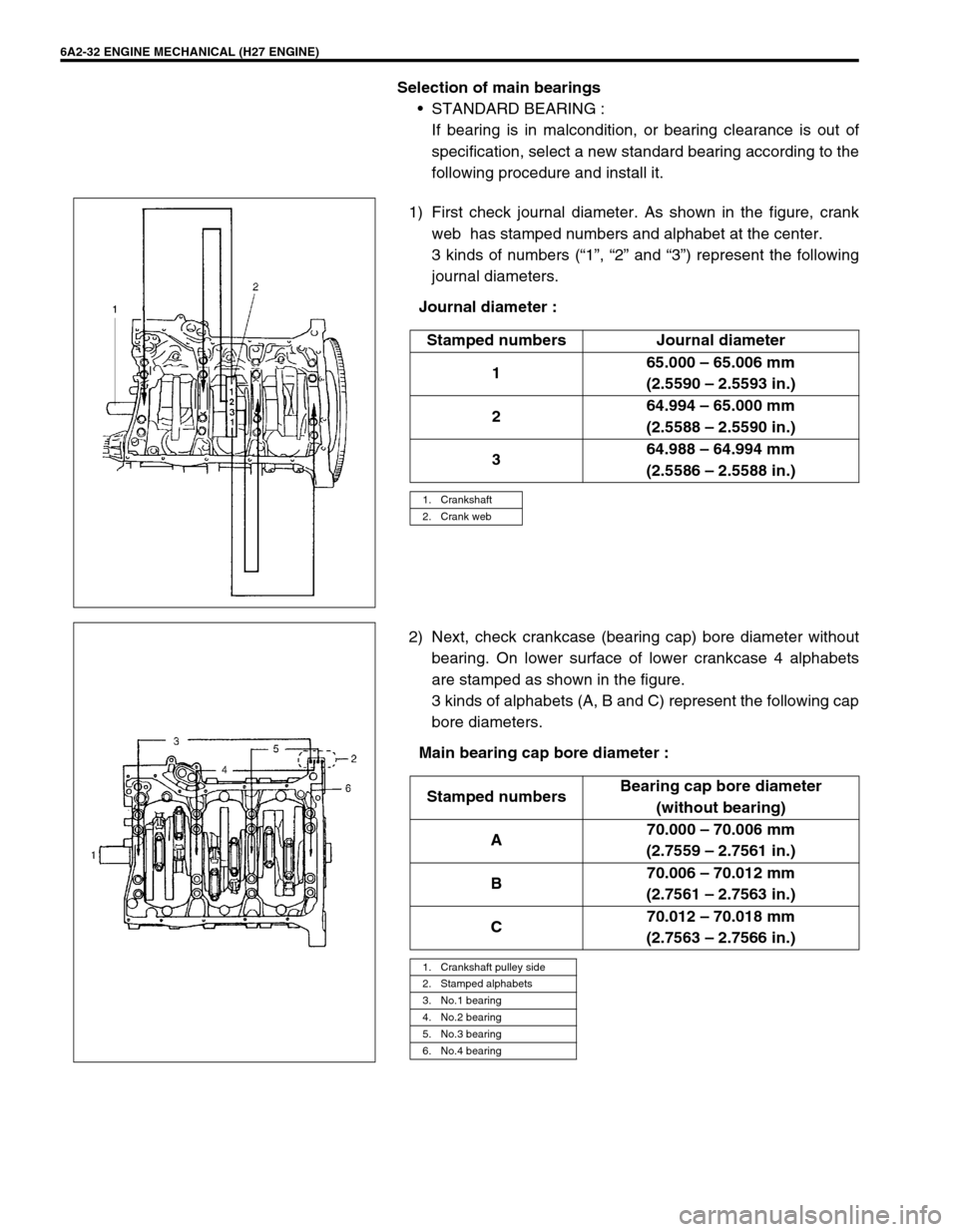
1) First check journal diameter. As shown in the figure, crank
web has stamped numbers and alphabet at the center.
3 kinds of numbers (“1”, “2” and “3”) represent the following
journal diameters.
Journal diameter :
2) Next, check crankcase (bearing cap) bore diameter without
bearing. On lower surface of lower crankcase 4 alphabets
are stamped as shown in the figure.
3 kinds of alphabets (A, B and C) represent the following cap
bore diameters.
Main bearing cap bore diameter :Stamped numbers Journal diameter
165.000 – 65.006 mm
(2.5590 – 2.5593 in.)
264.994 – 65.000 mm
(2.5588 – 2.5590 in.)
364.988 – 64.994 mm
(2.5586 – 2.5588 in.)
1. Crankshaft
2. Crank web
Stamped numbersBearing cap bore diameter
(without bearing)
A70.000 – 70.006 mm
(2.7559 – 2.7561 in.)
B70.006 – 70.012 mm
(2.7561 – 2.7563 in.)
C70.012 – 70.018 mm
(2.7563 – 2.7566 in.)
1. Crankshaft pulley side
2. Stamped alphabets
3. No.1 bearing
4. No.2 bearing
5. No.3 bearing
6. No.4 bearing
Page 320 of 656
ENGINE MECHANICAL (H27 ENGINE) 6A2-33
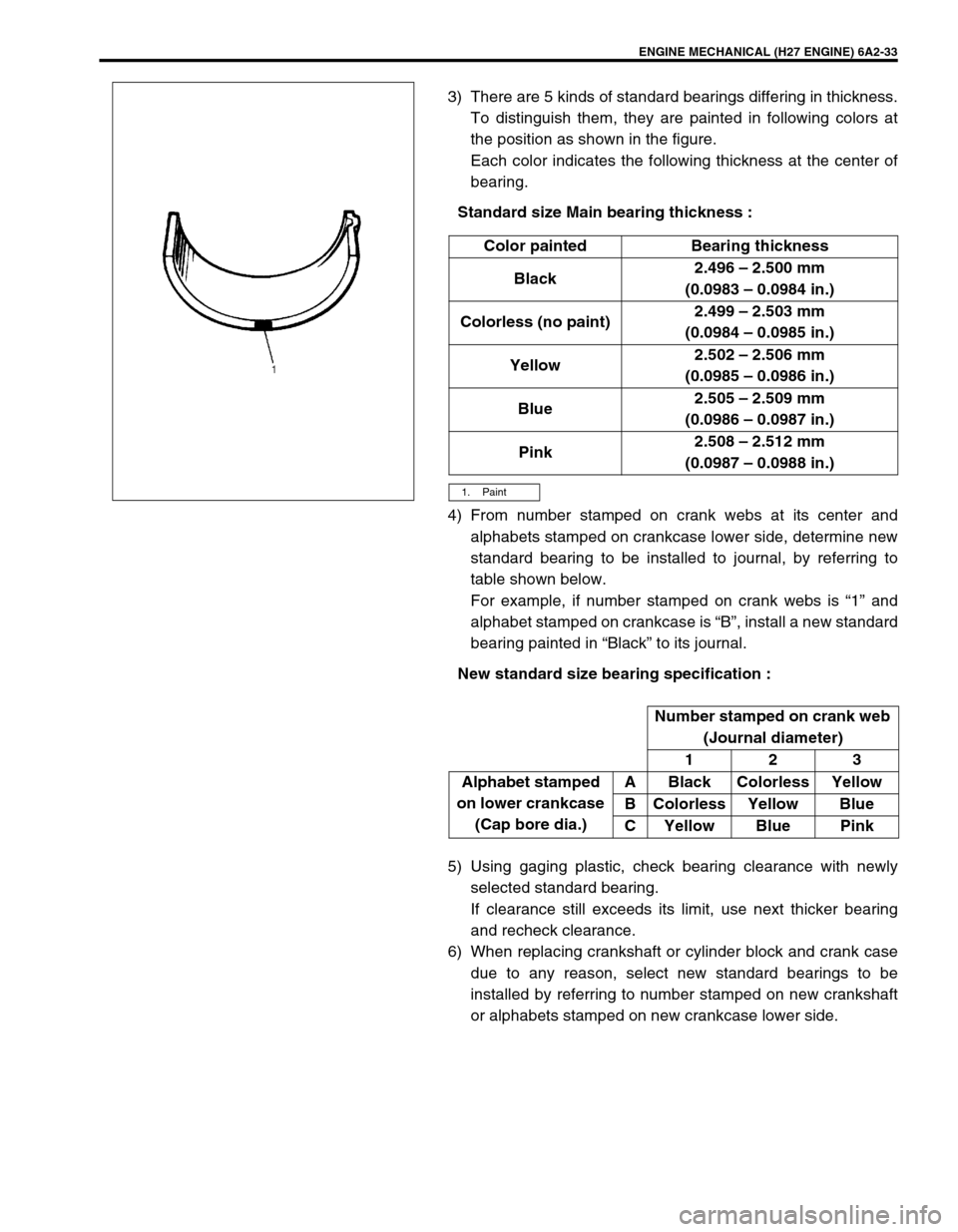
3) There are 5 kinds of standard bearings differing in thickness.
To distinguish them, they are painted in following colors at
the position as shown in the figure.
Each color indicates the following thickness at the center of
bearing.
Standard size Main bearing thickness :
4) From number stamped on crank webs at its center and
alphabets stamped on crankcase lower side, determine new
standard bearing to be installed to journal, by referring to
table shown below.
For example, if number stamped on crank webs is “1” and
alphabet stamped on crankcase is “B”, install a new standard
bearing painted in “Black” to its journal.
New standard size bearing specification :
5) Using gaging plastic, check bearing clearance with newly
selected standard bearing.
If clearance still exceeds its limit, use next thicker bearing
and recheck clearance.
6) When replacing crankshaft or cylinder block and crank case
due to any reason, select new standard bearings to be
installed by referring to number stamped on new crankshaft
or alphabets stamped on new crankcase lower side.Color painted Bearing thickness
Black2.496 – 2.500 mm
(0.0983 – 0.0984 in.)
Colorless (no paint)2.499 – 2.503 mm
(0.0984 – 0.0985 in.)
Yellow2.502 – 2.506 mm
(0.0985 – 0.0986 in.)
Blue2.505 – 2.509 mm
(0.0986 – 0.0987 in.)
Pink2.508 – 2.512 mm
(0.0987 – 0.0988 in.)
1. Paint
Number stamped on crank web
(Journal diameter)
123
Alphabet stamped
on lower crankcase
(Cap bore dia.)A Black Colorless Yellow
B Colorless Yellow Blue
C Yellow Blue Pink