SUZUKI SWIFT 2000 1.G Transmission Service Workshop Manual
Manufacturer: SUZUKI, Model Year: 2000, Model line: SWIFT, Model: SUZUKI SWIFT 2000 1.GPages: 447, PDF Size: 10.54 MB
Page 101 of 447

AUTOMATIC TRANSMISSION (4 A/T) 7B-59
INSTALLATION
1) Using flat tip screwdriver, turn transmission range sensor to
have the match marks (1) line up (transmission range sensor
“N” range).
2) Turn selector lever (1) to “N” range (to have the automatic
transmission to “N” range).
3) Install transmission range sensor (1) to transmission case.
Tightening torque
Transmission range sensor bolt
(a) : 18 N·m (1.8 kg-m, 13.0 lb-ft)
4) Move selector lever in cabin to each range and check the
continuity of each terminal of transmission range sensor
referring to “INSPECTION”.
5) Connect transmission range sensor coupler.
6) Check that the engine can only be started in “N” and “P”
range, but can not in “D”, “2”, “L” or “R” range. Also, check
that backup lamp come ON at “R” range.
Page 102 of 447

7B-60 AUTOMATIC TRANSMISSION (4 A/T)
SELECTOR CABLE
REMOVAL
1) Remove parking brake lever cover.
2) Remove console box.
3) Disconnect selector cable from selector lever and then
detach from bracket.
4) Remove clip and disconnect selector cable from transmis-
sion.
5) Remove selector housing from dash panel.
INSTALLATION
Install selector cable by reversing removal procedure.
The important steps in installation are as follows.
Apply grease to pin and cable joint.
Tighten bolts and nut in upper figure to specified torque.
Adjusting procedure is as follows.
1. Selector lever assembly 6. Clip
2. Selector cable 7. Selector housing bolt
3. Selector housing 8. Shift control lever pin
: Apply lithium grease 99000-25010 to all around pin (0.15 g)
4. Cable bracket 9. Selector lever pin
: Apply lithium grease 99000-25010 to all around pin (0.15 g)
5. Shift control lever Tightening torque
Page 103 of 447

AUTOMATIC TRANSMISSION (4 A/T) 7B-61
ADJUSTMENT
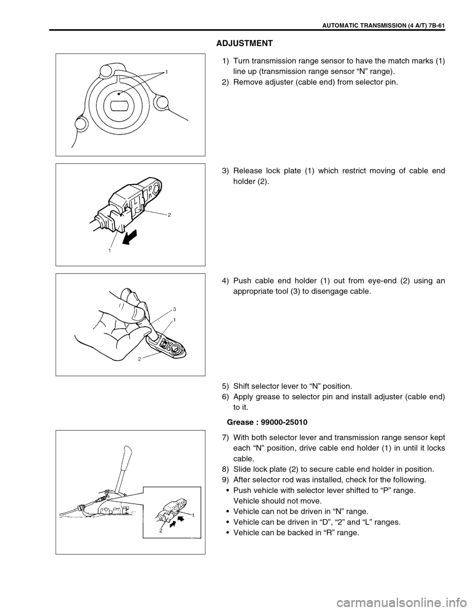
1) Turn transmission range sensor to have the match marks (1)
line up (transmission range sensor “N” range).
2) Remove adjuster (cable end) from selector pin.
3) Release lock plate (1) which restrict moving of cable end
holder (2).
4) Push cable end holder (1) out from eye-end (2) using an
appropriate tool (3) to disengage cable.
5) Shift selector lever to “N” position.
6) Apply grease to selector pin and install adjuster (cable end)
to it.
Grease : 99000-25010
7) With both selector lever and transmission range sensor kept
each “N” position, drive cable end holder (1) in until it locks
cable.
8) Slide lock plate (2) to secure cable end holder in position.
9) After selector rod was installed, check for the following.
Push vehicle with selector lever shifted to “P” range.
Vehicle should not move.
Vehicle can not be driven in “N” range.
Vehicle can be driven in “D”, “2” and “L” ranges.
Vehicle can be backed in “R” range.
Page 104 of 447

7B-62 AUTOMATIC TRANSMISSION (4 A/T)
OUTPUT SHAFT SPEED SENSOR (A/T VSS)
INSPECTION
1) Disconnect negative cable at battery.
2) Disconnect output shaft speed sensor – input shaft speed
sensor coupler (1).
3) Check resistance between output shaft speed sensor termi-
nals (2).
Output shaft speed sensor resistance
Standard : 160 – 200
Ω
ΩΩ Ω at 20°C (68°F)
REMOVAL
1) Disconnect negative cable at battery.
2) Disconnect output shaft speed sensor – input shaft speed
sensor coupler.
3) Remove output shaft speed sensor (1) by removing its bolt.
INSTALLATION
1) Apply A/T fluid to output shaft speed sensor o-ring.
2) Install output shaft speed sensor (1) to A/T case and tighten
bolt to specified torque.
Tightening torque
Output shaft speed sensor bolt
(a) : 8 N·m (0.8 kg-m, 6.0 lb-ft)
3) Connect output shaft speed sensor – input shaft speed sen-
sor coupler.
4) Connect negative cable to battery.
Page 105 of 447

AUTOMATIC TRANSMISSION (4 A/T) 7B-63
INPUT SHAFT SPEED SENSOR
INSPECTION
1) Disconnect negative cable at battery.
2) Disconnect output shaft speed sensor – input shaft speed
sensor coupler (1).
3) Check resistance between input shaft speed sensor termi-
nals (2).
Input shaft speed sensor resistance
Standard : 160 – 200
Ω
ΩΩ Ω at 20°C (68°F)
REMOVAL
1) Disconnect negative cable at battery.
2) Disconnect output shaft speed sensor – input shaft speed
sensor coupler.
3) Remove input shaft speed sensor (1) by removing its bolt.
INSTALLATION
1) Apply A/T fluid to input shaft speed sensor O-ring.
2) Install input shaft speed sensor (1) to A/T case and tighten
bolt to specified torque.
Tightening torque
Input shaft speed sensor bolt
(b) : 8 N·m (0.8 kg-m, 6.0 lb-ft)
3) Connect output shaft speed sensor – input shaft speed sen-
sor coupler.
4) Connect negative cable to battery.
VEHICLE SPEED SENSOR (VSS)
Refer to Section 6E for removal, installation and inspection.
THROTTLE POSITION SENSOR
INSPECTION
Check throttle position sensor referring to Section 6E.
Page 106 of 447

7B-64 AUTOMATIC TRANSMISSION (4 A/T)
ENGINE COOLANT TEMP. (ECT) SENSOR
INSPECTION
Check engine coolant temp. sensor referring to Section 6E.
DROPPING RESISTOR
REMOVAL/INSTALLATION
Refer to the figure for removal/installation.
Tightening torque
Dropping resistor bolts
(a) : 20 N·m (2.0 kg-m, 14.5 lb-ft)
INSPECTION
Measure resistance between each resistor terminals.
Dropping resistor resistance
CIRCUIT RESISTANCE
Shift solenoid -C (No.3) 6.5 – 8.5
Ω
ΩΩ Ω
Shift solenoid -D (No.4) 6.5 – 8.5
Ω
ΩΩ Ω
Shift solenoid -E (No.5) 6.5 – 8.5
Ω
ΩΩ Ω
1. Resistor terminal for shift solenoid -C Circuit
2. Resistor terminal for shift solenoid -D Circuit
3. Resistor terminal for shift solenoid -E Circuit
Page 107 of 447

AUTOMATIC TRANSMISSION (4 A/T) 7B-65
O/D OFF SWITCH
INSPECTION
1) Remove console box.
2) Disconnect O/D off switch coupler (1).
3) Check continuity between O/D off switch terminals.
O/D OFF switch specification
SHIFT SOLENOID VALVES AND TRANSMIS-
SION TEMPERATURE SENSOR
REMOVAL
1) Disconnect negative cable at battery.
2) Drain A/T fluid.
3) Remove A/T oil pan (1).
4) Disconnect transmission temp. sensor coupler (3).
5) Remove A/T oil strainer (2) and transmission temp. sensor
(1). O/D off switch ON OFF
Continuity Continuity No continuity
2. O/D off switch ON
3. O/D off switch OFF
Page 108 of 447

7B-66 AUTOMATIC TRANSMISSION (4 A/T)
6) Disconnect shift solenoid couplers.
7) Remove shift solenoid valves.
SHIFT SOLENOID VALVES
INSPECTION
Resistance Check
Shift solenoid A (No.1), B (No.2) and lock-up solenoid
Resistance between terminal and solenoid body
Standard : 10.5 – 15.5
Ω
ΩΩ Ω
Shift solenoid C (No.3), D (No.4) or E (No.5)
Resistance between terminal and solenoid body
Standard : 2.5 – 3.5
Ω
ΩΩ Ω
Operation check
When solenoids is connected to the battery as shown in figure,
check that the solenoid actuates with a click sound.
TRANSMISSION TEMPERATURE SENSOR
INSPECTION
Warm up transmission temp. sensor. Thus make sure its resis-
tance decrease with the increase of temperature.
Transmission temperature sensor resistance
1. Solenoid valve
1. Solenoid valve
Temperature Resistance
20°C (68°F) 2.5 k
Ω
ΩΩ Ω
40°C (104°F) 1.2 k
Ω
ΩΩ Ω
60°C (140°F) 0.6 k
Ω
ΩΩ Ω
1. Transmission temperature sensor coupler
Page 109 of 447

AUTOMATIC TRANSMISSION (4 A/T) 7B-67
INSTALLATION
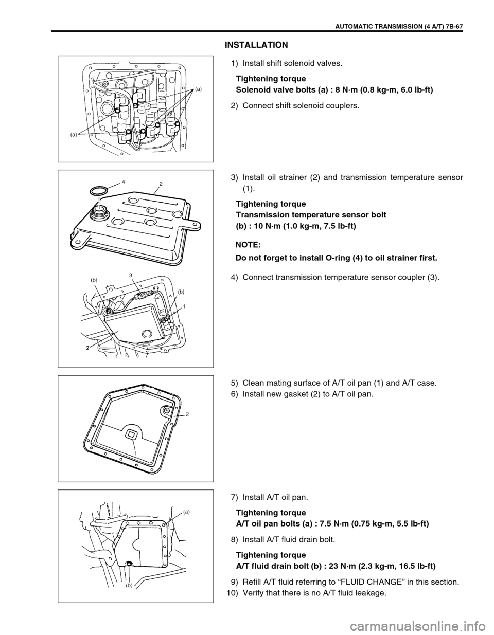
1) Install shift solenoid valves.
Tightening torque
Solenoid valve bolts (a) : 8 N·m (0.8 kg-m, 6.0 lb-ft)
2) Connect shift solenoid couplers.
3) Install oil strainer (2) and transmission temperature sensor
(1).
Tightening torque
Transmission temperature sensor bolt
(b) : 10 N·m (1.0 kg-m, 7.5 lb-ft)
4) Connect transmission temperature sensor coupler (3).
5) Clean mating surface of A/T oil pan (1) and A/T case.
6) Install new gasket (2) to A/T oil pan.
7) Install A/T oil pan.
Tightening torque
A/T oil pan bolts (a) : 7.5 N·m (0.75 kg-m, 5.5 lb-ft)
8) Install A/T fluid drain bolt.
Tightening torque
A/T fluid drain bolt (b) : 23 N·m (2.3 kg-m, 16.5 lb-ft)
9) Refill A/T fluid referring to “FLUID CHANGE” in this section.
10) Verify that there is no A/T fluid leakage.
NOTE:
Do not forget to install O-ring (4) to oil strainer first.
Page 110 of 447

7B-68 AUTOMATIC TRANSMISSION (4 A/T)
DIFFERENTIAL SIDE OIL SEAL
REPLACEMENT
1) Lift up vehicle and drain transmission oil.
2) Remove drive shaft joints from differential gear of transmis-
sion.
Refer to Section 4 for procedure to disconnect drive shaft
joints.
For differential side oil seal removal, it is not necessary to
remove drive shafts from steering knuckle.
For 4WD vehicle, remove transfer referring to Section 7D.
3) Remove differential side oil seal (1) by using flat end rod or
like.
4) Install new differential side oil seal by using special tool.
Special tool
(A) : 09940-53111
(B) : 09913-75510
5) Install drive shaft referring to Section 4.
6) Refill A/T fluid referring to “FLUID CHANGE” in this section. NOTE:
For oil seal installation, press-fit oil seal so that transmis-
sion case end face is flush with oil seal end face.
2. Steering gear box
3. A/T oil pan
4. Torque converter hous-
ing
5. Transmission case