TOYOTA CAMRY V20 1986 Service Information
CAMRY V20 1986
TOYOTA
TOYOTA
https://www.carmanualsonline.info/img/14/57449/w960_57449-0.png
TOYOTA CAMRY V20 1986 Service Information
Trending: brake light, ignition, hood open, emergency towing, ac relay, change time, oil temperature
Page 2021 of 2389
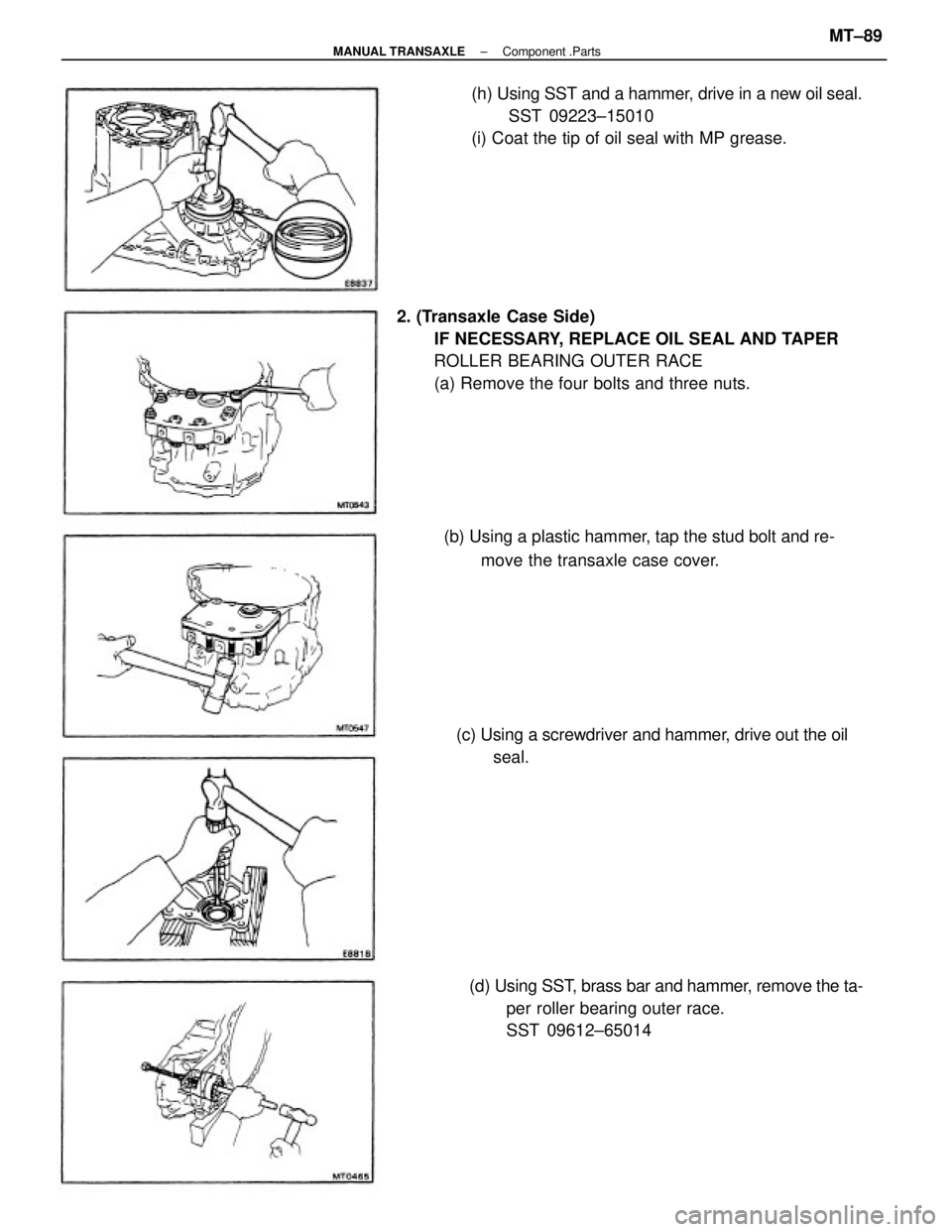
2. (Transaxle Case Side)
IF NECESSARY, REPLACE OIL SEAL AND TAPER
ROLLER BEARING OUTER RACE
(a) Remove the four bolts and three nuts.(h) Using SST and a hammer, drive in a new oil seal.
SST 09223±15010
(i) Coat the tip of oil seal with MP grease.
(c) Using a screwdriver and hammer, drive out the oil
seal.
(d) Using SST, brass bar and hammer, remove the ta-
per roller bearing outer race.
SST 09612±65014 (b) Using a plastic hammer, tap the stud bolt and re-
move the transaxle case cover.
± MANUAL TRANSAXLEComponent .PartsMT±89
Page 2022 of 2389
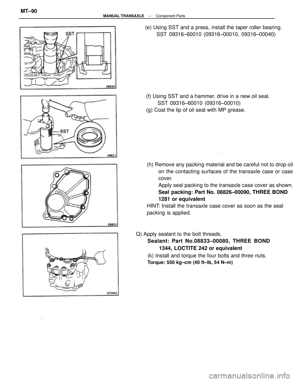
(h) Remove any packing material and be careful not to drop oil
on the contacting surfaces of the transaxle case or case
cover.
Apply seal packing to the transaxle case cover as shown.
Seal packing: Part No. 08826±00090, THREE BOND
1281 or equivalent
HINT: Install the transaxle case cover as soon as the seal
packing is applied.
Q) Apply sealant to the bolt threads.
Sealant: Part No.08833±00080, THREE BOND
1344, LOCTITE 242 or equivalent
(k) Install and torque the four bolts and three nuts.
Torque: 550 kg±cm (40 ft±lb, 54 N±m)
(f) Using SST and a hammer, drive in a new oil seal.
SST 09316±60010 (09316±00010)
(g) Coat the lip of oil seal with MP grease. (e) Using SST and a press, install the taper roller bearing.
SST 09316±60010 (09316±00010, 09316±00040)
± MANUAL TRANSAXLEComponent PartsMT±90
Page 2023 of 2389
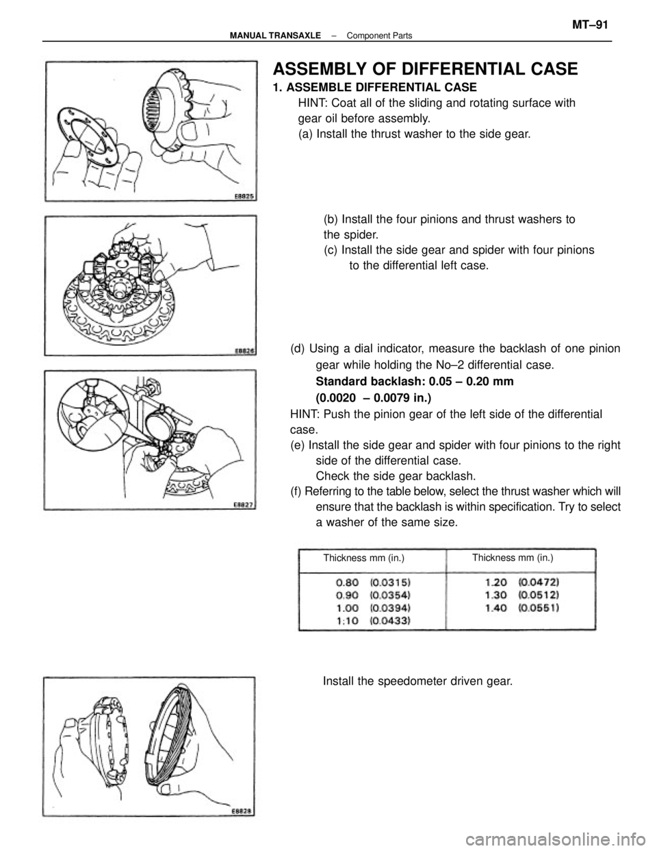
(d) Using a dial indicator, measure the backlash of one pinion
gear while holding the No±2 differential case.
Standard backlash: 0.05 ± 0.20 mm
(0.0020 ± 0.0079 in.)
HINT: Push the pinion gear of the left side of the differential
case.
(e) Install the side gear and spider with four pinions to the right
side of the differential case.
Check the side gear backlash.
(f) Referring to the table below, select the thrust washer which will
ensure that the backlash is within specification. Try to select
a washer of the same size.
ASSEMBLY OF DIFFERENTIAL CASE
1. ASSEMBLE DIFFERENTIAL CASE
HINT: Coat all of the sliding and rotating surface with
gear oil before assembly.
(a) Install the thrust washer to the side gear.
(b) Install the four pinions and thrust washers to
the spider.
(c) Install the side gear and spider with four pinions
to the differential left case.
Install the speedometer driven gear.
Thickness mm (in.)Thickness mm (in.)
± MANUAL TRANSAXLEComponent PartsMT±91
Page 2024 of 2389
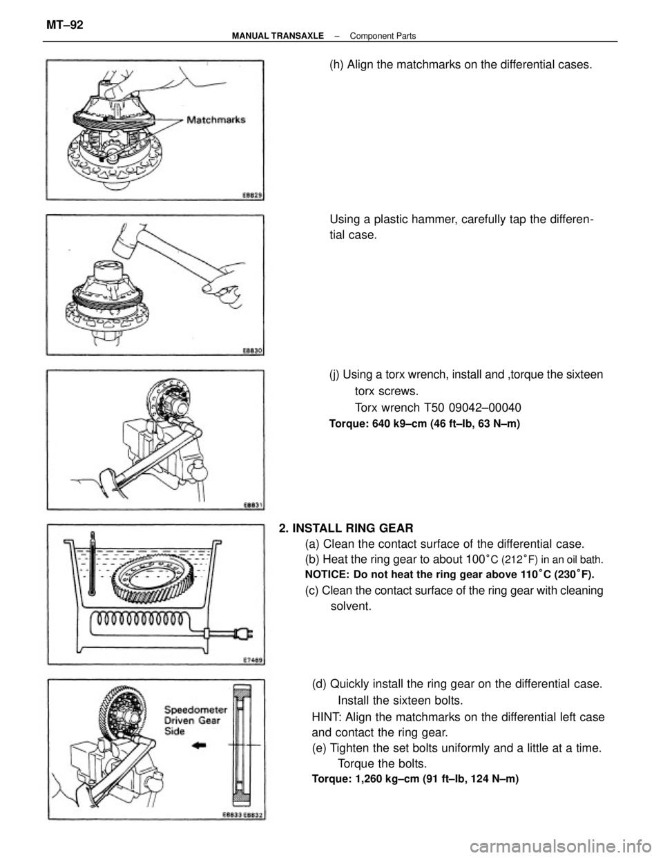
2. INSTALL RING GEAR
(a) Clean the contact surface of the differential case.
(b) Heat the ring gear to about 100
°C (212°F) in an oil bath.
NOTICE: Do not heat the ring gear above 110°C (230°F).
(c) Clean the contact surface of the ring gear with cleaning
solvent.
(d) Quickly install the ring gear on the differential case.
Install the sixteen bolts.
HINT: Align the matchmarks on the differential left case
and contact the ring gear.
(e) Tighten the set bolts uniformly and a little at a time.
Torque the bolts.
Torque: 1,260 kg±cm (91 ft±Ib, 124 N±m)
(j) Using a torx wrench, install and ,torque the sixteen
torx screws.
Torx wrench T50 09042±00040
Torque: 640 k9±cm (46 ft±Ib, 63 N±m)
Using a plastic hammer, carefully tap the differen-
tial case. (h) Align the matchmarks on the differential cases.
± MANUAL TRANSAXLEComponent PartsMT±92
Page 2025 of 2389
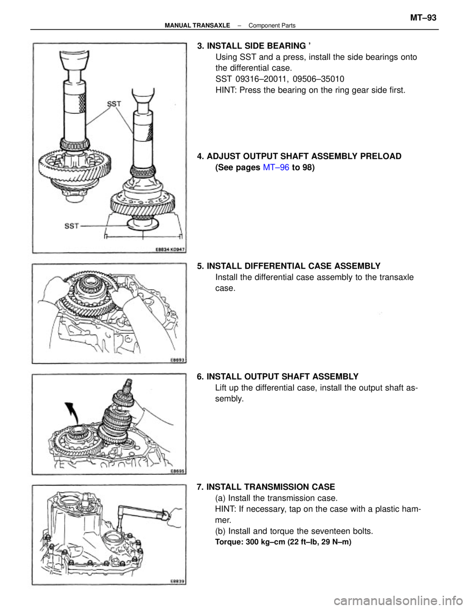
7. INSTALL TRANSMISSION CASE
(a) Install the transmission case.
HINT: If necessary, tap on the case with a plastic ham-
mer.
(b) Install and torque the seventeen bolts.
Torque: 300 kg±cm (22 ft±lb, 29 N±m)
3. INSTALL SIDE BEARING '
Using SST and a press, install the side bearings onto
the differential case.
SST 09316±20011, 09506±35010
HINT: Press the bearing on the ring gear side first.
5. INSTALL DIFFERENTIAL CASE ASSEMBLY
Install the differential case assembly to the transaxle
case.
6. INSTALL OUTPUT SHAFT ASSEMBLY
Lift up the differential case, install the output shaft as-
sembly. 4. ADJUST OUTPUT SHAFT ASSEMBLY PRELOAD
(See pages MT±96 to 98)
± MANUAL TRANSAXLEComponent PartsMT±93
Page 2026 of 2389
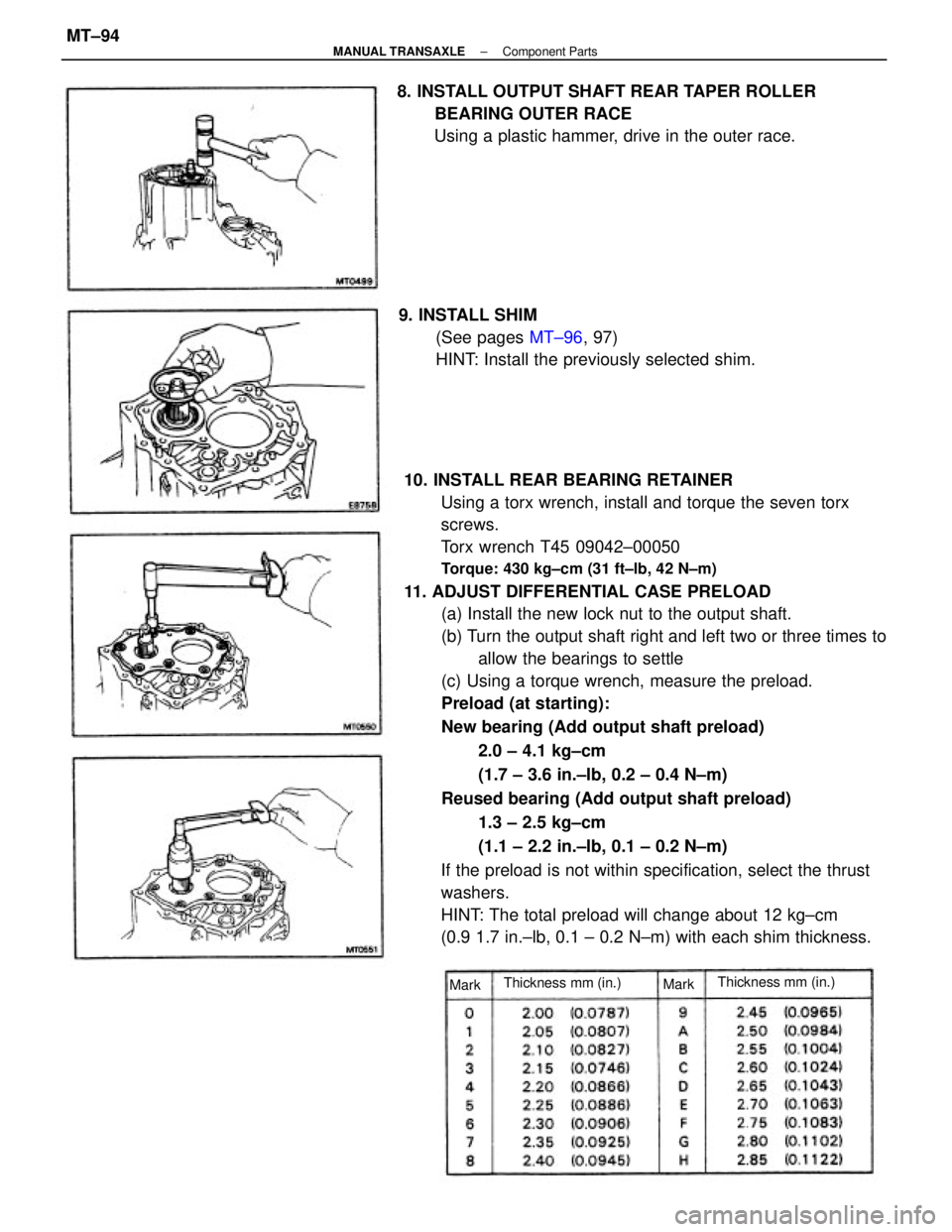
10. INSTALL REAR BEARING RETAINER
Using a torx wrench, install and torque the seven torx
screws.
Torx wrench T45 09042±00050
Torque: 430 kg±cm (31 ft±lb, 42 N±m)
11. ADJUST DIFFERENTIAL CASE PRELOAD
(a) Install the new lock nut to the output shaft.
(b) Turn the output shaft right and left two or three times to
allow the bearings to settle
(c) Using a torque wrench, measure the preload.
Preload (at starting):
New bearing (Add output shaft preload)
2.0 ± 4.1 kg±cm
(1.7 ± 3.6 in.±Ib, 0.2 ± 0.4 N±m)
Reused bearing (Add output shaft preload)
1.3 ± 2.5 kg±cm
(1.1 ± 2.2 in.±Ib, 0.1 ± 0.2 N±m)
If the preload is not within specification, select the thrust
washers.
HINT: The total preload will change about 12 kg±cm
(0.9 1.7 in.±lb, 0.1 ± 0.2 N±m) with each shim thickness. 8. INSTALL OUTPUT SHAFT REAR TAPER ROLLER
BEARING OUTER RACE
Using a plastic hammer, drive in the outer race.
9. INSTALL SHIM
(See pages MT±96, 97)
HINT: Install the previously selected shim.
Thickness mm (in.)Thickness mm (in.)
MarkMark
± MANUAL TRANSAXLEComponent PartsMT±94
Page 2027 of 2389
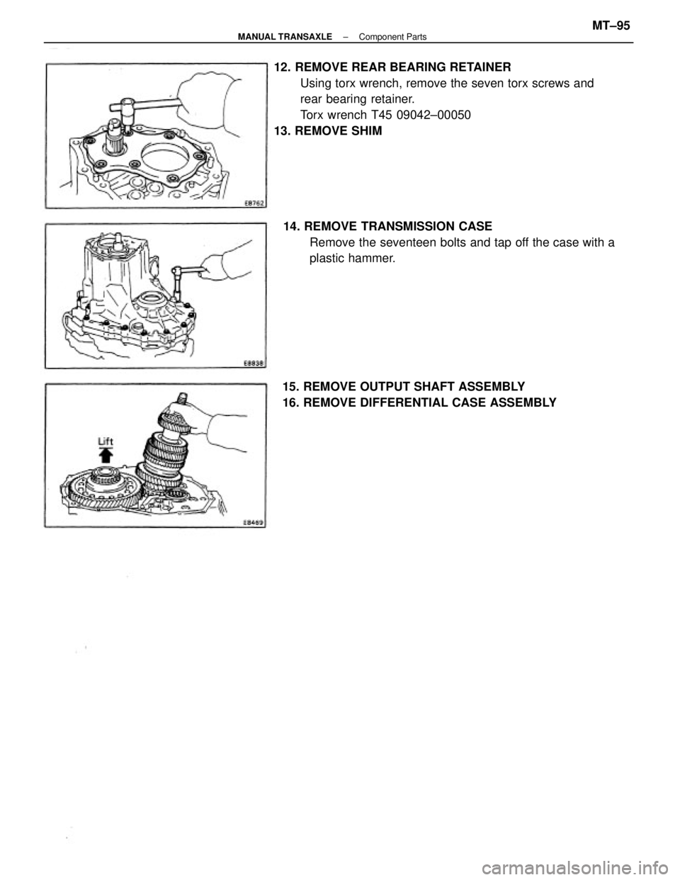
12. REMOVE REAR BEARING RETAINER
Using torx wrench, remove the seven torx screws and
rear bearing retainer.
Torx wrench T45 09042±00050
13. REMOVE SHIM
14. REMOVE TRANSMISSION CASE
Remove the seventeen bolts and tap off the case with a
plastic hammer.
15. REMOVE OUTPUT SHAFT ASSEMBLY
16. REMOVE DIFFERENTIAL CASE ASSEMBLY
± MANUAL TRANSAXLEComponent PartsMT±95
Page 2028 of 2389
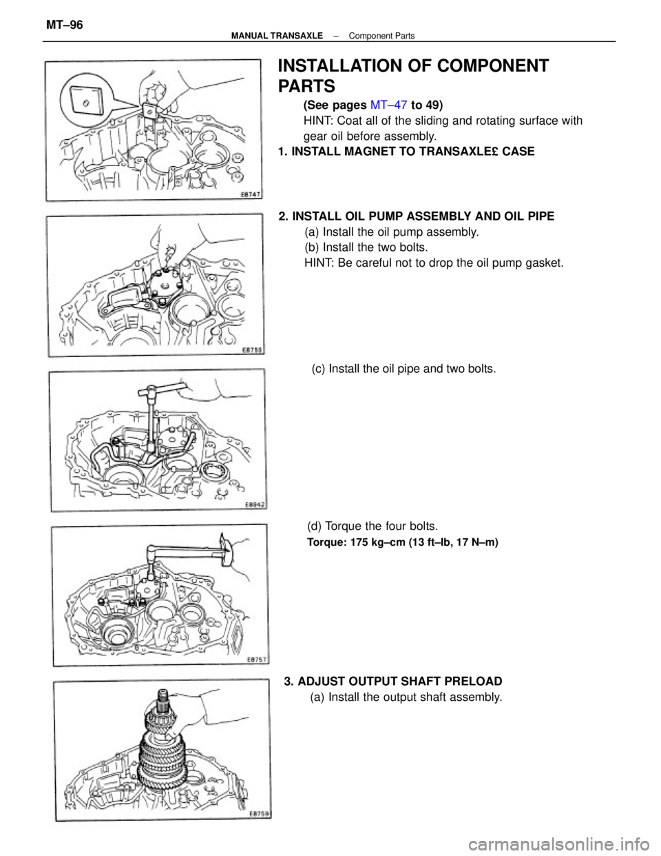
INSTALLATION OF COMPONENT
PARTS
(See pages MT±47 to 49)
HINT: Coat all of the sliding and rotating surface with
gear oil before assembly.
1. INSTALL MAGNET TO TRANSAXLE£ CASE
2. INSTALL OIL PUMP ASSEMBLY AND OIL PIPE
(a) Install the oil pump assembly.
(b) Install the two bolts.
HINT: Be careful not to drop the oil pump gasket.
3. ADJUST OUTPUT SHAFT PRELOAD
(a) Install the output shaft assembly. (d) Torque the four bolts.
Torque: 175 kg±cm (13 ft±Ib, 17 N±m)
(c) Install the oil pipe and two bolts.
± MANUAL TRANSAXLEComponent PartsMT±96
Page 2029 of 2389
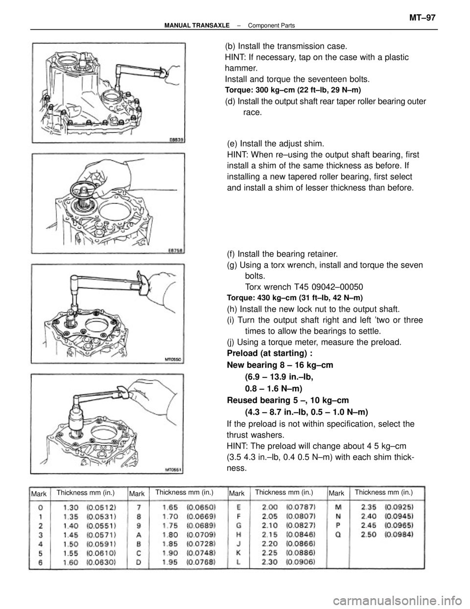
(f) Install the bearing retainer.
(g) Using a torx wrench, install and torque the seven
bolts.
Torx wrench T45 09042±00050
Torque: 430 kg±cm (31 ft±Ib, 42 N±m)
(h) Install the new lock nut to the output shaft.
(i) Turn the output shaft right and left 'two or three
times to allow the bearings to settle.
(j) Using a torque meter, measure the preload.
Preload (at starting) :
New bearing 8 ± 16 kg±cm
(6.9 ± 13.9 in.±Ib,
0.8 ± 1.6 N±m)
Reused bearing 5 ±, 10 kg±cm
(4.3 ± 8.7 in.±lb, 0.5 ± 1.0 N±m)
If the preload is not within specification, select the
thrust washers.
HINT: The preload will change about 4 5 kg±cm
(3.5 4.3 in.±lb, 0.4 0.5 N±m) with each shim thick-
ness. (b) Install the transmission case.
HINT: If necessary, tap on the case with a plastic
hammer.
Install and torque the seventeen bolts.
Torque: 300 kg±cm (22 ft±lb, 29 N±m)
(d) Install the output shaft rear taper roller bearing outer
race.
(e) Install the adjust shim.
HINT: When re±using the output shaft bearing, first
install a shim of the same thickness as before. If
installing a new tapered roller bearing, first select
and install a shim of lesser thickness than before.
Thickness mm (in.) Thickness mm (in.)
Thickness mm (in.)Thickness mm (in.)
Mark
MarkMarkMark
± MANUAL TRANSAXLEComponent PartsMT±97
Page 2030 of 2389
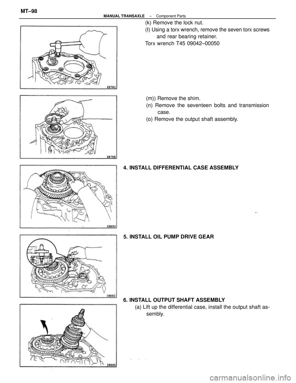
(k) Remove the lock nut.
(I) Using a torx wrench, remove the seven torx screws
and rear bearing retainer.
Torx wrench T45 09042±00050
6. INSTALL OUTPUT SHAFT ASSEMBLY
(a) Lift up the differential case, install the output shaft as-
sembly. (m)) Remove the shim.
(n) Remove the seventeen bolts and transmission
case.
(o) Remove the output shaft assembly.
4. INSTALL DIFFERENTIAL CASE ASSEMBLY
5. INSTALL OIL PUMP DRIVE GEAR
± MANUAL TRANSAXLEComponent PartsMT±98
Trending: towing, ad blue, mileage, display, headlight bulb, belt, automatic transmission
