TOYOTA CAMRY V20 1986 Service Information
CAMRY V20 1986
TOYOTA
TOYOTA
https://www.carmanualsonline.info/img/14/57449/w960_57449-0.png
TOYOTA CAMRY V20 1986 Service Information
Trending: automatic transmission, headlight bulb, transmission oil, gas type, compression ratio, buttons, gas mileage
Page 2011 of 2389
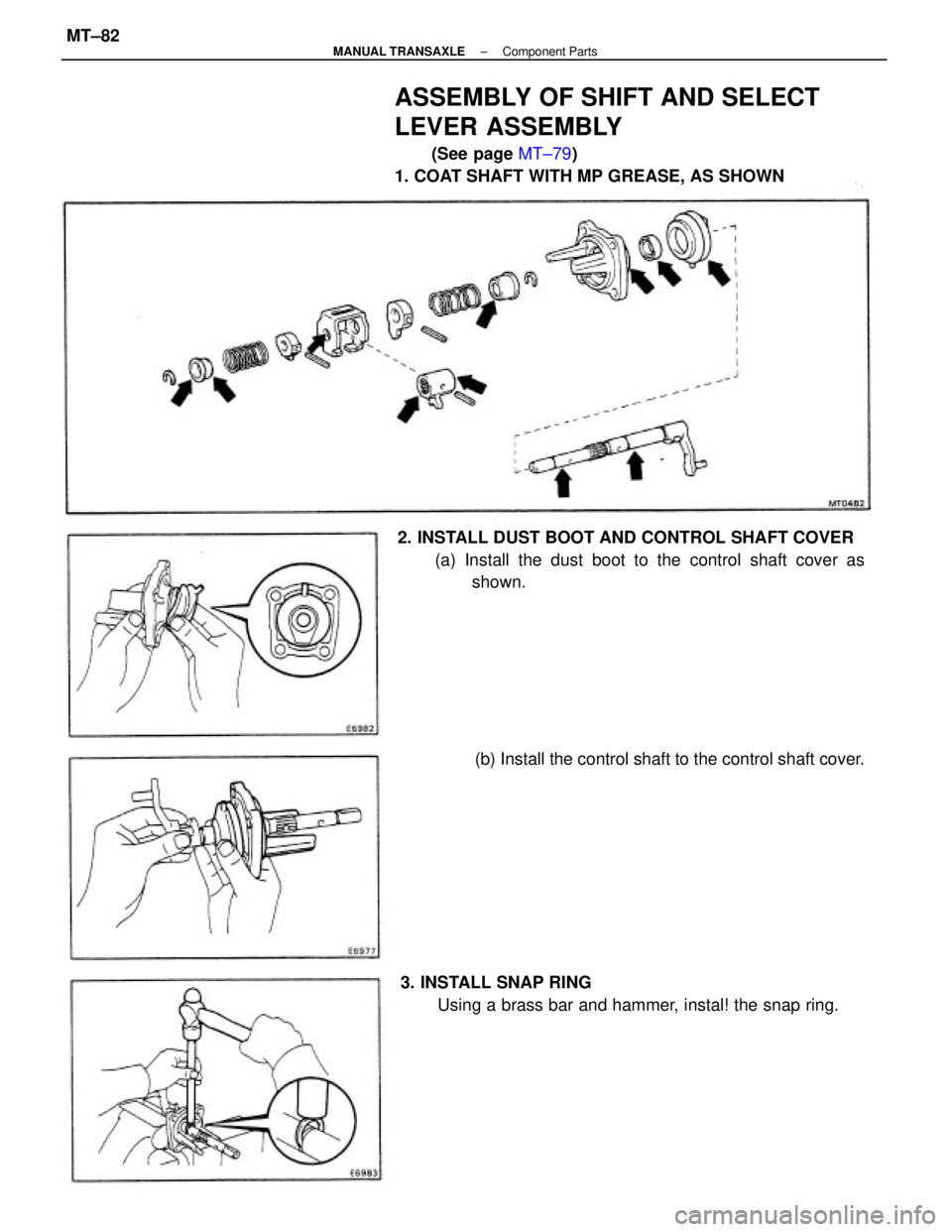
ASSEMBLY OF SHIFT AND SELECT
LEVER ASSEMBLY
(See page MT±79)
1. COAT SHAFT WITH MP GREASE, AS SHOWN
2. INSTALL DUST BOOT AND CONTROL SHAFT COVER
(a) Install the dust boot to the control shaft cover as
shown.
3. INSTALL SNAP RING
Using a brass bar and hammer, instal! the snap ring.(b) Install the control shaft to the control shaft cover.
± MANUAL TRANSAXLEComponent PartsMT±82
Page 2012 of 2389
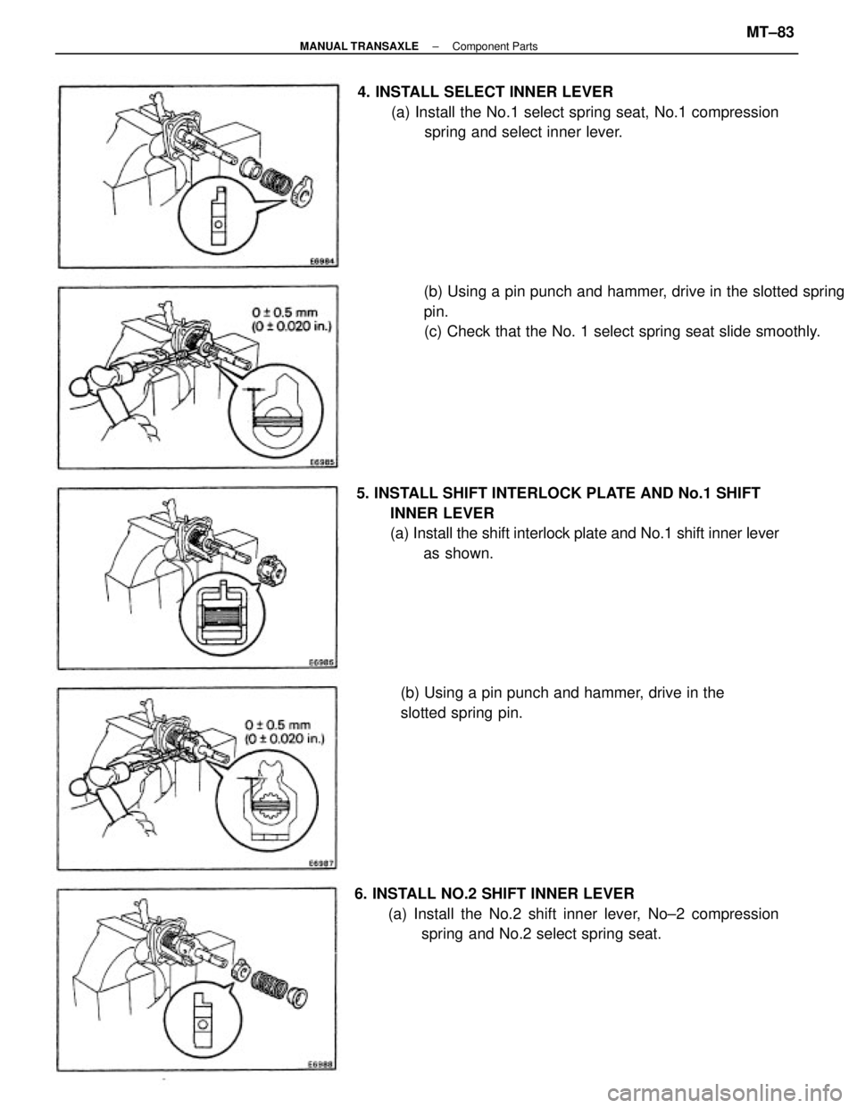
5. INSTALL SHIFT INTERLOCK PLATE AND No.1 SHIFT
INNER LEVER
(a) Install the shift interlock plate and No.1 shift inner lever
as shown.(b) Using a pin punch and hammer, drive in the slotted spring
pin.
(c) Check that the No. 1 select spring seat slide smoothly. 4. INSTALL SELECT INNER LEVER
(a) Install the No.1 select spring seat, No.1 compression
spring and select inner lever.
6. INSTALL NO.2 SHIFT INNER LEVER
(a) Install the No.2 shift inner lever, No±2 compression
spring and No.2 select spring seat. (b) Using a pin punch and hammer, drive in the
slotted spring pin.
± MANUAL TRANSAXLEComponent PartsMT±83
Page 2013 of 2389
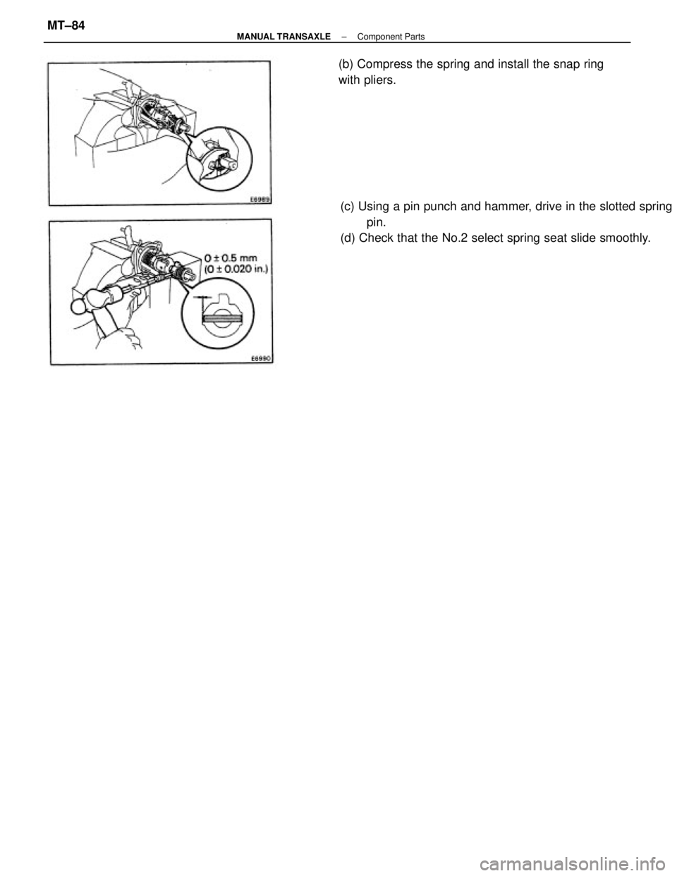
(c) Using a pin punch and hammer, drive in the slotted spring
pin.
(d) Check that the No.2 select spring seat slide smoothly. (b) Compress the spring and install the snap ring
with pliers.
± MANUAL TRANSAXLEComponent PartsMT±84
Page 2014 of 2389
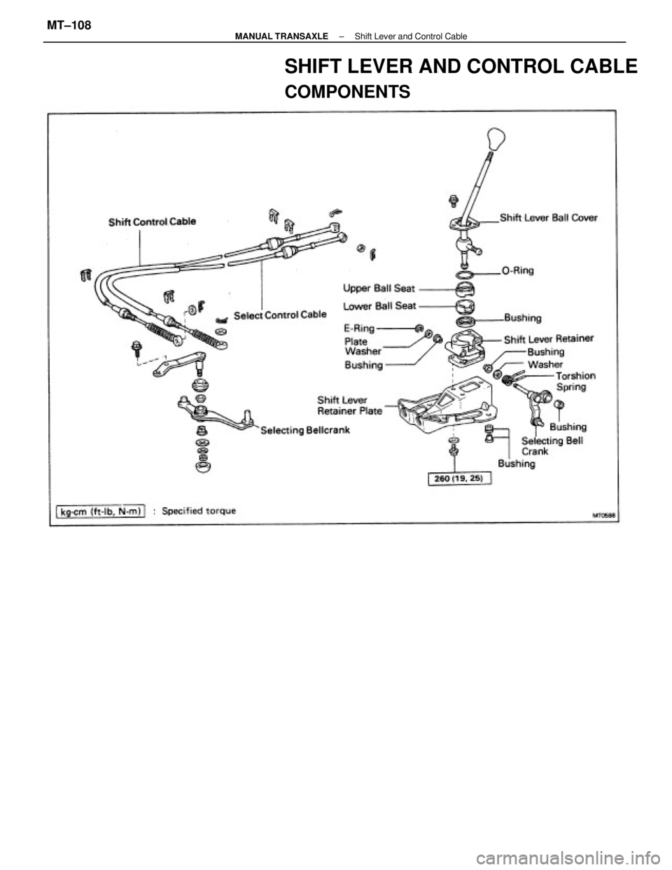
SHIFT LEVER AND CONTROL CABLE
COMPONENTS
± MANUAL TRANSAXLEShift Lever and Control CableMT±108
Page 2015 of 2389
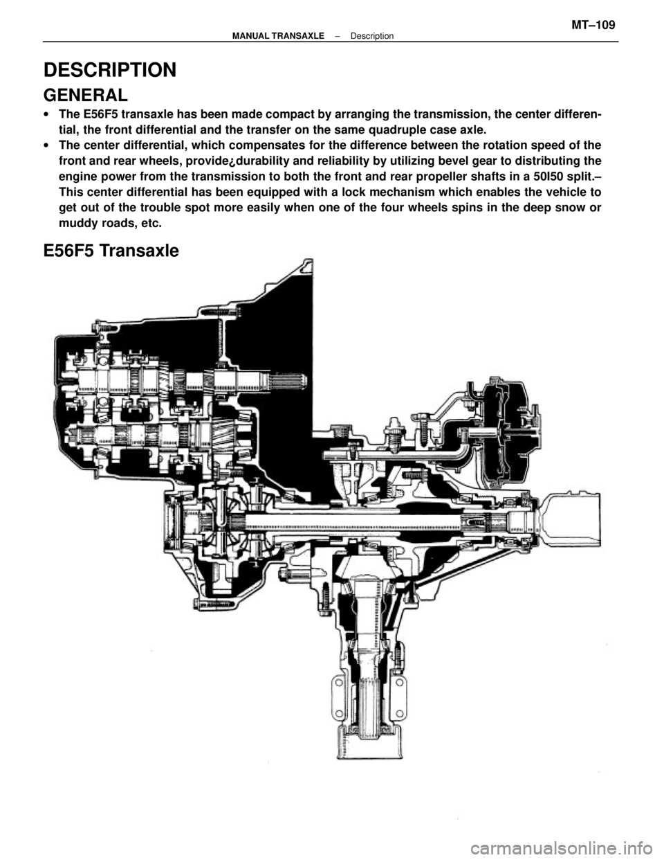
DESCRIPTION
GENERAL
wThe E56F5 transaxle has been made compact by arranging the transmission, the center differen-
tial, the front differential and the transfer on the same quadruple case axle.
wThe center differential, which compensates for the difference between the rotation speed of the
front and rear wheels, provide¿durability and reliability by utilizing bevel gear to distributing the
engine power from the transmission to both the front and rear propeller shafts in a 50I50 split.±
This center differential has been equipped with a lock mechanism which enables the vehicle to
get out of the trouble spot more easily when one of the four wheels spins in the deep snow or
muddy roads, etc.
E56F5 Transaxle
± MANUAL TRANSAXLEDescriptionMT±109
Page 2016 of 2389
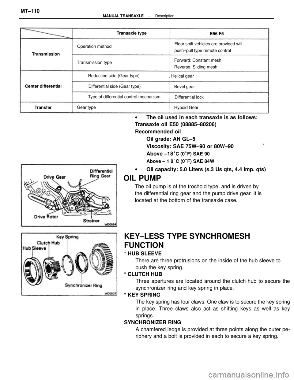
KEY±LESS TYPE SYNCHROMESH
FUNCTION
* HUB SLEEVE
There are three protrusions on the inside of the hub sleeve to
push the key spring.
* CLUTCH HUB
Three apertures are located around the clutch hub to secure the
synchronizer ring and key spring in place.
* KEY SPRING
The key spring has four claws. One claw is to secure the key spring
in place. Three claws also act as shifting keys as well as key
springs.
SYNCHRONIZER RING
A chamfered ledge is provided at three points along the outer pe-
riphery and a bolt is provided in each to secure a key spring. wThe oil used in each transaxle is as follows:
Transaxle oil E50 (08885±80206)
Recommended oil
Oil grade: AN GL±5
Viscosity: SAE 75W±90 or 80W±90
Above ±18
°C (0°F) SAE 90
Above ± 1 8°C (0°F) SAE 84W
wOil capacity: 5.0 Liters (s.3 Us qts, 4.4 Imp. qts)
OIL PUMP
The oil pump is of the trochoid type, and is driven by
the differential ring gear and the pump drive gear. It is
located at the bottom of the transaxle case.
Floor shift vehicles are provided will
push±pull type remote control
Forward: Constant mesh
Reverse: Sliding mesh
Type of differential control mechanismDifferential side (Gear type) Reduction side (Gear type) Transmission typeOperation method
Center differential. Helical gear
Differential lock Transaxle type
Hypoid Gear Transmission
Bevel gear
Gear type
TransferE56 F5
± MANUAL TRANSAXLEDescriptionMT±110
Page 2017 of 2389
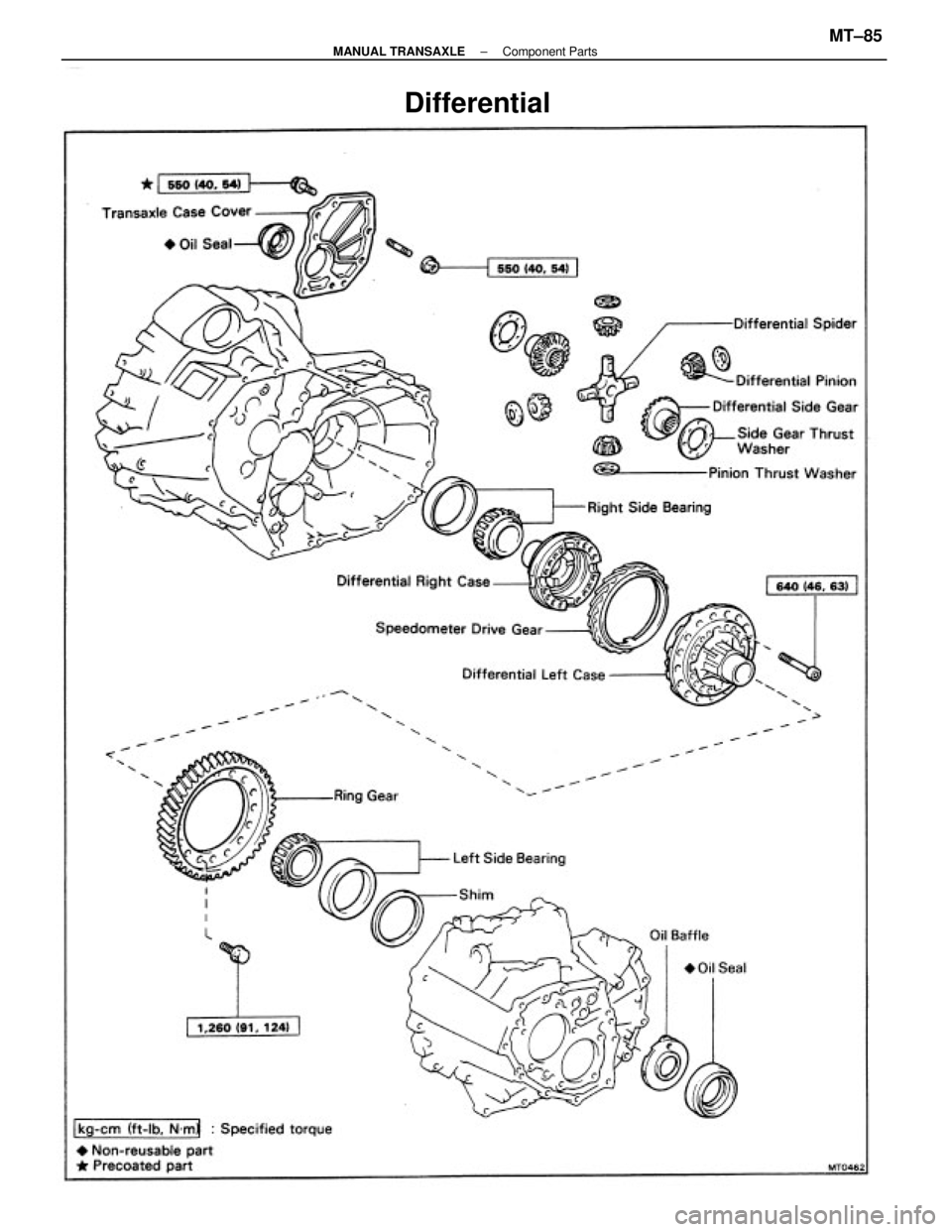
Differential
± MANUAL TRANSAXLEComponent PartsMT±85
Page 2018 of 2389
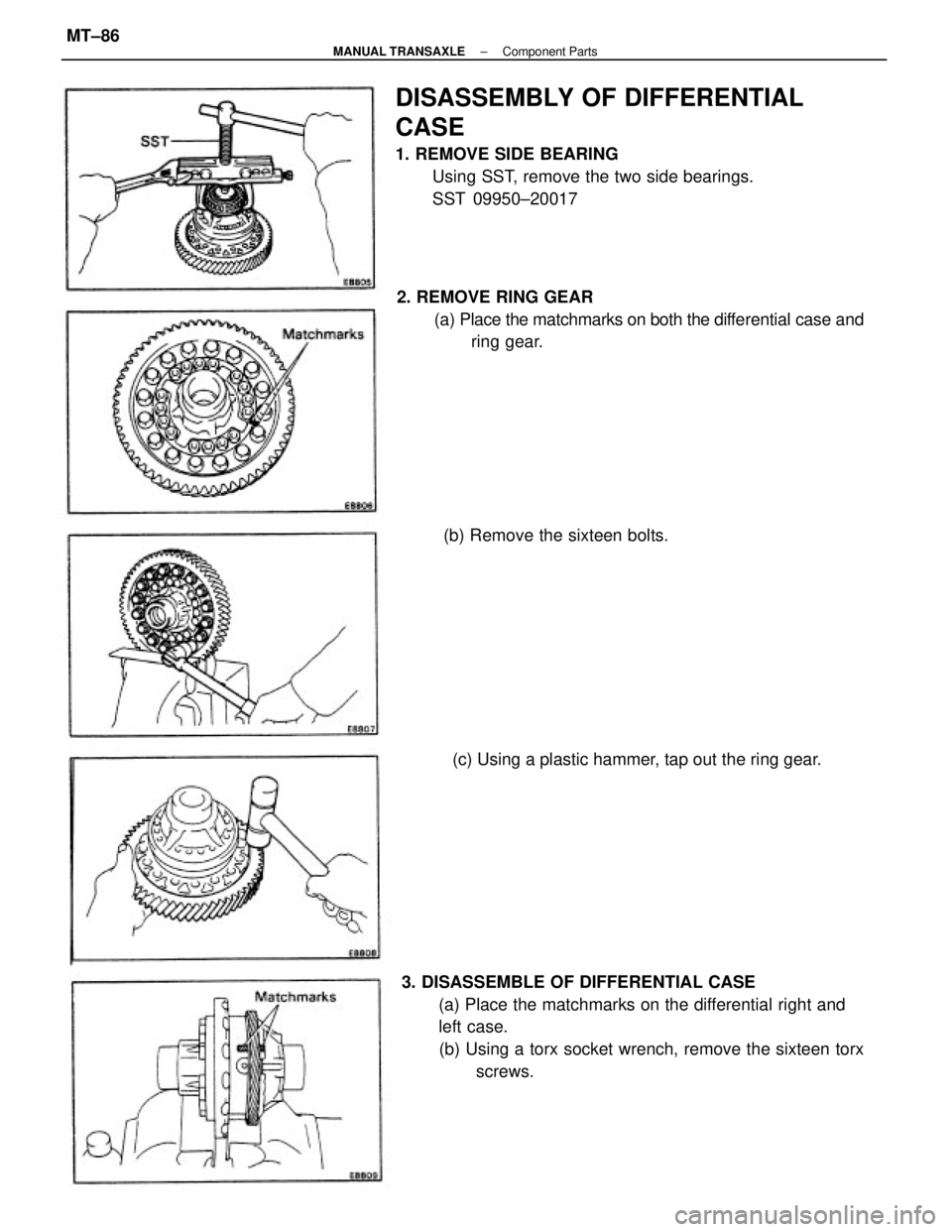
3. DISASSEMBLE OF DIFFERENTIAL CASE
(a) Place the matchmarks on the differential right and
left case.
(b) Using a torx socket wrench, remove the sixteen torx
screws. 2. REMOVE RING GEAR
(a) Place the matchmarks on both the differential case and
ring gear.
DISASSEMBLY OF DIFFERENTIAL
CASE
1. REMOVE SIDE BEARING
Using SST, remove the two side bearings.
SST 09950±20017
(c) Using a plastic hammer, tap out the ring gear. (b) Remove the sixteen bolts.
± MANUAL TRANSAXLEComponent PartsMT±86
Page 2019 of 2389
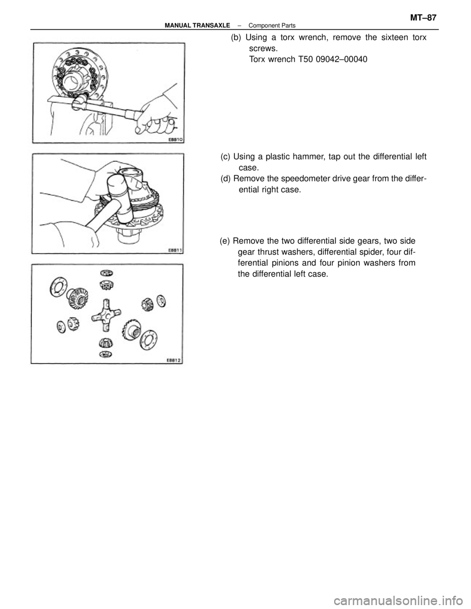
(e) Remove the two differential side gears, two side
gear thrust washers, differential spider, four dif-
ferential pinions and four pinion washers from
the differential left case. (c) Using a plastic hammer, tap out the differential left
case.
(d) Remove the speedometer drive gear from the differ-
ential right case. (b) Using a torx wrench, remove the sixteen torx
screws.
Torx wrench T50 09042±00040
± MANUAL TRANSAXLEComponent PartsMT±87
Page 2020 of 2389
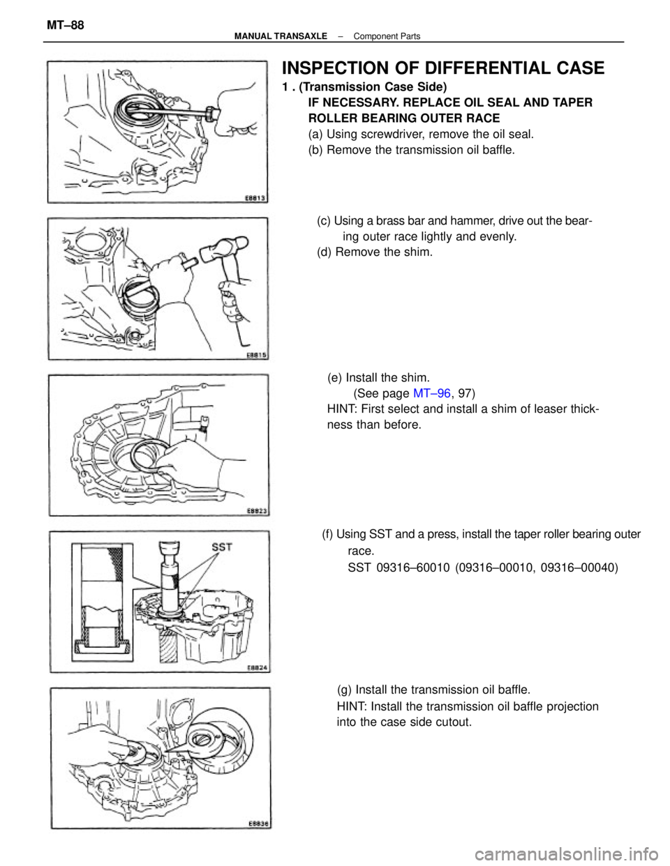
INSPECTION OF DIFFERENTIAL CASE
1 . (Transmission Case Side)
IF NECESSARY. REPLACE OIL SEAL AND TAPER
ROLLER BEARING OUTER RACE
(a) Using screwdriver, remove the oil seal.
(b) Remove the transmission oil baffle.
(e) Install the shim.
(See page MT±96, 97)
HINT: First select and install a shim of leaser thick-
ness than before.
(g) Install the transmission oil baffle.
HINT: Install the transmission oil baffle projection
into the case side cutout. (f) Using SST and a press, install the taper roller bearing outer
race.
SST 09316±60010 (09316±00010, 09316±00040) (c) Using a brass bar and hammer, drive out the bear-
ing outer race lightly and evenly.
(d) Remove the shim.
± MANUAL TRANSAXLEComponent PartsMT±88
Trending: spark plugs, rear view mirror, ABS, hood open, heating, service reset, rims
