TOYOTA CAMRY V20 1986 Service Information
Manufacturer: TOYOTA, Model Year: 1986, Model line: CAMRY V20, Model: TOYOTA CAMRY V20 1986Pages: 2389, PDF Size: 84.44 MB
Page 301 of 2389
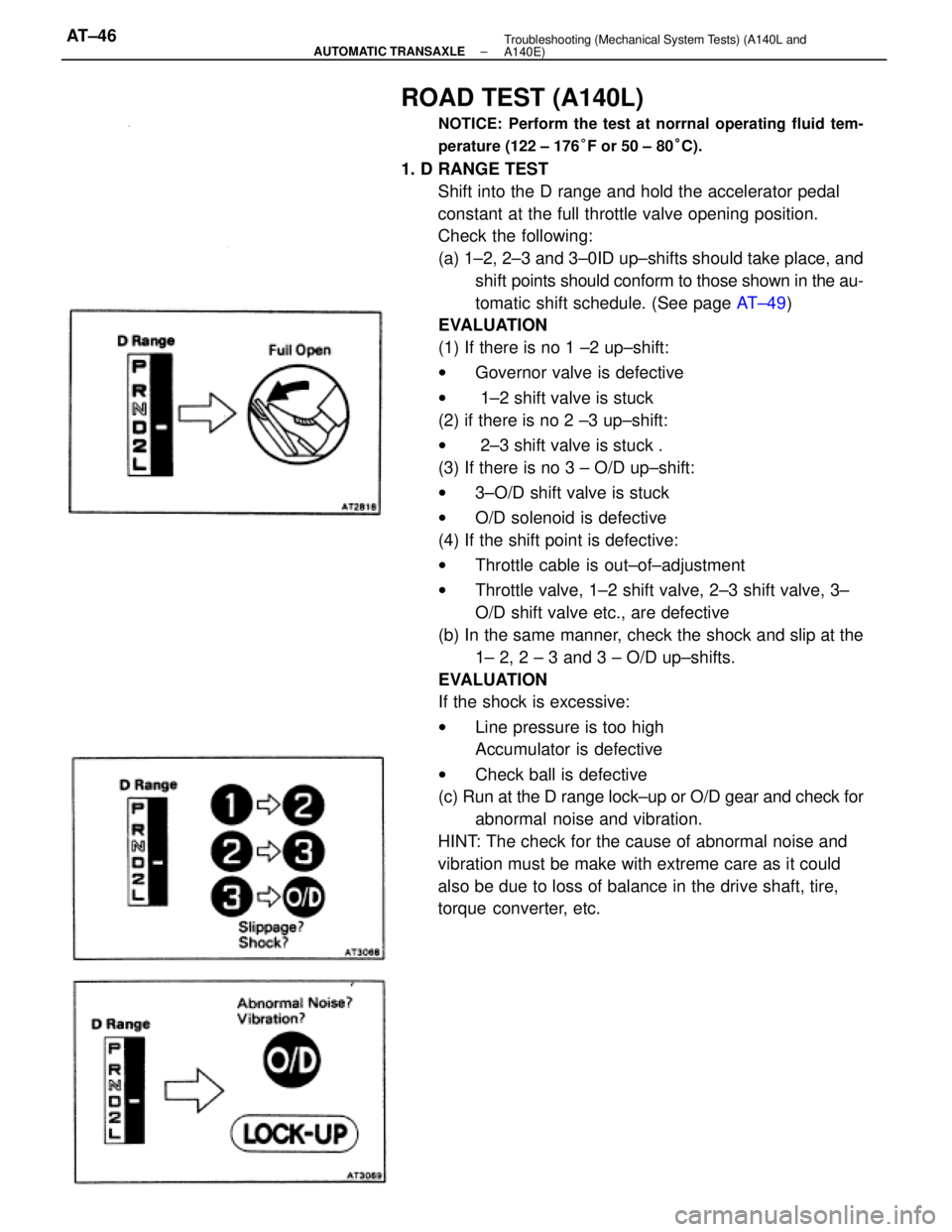
ROAD TEST (A140L)
NOTICE: Perform the test at norrnal operating fluid tem-
perature (122 ± 176°F or 50 ± 80°C).
1. D RANGE TEST
Shift into the D range and hold the accelerator pedal
constant at the full throttle valve opening position.
Check the following:
(a) 1±2, 2±3 and 3±0ID up±shifts should take place, and
shift points should conform to those shown in the au-
tomatic shift schedule. (See page AT±49)
EVALUATION
(1) If there is no 1 ±2 up±shift:
wGovernor valve is defective
w 1±2 shift valve is stuck
(2) if there is no 2 ±3 up±shift:
w 2±3 shift valve is stuck .
(3) If there is no 3 ± O/D up±shift:
w3±O/D shift valve is stuck
wO/D solenoid is defective
(4) If the shift point is defective:
wThrottle cable is out±of±adjustment
wThrottle valve, 1±2 shift valve, 2±3 shift valve, 3±
O/D shift valve etc., are defective
(b) In the same manner, check the shock and slip at the
1± 2, 2 ± 3 and 3 ± O/D up±shifts.
EVALUATION
If the shock is excessive:
wLine pressure is too high
Accumulator is defective
wCheck ball is defective
(c) Run at the D range lock±up or O/D gear and check for
abnormal noise and vibration.
HINT: The check for the cause of abnormal noise and
vibration must be make with extreme care as it could
also be due to loss of balance in the drive shaft, tire,
torque converter, etc.
± AUTOMATIC TRANSAXLETroubleshooting (Mechanical System Tests) (A140L and
A140E)AT±46
Page 302 of 2389
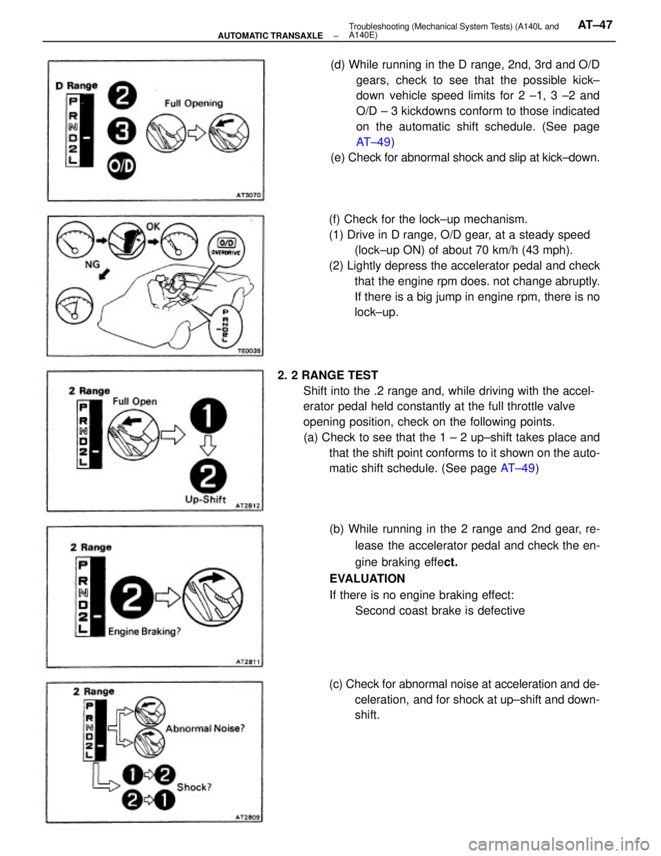
2. 2 RANGE TEST
Shift into the .2 range and, while driving with the accel-
erator pedal held constantly at the full throttle valve
opening position, check on the following points.
(a) Check to see that the 1 ± 2 up±shift takes place and
that the shift point conforms to it shown on the auto-
matic shift schedule. (See page AT±49) (f) Check for the lock±up mechanism.
(1) Drive in D range, O/D gear, at a steady speed
(lock±up ON) of about 70 km/h (43 mph).
(2) Lightly depress the accelerator pedal and check
that the engine rpm does. not change abruptly.
If there is a big jump in engine rpm, there is no
lock±up.
(b) While running in the 2 range and 2nd gear, re-
lease the accelerator pedal and check the en-
gine braking effect.
EVALUATION
If there is no engine braking effect:
Second coast brake is defective (d) While running in the D range, 2nd, 3rd and O/D
gears, check to see that the possible kick±
down vehicle speed limits for 2 ±1, 3 ±2 and
O/D ± 3 kickdowns conform to those indicated
on the automatic shift schedule. (See page
AT±49)
(e) Check for abnormal shock and slip at kick±down.
(c) Check for abnormal noise at acceleration and de-
celeration, and for shock at up±shift and down-
shift.
± AUTOMATIC TRANSAXLETroubleshooting (Mechanical System Tests) (A140L and
A140E)AT±47
Page 303 of 2389
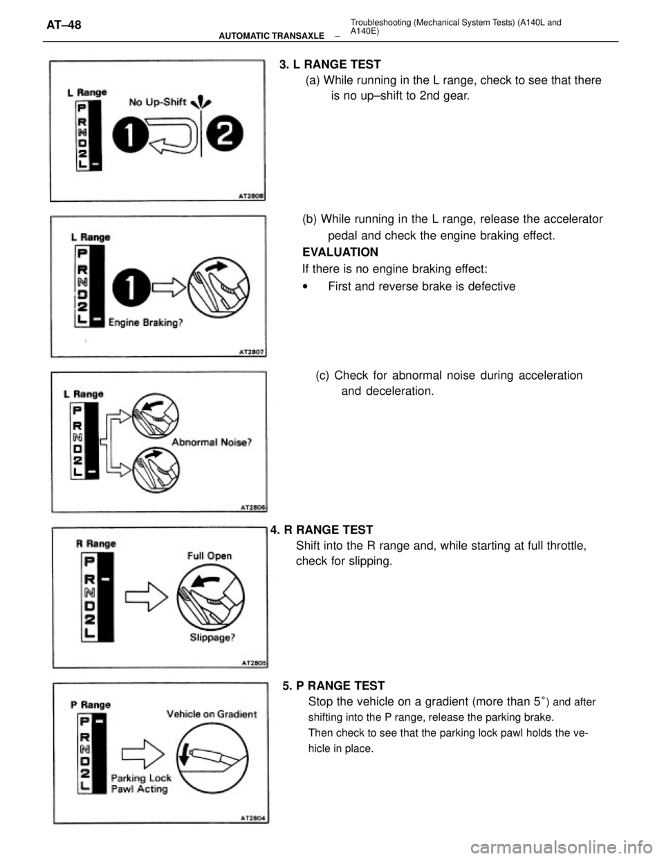
(b) While running in the L range, release the accelerator
pedal and check the engine braking effect.
EVALUATION
If there is no engine braking effect:
wFirst and reverse brake is defective
5. P RANGE TEST
Stop the vehicle on a gradient (more than 5
°) and after
shifting into the P range, release the parking brake.
Then check to see that the parking lock pawl holds the ve-
hicle in place.
4. R RANGE TEST
Shift into the R range and, while starting at full throttle,
check for slipping. 3. L RANGE TEST
(a) While running in the L range, check to see that there
is no up±shift to 2nd gear.
(c) Check for abnormal noise during acceleration
and deceleration.
± AUTOMATIC TRANSAXLETroubleshooting (Mechanical System Tests) (A140L and
A140E)AT±48
Page 304 of 2389
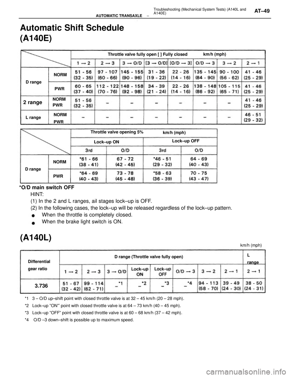
*O/D main switch OFF
HINT:
(1) In the 2 and L ranges, ail stages lock±up is OFF.
(2) In the following cases, the lock±up will be released regardless of the lock±up pattern.
When the throttle is completely closed.
When the brake light switch is ON.
*1 3 ± O/D up±shift point with closed throttle valve is at 32 ± 45 km/h (20 ± 28 mph).
*2 Lock±up ºONº' point with closed throttle valve is at 64 ± 73 km/h (40 ± 45 mph).
*3 Lock±up ºOFFº point with closed throttle valve is at 60 ± 68 km/h (37 ± 42 mph).
*4 O/D ±3 down±shift is possible up to maximum speed.
Automatic Shift Schedule
(A140E)
Throttle valve fully open [ ] Fully closed
D range (Throttle valve fully open) Throttle valve opening 5%
Differential
gear ratio
(A140L)
km/h (mph)
Lock±up OFF
km/h (mph) km/h (mph)
Lock±up ON NORM
PWR NORM
PWR
L
range D range
2 range
D range
L range
NORMNORM
3.736
PWRPWR
± AUTOMATIC TRANSAXLETroubleshooting (Mechanical System Tests) (A140L and
A140E)AT±49
Page 305 of 2389
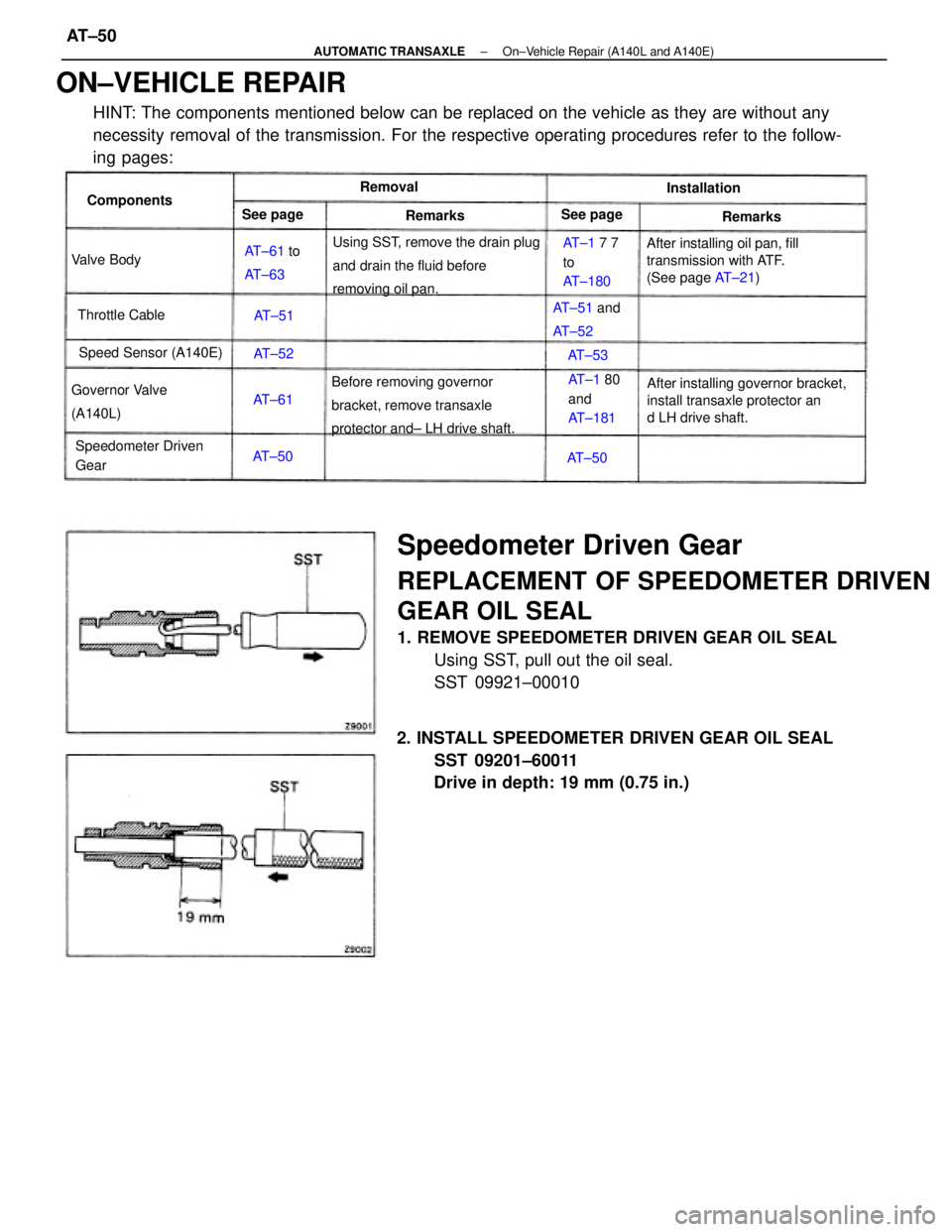
Speedometer Driven Gear
REPLACEMENT OF SPEEDOMETER DRIVEN
GEAR OIL SEAL
1. REMOVE SPEEDOMETER DRIVEN GEAR OIL SEAL
Using SST, pull out the oil seal.
SST 09921±00010
ON±VEHICLE REPAIR
HINT: The components mentioned below can be replaced on the vehicle as they are without any
necessity removal of the transmission. For the respective operating procedures refer to the follow-
ing pages:
2. INSTALL SPEEDOMETER DRIVEN GEAR OIL SEAL
SST 09201±60011
Drive in depth: 19 mm (0.75 in.)
After installing governor bracket,
install transaxle protector an
d LH drive shaft. Using SST, remove the drain plug
and drain the fluid before
removing oil pan.
Before removing governor
bracket, remove transaxle
protector and± LH drive shaft.After installing oil pan, fill
transmission with ATF.
(See page AT±21)
Speedometer Driven
Gear Governor Valve
(A140L)AT±1 7 7
to
AT±180
Speed Sensor (A140E)
AT±1 80
and
AT±181 AT±51 and
AT±52 AT±61 to
AT±63
Throttle CableComponents
Valve BodyInstallation
See page See pageRemoval
Remarks Remarks
AT±50 AT±61AT±51
AT±50AT±52
AT±53
± AUTOMATIC TRANSAXLEOn±Vehicle Repair (A140L and A140E)AT±50
Page 306 of 2389
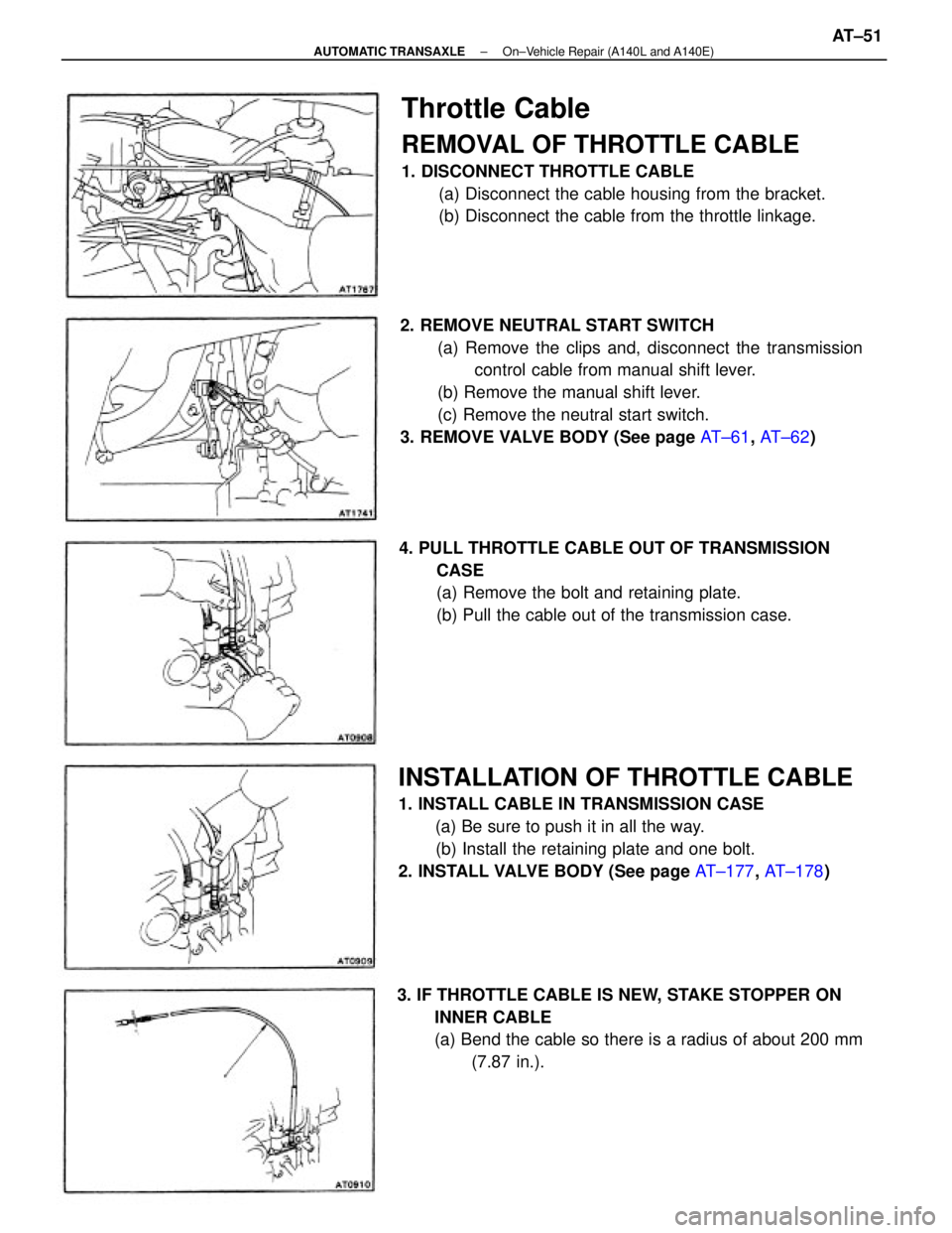
2. REMOVE NEUTRAL START SWITCH
(a) Remove the clips and, disconnect the transmission
control cable from manual shift lever.
(b) Remove the manual shift lever.
(c) Remove the neutral start switch.
3. REMOVE VALVE BODY (See page AT±61, AT±62)
INSTALLATION OF THROTTLE CABLE
1. INSTALL CABLE IN TRANSMISSION CASE
(a) Be sure to push it in all the way.
(b) Install the retaining plate and one bolt.
2. INSTALL VALVE BODY (See page AT±177, AT±178)
Throttle Cable
REMOVAL OF THROTTLE CABLE
1. DISCONNECT THROTTLE CABLE
(a) Disconnect the cable housing from the bracket.
(b) Disconnect the cable from the throttle linkage.
4. PULL THROTTLE CABLE OUT OF TRANSMISSION
CASE
(a) Remove the bolt and retaining plate.
(b) Pull the cable out of the transmission case.
3. IF THROTTLE CABLE IS NEW, STAKE STOPPER ON
INNER CABLE
(a) Bend the cable so there is a radius of about 200 mm
(7.87 in.).
± AUTOMATIC TRANSAXLEOn±Vehicle Repair (A140L and A140E)AT±51
Page 307 of 2389
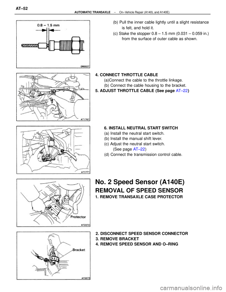
6. INSTALL NEUTRAL START SWITCH
(a) Install the neutral start switch.
(b) Install the manual shift lever.
(c) Adjust the neutral start switch.
(See page AT±22)
(d) Connect the transmission control cable. 4. CONNECT THROTTLE CABLE
(a)Connect the cable to the throttle linkage.
(b) Connect the cable housing to the bracket.
5. ADJUST THROTTLE CABLE (See page AT±22) (b) Pull the inner cable lightly until a slight resistance
is felt, and hold it.
(c) Stake the stopper 0.8 ± 1.5 mm (0.031 ± 0.059 in.)
from the surface of outer cable as shown.
No. 2 Speed Sensor (A140E)
REMOVAL OF SPEED SENSOR
1. REMOVE TRANSAXLE CASE PROTECTOR
2. DISCONNECT SPEED SENSOR CONNECTOR
3. REMOVE BRACKET
4. REMOVE SPEED SENSOR AND O±RING
± AUTOMATIC TRANSAXLEOn±Vehicle Repair (A140L and A140E)AT±52
Page 308 of 2389
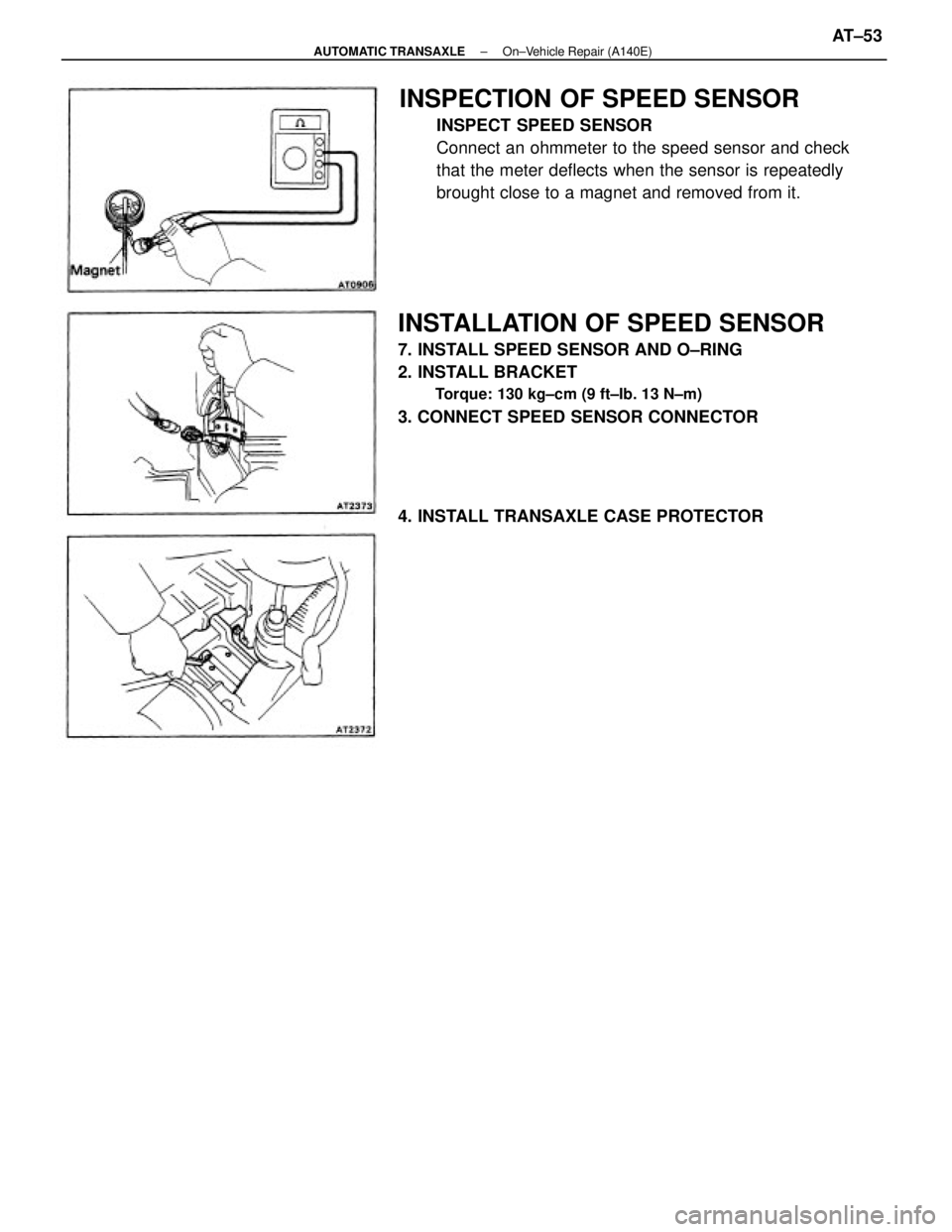
INSPECTION OF SPEED SENSOR
INSPECT SPEED SENSOR
Connect an ohmmeter to the speed sensor and check
that the meter deflects when the sensor is repeatedly
brought close to a magnet and removed from it.
INSTALLATION OF SPEED SENSOR
7. INSTALL SPEED SENSOR AND O±RING
2. INSTALL BRACKET
Torque: 130 kg±cm (9 ft±Ib. 13 N±m)
3. CONNECT SPEED SENSOR CONNECTOR
4. INSTALL TRANSAXLE CASE PROTECTOR
± AUTOMATIC TRANSAXLEOn±Vehicle Repair (A140E)AT±53
Page 309 of 2389
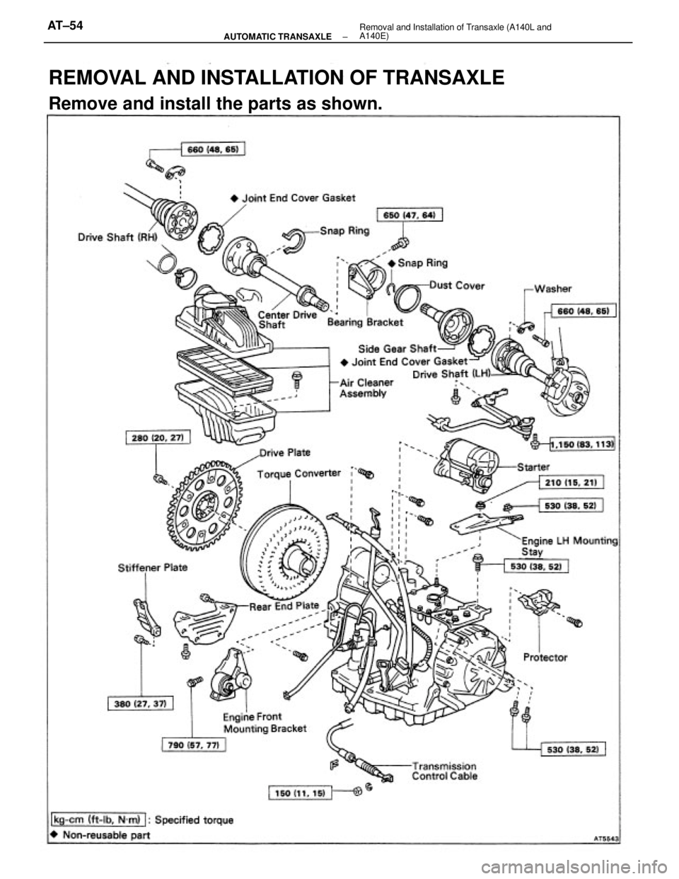
REMOVAL AND INSTALLATION OF TRANSAXLE
Remove and install the parts as shown.
± AUTOMATIC TRANSAXLERemoval and Installation of Transaxle (A140L and
A140E)AT±54
Page 310 of 2389
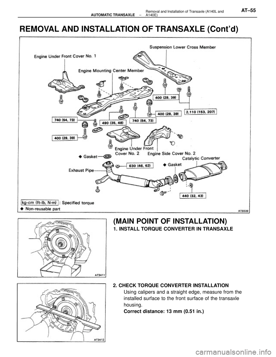
2. CHECK TORQUE CONVERTER INSTALLATION
Using calipers and a straight edge, measure from the
installed surface to the front surface of the transaxle
housing.
Correct distance: 13 mm (0.51 in.)
REMOVAL AND INSTALLATION OF TRANSAXLE (Cont'd)
(MAIN POINT OF INSTALLATION)
1. INSTALL TORQUE CONVERTER IN TRANSAXLE
± AUTOMATIC TRANSAXLERemoval and Installation of Transaxle (A140L and
A140E)AT±55