TOYOTA CAMRY V20 1986 Service Information
Manufacturer: TOYOTA, Model Year: 1986, Model line: CAMRY V20, Model: TOYOTA CAMRY V20 1986Pages: 2389, PDF Size: 84.44 MB
Page 811 of 2389
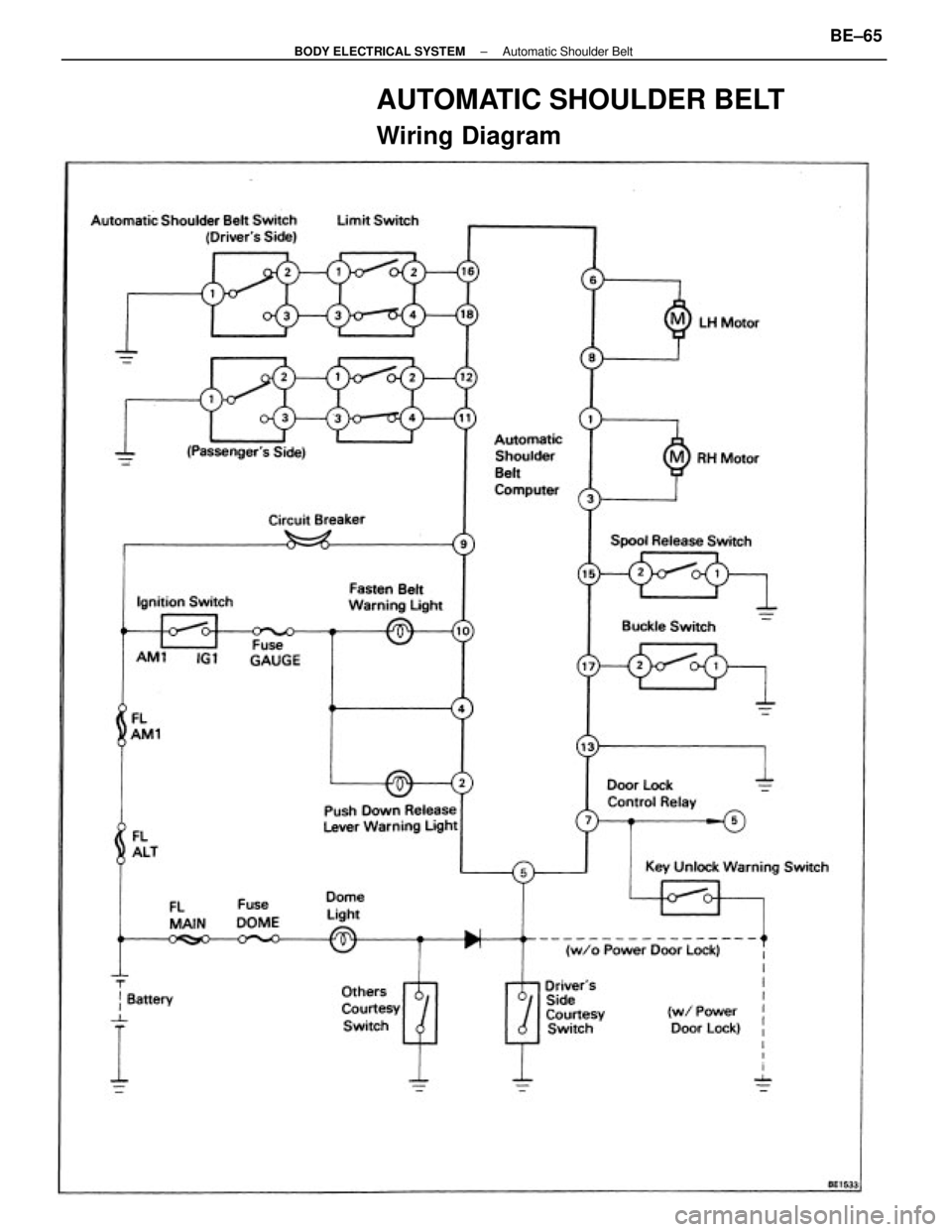
AUTOMATIC SHOULDER BELT
Wiring Diagram
± BODY ELECTRICAL SYSTEMAutomatic Shoulder BeltBE±65
Page 812 of 2389
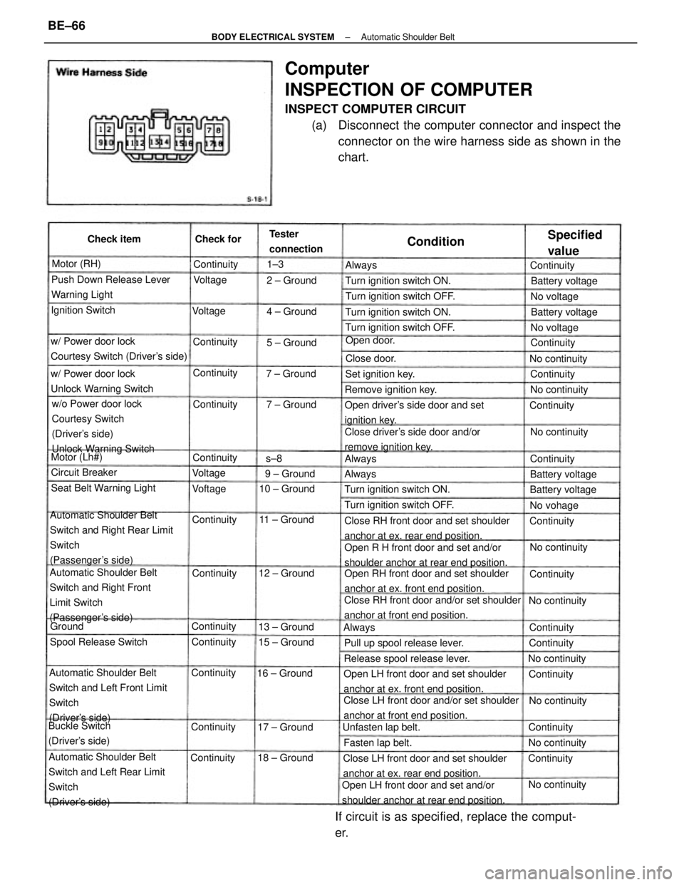
Computer
INSPECTION OF COMPUTER
INSPECT COMPUTER CIRCUIT
(a) Disconnect the computer connector and inspect the
connector on the wire harness side as shown in the
chart.
Automatic Shoulder Belt
Switch and Right Rear Limit
Switch
(Passenger's side)
Automatic Shoulder Belt
Switch and Left Front Limit
Switch
(Driver's side)
Automatic Shoulder Belt
Switch and Left Rear Limit
Switch
(Driver's side)Automatic Shoulder Belt
Switch and Right Front
Limit Switch
(Passenger's side)w/o Power door lock
Courtesy Switch
(Driver's side)
Unlock Warning Switch
Open RH front door and set shoulder
anchor at ex. front end position.
Close LH front door and/or set shoulder
anchor at front end position.Close RH front door and/or set shoulder
anchor at front end position.Close RH front door and set shoulder
anchor at ex. rear end position.
Open R H front door and set and/or
shoulder anchor at rear end position.
Open LH front door and set shoulder
anchor at ex. front end position.
Open LH front door and set and/or
shoulder anchor at rear end position.Close LH front door and set shoulder
anchor at ex. rear end position.
If circuit is as specified, replace the comput-
er.
Close driver's side door and/or
remove ignition key. Open driver's side door and set
ignition key. w/ Power door lock
Courtesy Switch (Driver's side)Push Down Release Lever
Warning Light
w/ Power door lock
Unlock Warning Switch
Release spool release lever.Pull up spool release lever.Turn ignition switch ON.
Seat Belt Warning LightTurn ignition switch OFF.
Turn ignition switch OFF.Turn ignition switch OFF.
Turn ignition switch ON.Turn ignition switch ON.
Buckle Switch
(Driver's side)Spool Release SwitchRemove ignition key. Tester
connection
Unfasten lap belt.
Specified
value
Set ignition key.
Battery voltage Ignition Switch
Battery voltage Battery voltage
Battery voltage
Fasten lap belt. Circuit Breaker
No continuity
No continuityNo continuity
No continuity No continuity
No continuity
No continuity
No continuity 15 ± Ground
No continuity 11 ± Ground 10 ± Ground
12 ± Ground
16 ± Ground
18 ± Ground13 ± Ground
17 ± GroundOpen door. Check item
7 ± Ground4 ± Ground
9 ± Ground7 ± Ground2 ± Ground
5 ± Ground Motor (RH)
Motor (Lh#)
Continuity
ContinuityNo voltage No voltage
No vohage Continuity
Continuity Continuity
ContinuityContinuity Continuity
Continuity
ContinuityContinuity Check for
Continuity ContinuityContinuity
Continuity Close door.
Continuity
ContinuityContinuityContinuity
ContinuityContinuity
Continuity
ContinuityContinuity
Condition
Voltage Voltage
VoftageVoltageAlways
AlwaysAlways
Always
Ground1±3
s±8
± BODY ELECTRICAL SYSTEMAutomatic Shoulder BeltBE±66
Page 813 of 2389
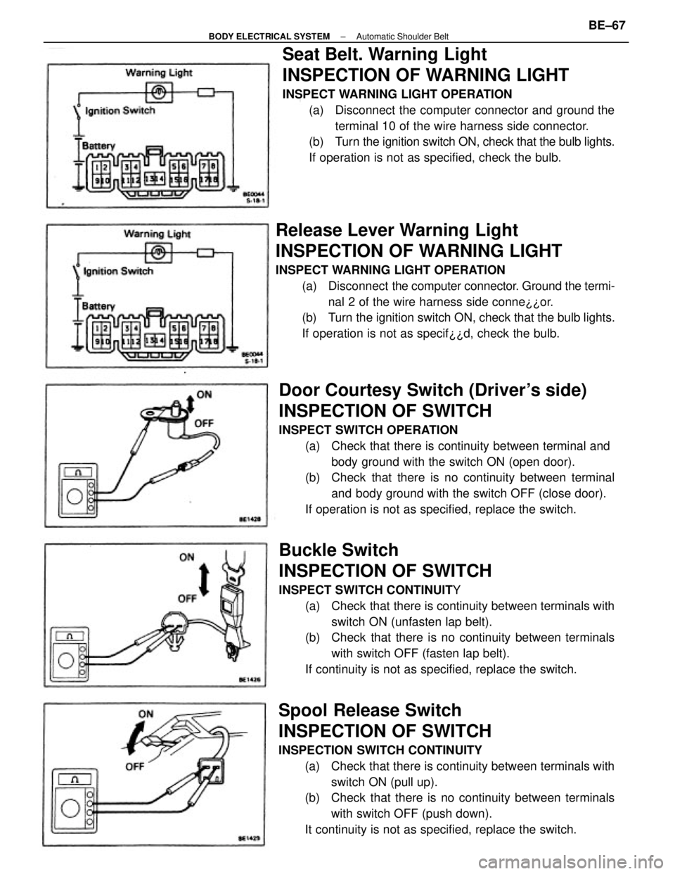
Seat Belt. Warning Light
INSPECTION OF WARNING LIGHT
INSPECT WARNING LIGHT OPERATION
(a) Disconnect the computer connector and ground the
terminal 10 of the wire harness side connector.
(b) Turn the ignition switch ON, check that the bulb lights.
If operation is not as specified, check the bulb.
Buckle Switch
INSPECTION OF SWITCH
INSPECT SWITCH CONTINUITY
(a) Check that there is continuity between terminals with
switch ON (unfasten lap belt).
(b) Check that there is no continuity between terminals
with switch OFF (fasten lap belt).
If continuity is not as specified, replace the switch.
Door Courtesy Switch (Driver's side)
INSPECTION OF SWITCH
INSPECT SWITCH OPERATION
(a) Check that there is continuity between terminal and
body ground with the switch ON (open door).
(b) Check that there is no continuity between terminal
and body ground with the switch OFF (close door).
If operation is not as specified, replace the switch.
Spool Release Switch
INSPECTION OF SWITCH
INSPECTION SWITCH CONTINUITY
(a) Check that there is continuity between terminals with
switch ON (pull up).
(b) Check that there is no continuity between terminals
with switch OFF (push down).
It continuity is not as specified, replace the switch.
Release Lever Warning Light
INSPECTION OF WARNING LIGHT
INSPECT WARNING LIGHT OPERATION
(a) Disconnect the computer connector. Ground the termi-
nal 2 of the wire harness side conne¿¿or.
(b) Turn the ignition switch ON, check that the bulb lights.
If operation is not as specif¿¿d, check the bulb.
± BODY ELECTRICAL SYSTEMAutomatic Shoulder BeltBE±67
Page 814 of 2389
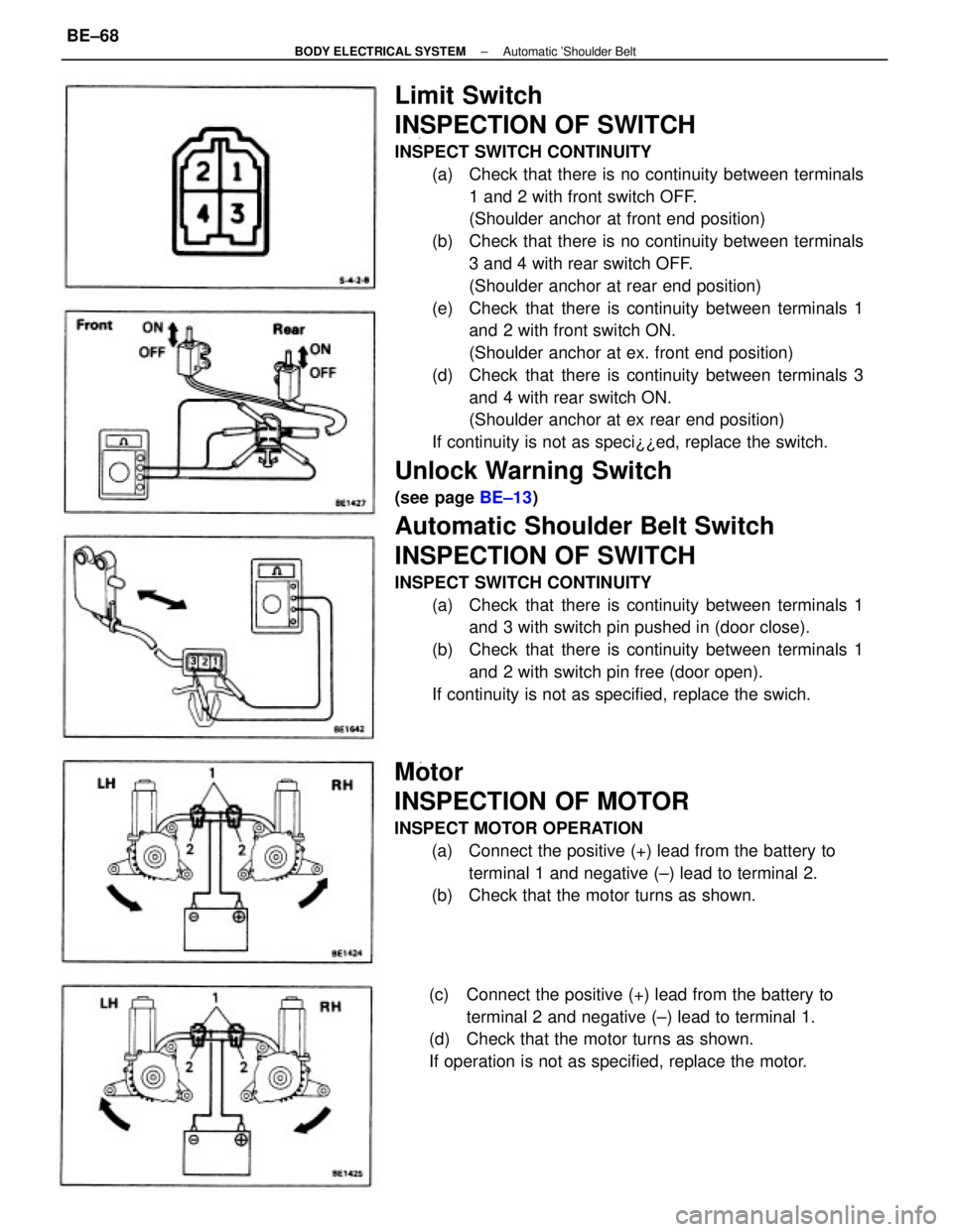
Limit Switch
INSPECTION OF SWITCH
INSPECT SWITCH CONTINUITY
(a) Check that there is no continuity between terminals
1 and 2 with front switch OFF.
(Shoulder anchor at front end position)
(b) Check that there is no continuity between terminals
3 and 4 with rear switch OFF.
(Shoulder anchor at rear end position)
(e) Check that there is continuity between terminals 1
and 2 with front switch ON.
(Shoulder anchor at ex. front end position)
(d) Check that there is continuity between terminals 3
and 4 with rear switch ON.
(Shoulder anchor at ex rear end position)
If continuity is not as speci¿¿ed, replace the switch.
Unlock Warning Switch
(see page BE±13)
Automatic Shoulder Belt Switch
INSPECTION OF SWITCH
INSPECT SWITCH CONTINUITY
(a) Check that there is continuity between terminals 1
and 3 with switch pin pushed in (door close).
(b) Check that there is continuity between terminals 1
and 2 with switch pin free (door open).
If continuity is not as specified, replace the swich.
Motor
INSPECTION OF MOTOR
INSPECT MOTOR OPERATION
(a) Connect the positive (+) lead from the battery to
terminal 1 and negative (±) lead to terminal 2.
(b) Check that the motor turns as shown.
(c) Connect the positive (+) lead from the battery to
terminal 2 and negative (±) lead to terminal 1.
(d) Check that the motor turns as shown.
If operation is not as specified, replace the motor.
± BODY ELECTRICAL SYSTEMAutomatic 'Shoulder BeltBE±68
Page 815 of 2389
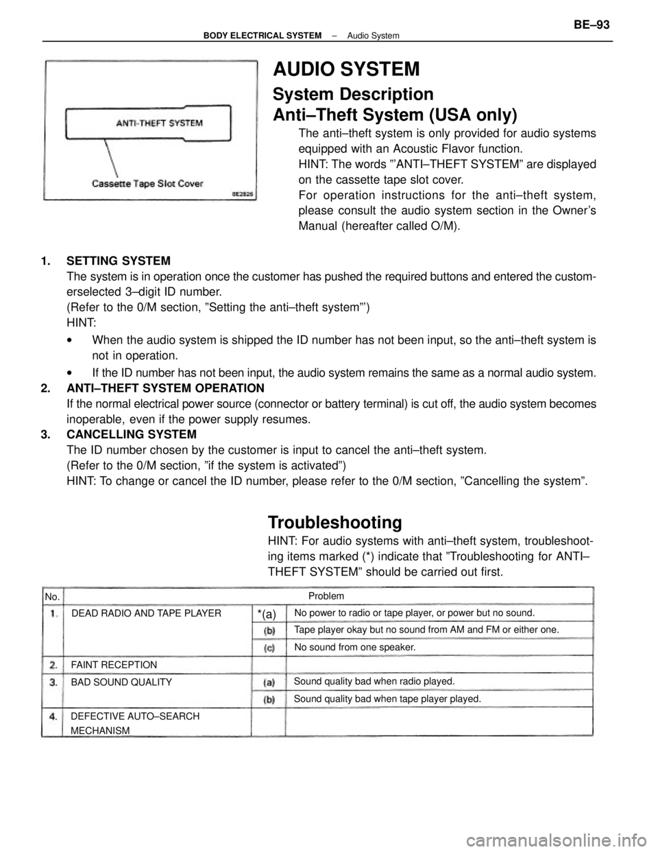
1. SETTING SYSTEM
The system is in operation once the customer has pushed the required buttons and entered the custom-
erselected 3±digit ID number.
(Refer to the 0/M section, ºSetting the anti±theft systemº')
HINT:
wWhen the audio system is shipped the ID number has not been input, so the anti±theft system is
not in operation.
wIf the ID number has not been input, the audio system remains the same as a normal audio system.
2. ANTI±THEFT SYSTEM OPERATION
If the normal electrical power source (connector or battery terminal) is cut off, the audio system becomes
inoperable, even if the power supply resumes.
3. CANCELLING SYSTEM
The ID number chosen by the customer is input to cancel the anti±theft system.
(Refer to the 0/M section, ºif the system is activatedº)
HINT: To change or cancel the ID number, please refer to the 0/M section, ºCancelling the systemº.
AUDIO SYSTEM
System Description
Anti±Theft System (USA only)
The anti±theft system is only provided for audio systems
equipped with an Acoustic Flavor function.
HINT: The words º'ANTI±THEFT SYSTEMº are displayed
on the cassette tape slot cover.
For operation instructions for the anti±theft system,
please consult the audio system section in the Owner's
Manual (hereafter called O/M).
Tape player okay but no sound from AM and FM or either one.No power to radio or tape player, or power but no sound.
Sound quality bad when tape player played.
DEFECTIVE AUTO±SEARCH
MECHANISMSound quality bad when radio played. DEAD RADIO AND TAPE PLAYER
No sound from one speaker.
BAD SOUND QUALITY FAINT RECEPTIONProblem
*(a)
No.
Troubleshooting
HINT: For audio systems with anti±theft system, troubleshoot-
ing items marked (*) indicate that ºTroubleshooting for ANTI±
THEFT SYSTEMº should be carried out first.
± BODY ELECTRICAL SYSTEMAudio SystemBE±93
Page 816 of 2389
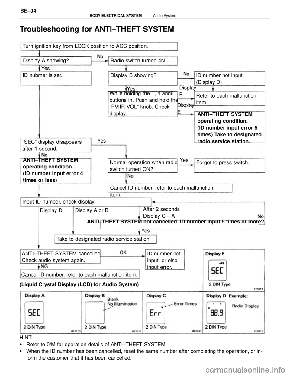
HINT:
wRefer to 0/M for operation details of ANTI±THEFT SYSTEM.
wWhen the ID number has been cancelled, reset the same number after completing the operation, or in-
form the customer that it has been cancelled.ANTI±THEFT SYSTEM
operating condition.
(ID number input error 5
times) Take to designated
radio service station. While holding the 1, 4 and6
buttons in. Push and hold the
ºPVIIR VOLº knob. Check
display.
ANTI±THEFT SYSTEM
operating condition.
(ID number input error 4
times or less)
ANTI±THEFT SYSTEM not cancelled. ID number input 5 times or more?
Troubleshooting for ANTI±THEFT SYSTEM
Turn ignition key from LOCK position to ACC position.
ANTI±THEFT SYSTEM cancelled.
Check audio system again.
(Liquid Crystal Display (LCD) for Audio System)Cancel ID number, refer to each malfunction item.Cancel ID number, refer to each malfunction
item. Normal operation when radio
switch turned ON?
Take to designated radio service station.Refer to each malfunction
item.
ºSECº display disappears
after 1 second.ID number not input.
(Display D)
ID number not
input, or else
input error. After 2 seconds
Display C ± A Input ID number, check display.Forgot to press switch. Radio switch turned 4N. Display A showing?
Display B showing? ID nubmer is set.
Display A or BDisplay
EDisplay
B
Display DYe s
Ye sYe s Ye s
Ye s
± BODY ELECTRICAL SYSTEMAudio SystemBE±94
Page 817 of 2389
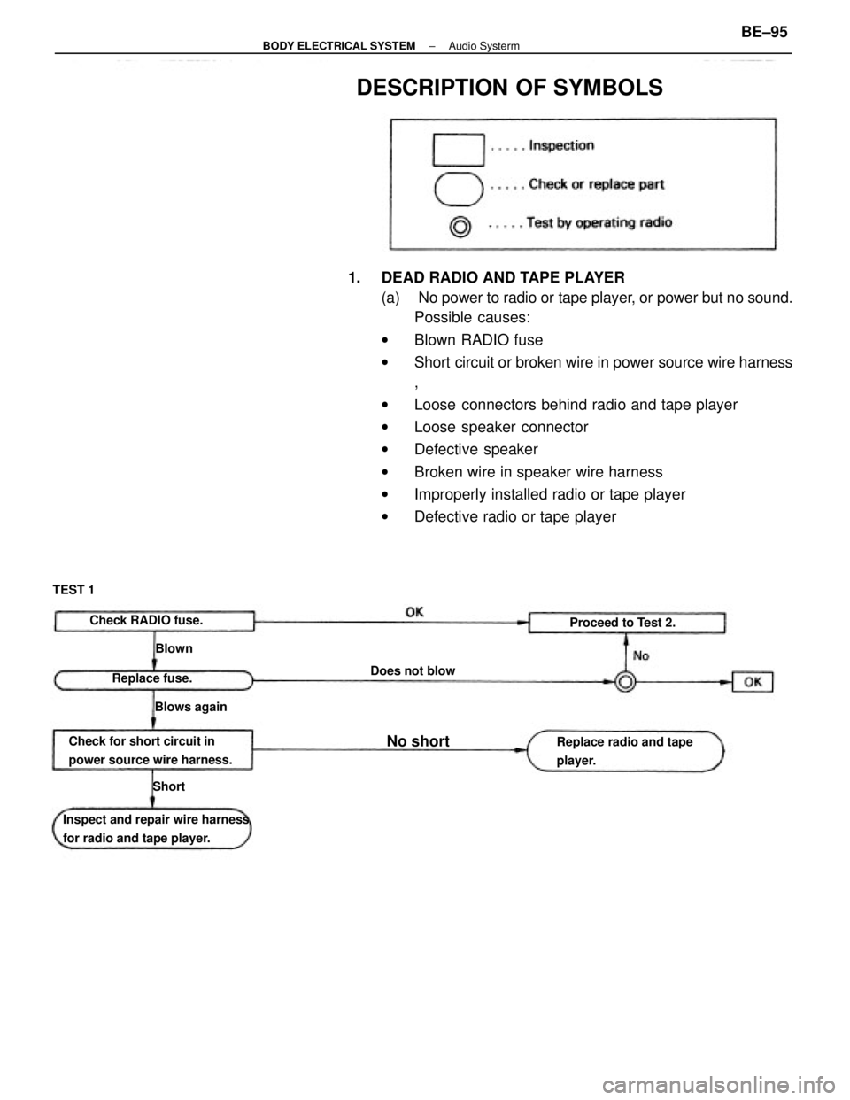
1. DEAD RADIO AND TAPE PLAYER
(a) No power to radio or tape player, or power but no sound.
Possible causes:
wBlown RADIO fuse
wShort circuit or broken wire in power source wire harness
,
wLoose connectors behind radio and tape player
wLoose speaker connector
wDefective speaker
wBroken wire in speaker wire harness
wImproperly installed radio or tape player
wDefective radio or tape player
Inspect and repair wire harness
for radio and tape player.Check for short circuit in
power source wire harness.
DESCRIPTION OF SYMBOLS
Replace radio and tape
player. Check RADIO fuse.
Proceed to Test 2.
Does not blow
Replace fuse.
Blows again TEST 1No short
Blown
Short
± BODY ELECTRICAL SYSTEMAudio SystermBE±95
Page 818 of 2389
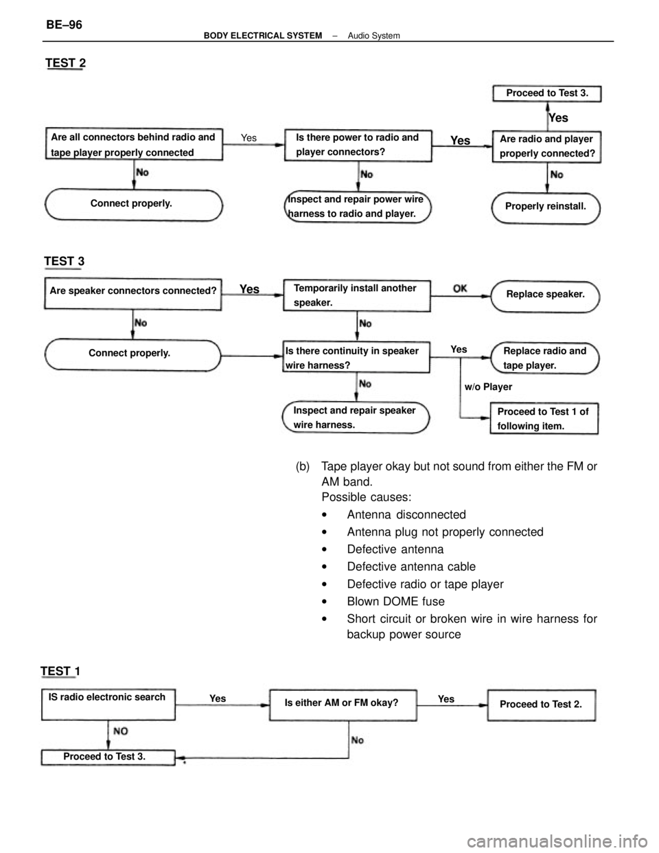
(b) Tape player okay but not sound from either the FM or
AM band.
Possible causes:
wAntenna disconnected
wAntenna plug not properly connected
wDefective antenna
wDefective antenna cable
wDefective radio or tape player
wBlown DOME fuse
wShort circuit or broken wire in wire harness for
backup power source
Are all connectors behind radio and
tape player properly connected
Is there continuity in speaker
wire harness?Inspect and repair power wire
harness to radio and player.
Temporarily install another
speaker.Is there power to radio and
player connectors?
Inspect and repair speaker
wire harness.
IS radio electronic searchAre speaker connectors connected?Are radio and player
properly connected?
Proceed to Test 1 of
following item.Replace radio and
tape player.
Is either AM or FM okay? Connect properly.Properly reinstall. Connect properly.
Proceed to Test 3.Replace speaker. Proceed to Test 3.
Proceed to Test 2. w/o PlayerYe s TEST 2
TEST 3
TEST 1
Ye s
Ye s
Ye s
Ye s
Ye s Ye s
± BODY ELECTRICAL SYSTEMAudio SystemBE±96
Page 819 of 2389
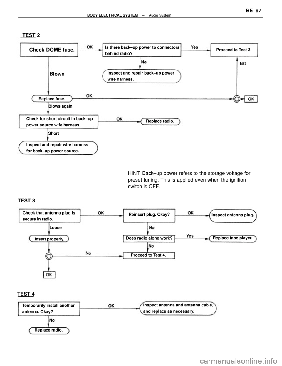
HINT: Back±up power refers to the storage voltage for
preset tuning. This is applied even when the ignition
switch is OFF.
Is there back±up power to connectors
behind radio?
Inspect antenna and antenna cable,
and replace as necessary. Check for short circuit in back±up
power source wife harness.Inspect and repair back±up power
wire harness.
Inspect and repair wire harness
for back±up power source.
Temporarily install another
antenna. Okay?Check that antenna plug is
secure in radio.Inspect antenna plug.
Does radio alone work?Reinsert plug. Okay?
Replace tape player.Check DOME fuse.Proceed to Test 3.
Proceed to Test 4. Insert properly.
Replace radio.Replace fuse.
Replace radio. Blows again
TEST 3
TEST 4TEST 2
Blown
Loose Short
Ye sYe s
± BODY ELECTRICAL SYSTEMAudio SystemBE±97
Page 820 of 2389
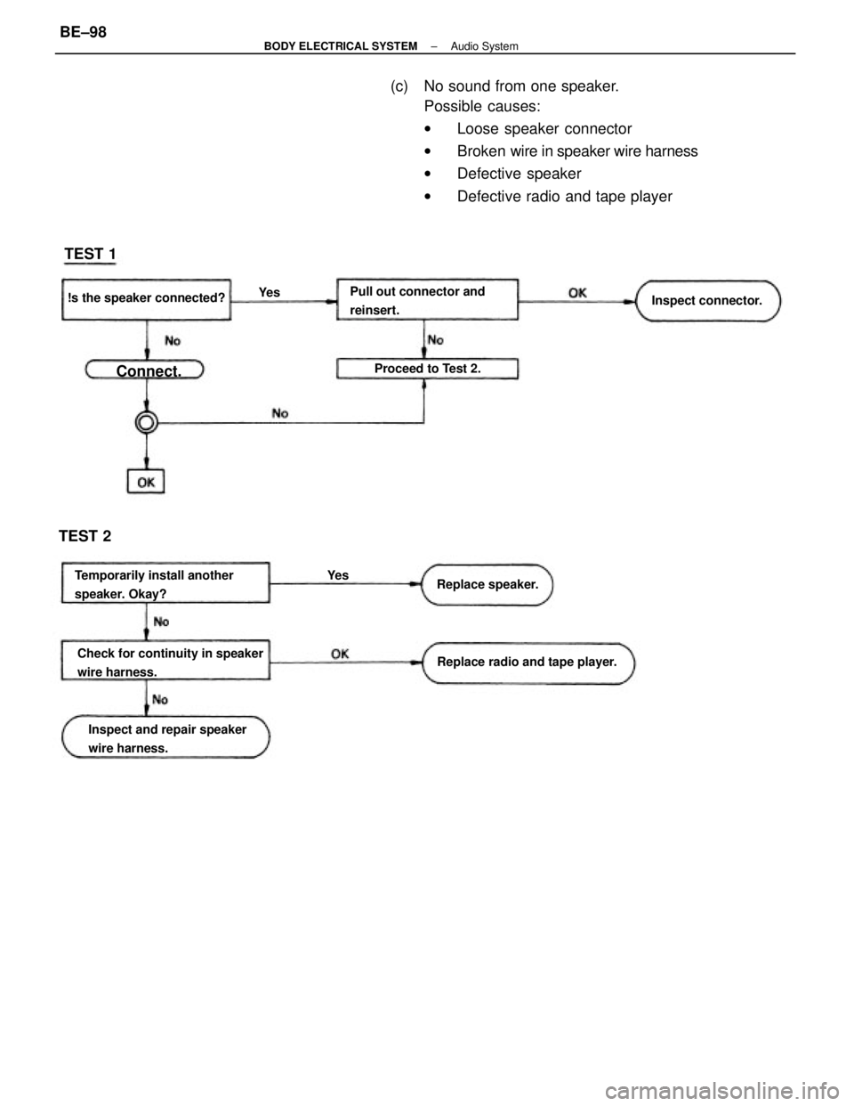
(c) No sound from one speaker.
Possible causes:
wLoose speaker connector
wBroken wire in speaker wire harness
wDefective speaker
wDefective radio and tape player
Pull out connector and
reinsert.
Check for continuity in speaker
wire harness. Temporarily install another
speaker. Okay?
Inspect and repair speaker
wire harness.Replace radio and tape player. !s the speaker connected?
Inspect connector.
Proceed to Test 2.
Replace speaker.
TEST 2TEST 1
Connect.
Ye s
Ye s
± BODY ELECTRICAL SYSTEMAudio SystemBE±98