TOYOTA CAMRY V20 1986 Service Information
Manufacturer: TOYOTA, Model Year: 1986, Model line: CAMRY V20, Model: TOYOTA CAMRY V20 1986Pages: 2389, PDF Size: 84.44 MB
Page 851 of 2389

BRAKE SYSTEM
± BRAKE SYSTEMBR±1
Page 852 of 2389
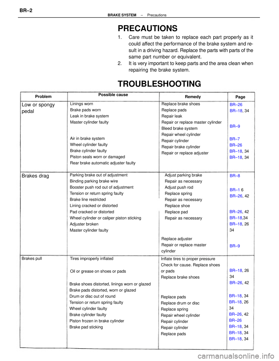
PRECAUTIONS
1. Care must be taken to replace each part properly as it
could affect the performance of the brake system and re-
sult in a driving hazard. Replace the parts with parts of the
same part number or equivalent.
2. It is very important to keep parts and the area clean when
repairing the brake system.
Parking brake out of adjustment
Binding parking brake wire
Booster push rod out of adjustment
Tension or return spring faulty
Brake line restricted
Lining cracked or distorted
Pad cracked or distorted
Wheel cylinder or caliper piston sticking
Adjuster broken
Master cylinder faulty
Brake shoes distorted, linings worn or glazed
Brake pads distorted, worn or glazed
Drum or disc out of round
Tension or return spring faulty
Wheel cylinder faulty
Brake cylinder faulty
Piston frozen in brake cylinder
Brake pad stickingReplace brake shoes
Replace pads
Repair leak
Repair or replace master cylinder
Bleed brake system
Repair wheel cylinder
Repair cylinder
Repair brake cylinder
Repair or replace adjuster Air in brake system
Wheel cylinder faulty
Brake cylinder faulty
Piston seals worn or damaged
Rear brake automatic adjuster faulty
Adjust parking brake
Repair as necessary
Adjust push rod
Replace spring
Repair as necessary
Replace shoe
Replace pad
Repair as necessary
Replace pads
Replace drum or disc
Replace spring
Repair wheel cylinder
Repair cylinder
Repair cylinder
Replace padsInflate tires to proper pressure
Check for cause. Replace shoes
or pads
Replace brake shoes Linings worn
Brake pads worn
Leak in brake system
Master cylinder faulty
BR±18, 34
BR±18, 26
34
BR±26, 42
BR±26
BR±18, 34
BR±18, 34
BR±18, 34 Replace adjuster
Repair or replace master
cylinder
TROUBLESHOOTING
BR±7
BR±26
BR±18, 34
BR±18, 34
BR±26, 42
BR±18,34
BR±18, 26
34
Oil or grease on shoes or pads Tires improperly inflated
BR±18, 26
34
BR±26, 42
Low or spongy
pedalBR±26
BR±18, 34
BR±1 6
BR±26, 42 Possible cause
Brakes drag
Brakes pullRemedy Problem
Page
BR±8
BR±9BR±9
± BRAKE SYSTEMPrecautionsBR±2
Page 853 of 2389
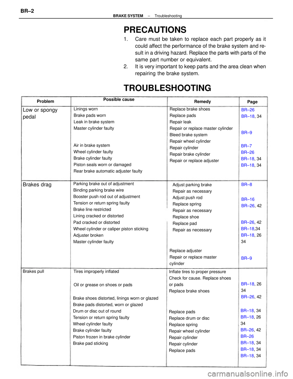
PRECAUTIONS
1. Care must be taken to replace each part properly as it
could affect the performance of the brake system and re-
sult in a driving hazard. Replace the parts with parts of the
same part number or equivalent.
2. It is very important to keep parts and the area clean when
repairing the brake system.
Parking brake out of adjustment
Binding parking brake wire
Booster push rod out of adjustment
Tension or return spring faulty
Brake line restricted
Lining cracked or distorted
Pad cracked or distorted
Wheel cylinder or caliper piston sticking
Adjuster broken
Master cylinder faulty
Brake shoes distorted, linings worn or glazed
Brake pads distorted, worn or glazed
Drum or disc out of round
Tension or return spring faulty
Wheel cylinder faulty
Brake cylinder faulty
Piston frozen in brake cylinder
Brake pad stickingReplace brake shoes
Replace pads
Repair leak
Repair or replace master cylinder
Bleed brake system
Repair wheel cylinder
Repair cylinder
Repair brake cylinder
Repair or replace adjuster Air in brake system
Wheel cylinder faulty
Brake cylinder faulty
Piston seals worn or damaged
Rear brake automatic adjuster faulty
Adjust parking brake
Repair as necessary
Adjust push rod
Replace spring
Repair as necessary
Replace shoe
Replace pad
Repair as necessary
Replace pads
Replace drum or disc
Replace spring
Repair wheel cylinder
Repair cylinder
Repair cylinder
Replace padsInflate tires to proper pressure
Check for cause. Replace shoes
or pads
Replace brake shoes Linings worn
Brake pads worn
Leak in brake system
Master cylinder faulty
BR±18, 34
BR±18, 26
34
BR±26, 42
BR±26
BR±18, 34
BR±18, 34
BR±18, 34 Replace adjuster
Repair or replace master
cylinder
TROUBLESHOOTING
BR±7
BR±26
BR±18, 34
BR±18, 34
BR±26, 42
BR±18,34
BR±18, 26
34
Oil or grease on shoes or pads Tires improperly inflated
BR±18, 26
34
BR±26, 42
Low or spongy
pedalBR±26
BR±18, 34
BR±16
BR±26, 42 Possible cause
Brakes drag
Brakes pullRemedy Problem
Page
BR±8
BR±9BR±9
± BRAKE SYSTEMTroubleshootingBR±2
Page 854 of 2389
(Drum brake)
Brake shoes binding at backing plate ledges
Backing plate ledges worn
Loose or missing shoe hold±down spring
Loose set bolt at backing plate
(Disc brake)
Loose or missing pad support plate
Loose installation bolt
Wear on slide bushingBrake shoes distorted, linings worn or glazed,
drums worn
Brake pads distorted, worn or glazed
Piston frozen in brake cylinder
Brake booster faulty
Vacuum leaks
Brake line restricted
Caliper to wheel or rotor interference
Dust cover to rotor or backing plate to drum
interference
Other brake system components faultyReplace and lubricate ledges
Replace shoe hold±down spring
TightenReplace pads
Repair cylinder
Repair booster
Repair as necessary
Repair as necessary
Replace pad support plate
Tighten
Replace slide bushing
Replace or refinish drums or rotors if
heavily scored
Replace as required
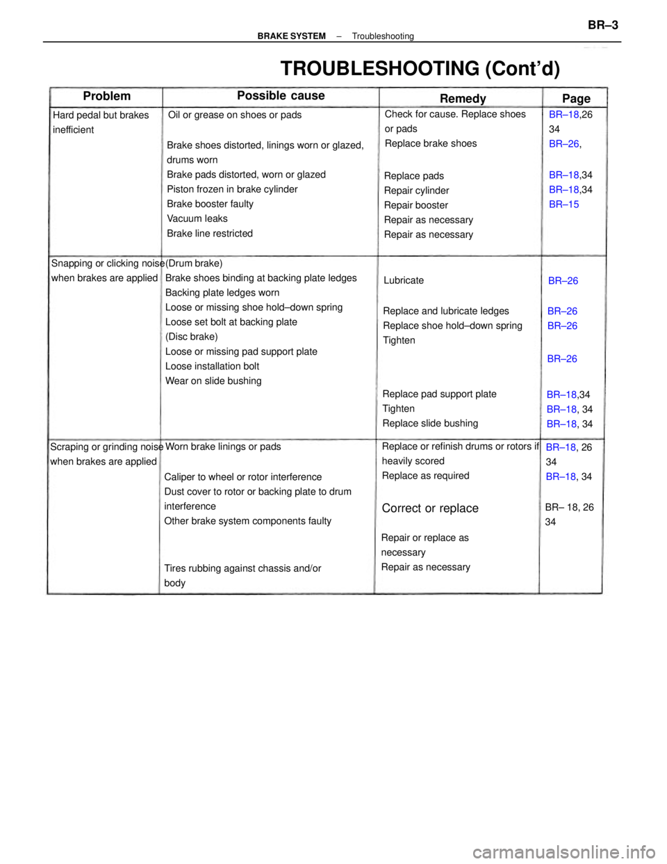
TROUBLESHOOTING (Cont'd)
Check for cause. Replace shoes
or pads
Replace brake shoes
Repair or replace as
necessary
Repair as necessary
Tires rubbing against chassis and/or
body Snapping or clicking noise
when brakes are applied
Scraping or grinding noise
when brakes are appliedOil or grease on shoes or pads
Hard pedal but brakes
inefficient
Worn brake linings or padsBR±18,34
BR±18, 34
BR±18, 34 BR±18,34
BR±18,34
BR±15 BR±18,26
34
BR±26,
BR±18, 26
34
BR±18, 34
Correct or replaceBR± 18, 26
34
Possible cause
BR±26
BR±26 Lubricate
Problem
Remedy
BR±26
Page
BR±26
± BRAKE SYSTEMTroubleshootingBR±3
Page 855 of 2389
Maladjustment of brake pedal or booster push
rod
Poor return of brake booster or master cylinder or
wheel cylinder
(Disc brake)
Rusted or stuck piston
Improper positioning of pad in caliper
Rotor rubbing against caliper housing
Improper installation of disc brake pad support
plate
Pad wear and pad wear indicator making contact
with the rotor
(Drum brake)
Weak, damaged or incorrect shoe hold±down
springs
Grooved backing plate ledges
Bent or warped backing plate causing
interference with drum
Improper machining of drum causing interference
with backing plate or shoe
Other brake system components:
Loose or extra parts in brakes
Rear drum adjustment too tight causing lining to
glaze
Worn, damaged or insufficiently lubricated wheel
bearings Brake drums and linings, rotors and pads
worn or scored
Dirty, greased, contaminated or glazed
linings or pads
Improper linings or pads using
Maladjustment of brake pedal or booster
push rod
(Disc brake)
Missing or damaged brake pad
anti±squeal shim
Pad wear and pad wear indicator making
contact with the rotor
Burred or rusted calipers
(Drum brake)
Weak damaged or incorrect shoe
hold±down springs, loose or damaged
shoe hold±down spring pins and springs
and grooved backing plate ledges Squeaking, squealing
groaning or chattering
noise when brakes are
applied
Note: Brake friction
materials inherently
generate noise and heat in
order to dissipate eniergy.
As a result, occasional
squeal is normal and is
aggravated by severe
environmental conditions
such as cold,' heat,
wetness, snow, salt, mud,
etc. This occasional squeal
is not a functional problem
and does not indicate any
loss of brake effectivenessInspect, repair or replace
Clean or replace
Inspect for correct usage or
replace
Inspect and adjust
Inspect and lubricate as
necessary
Repair or replace
Repair or replace
Repair or replace
Replace
Replace
Repair or replace
Repair or replace
Replace drum
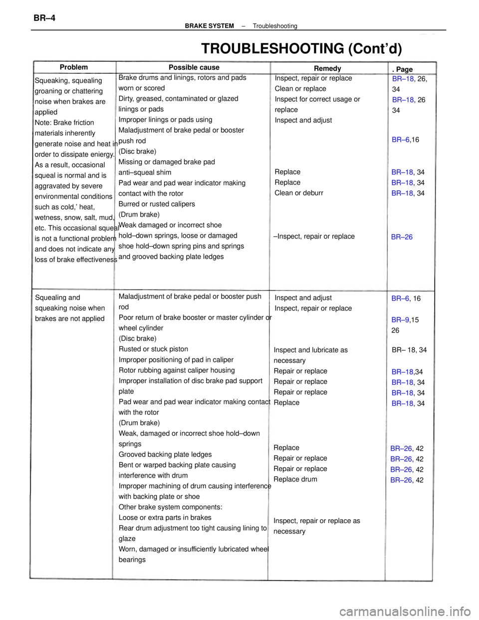
TROUBLESHOOTING (Cont'd)
Replace
Replace
Clean or deburr
Inspect and adjust
Inspect, repair or replace Squealing and
squeaking noise when
brakes are not applied
BR±26, 42
BR±26, 42
BR±26, 42
BR±26, 42 BR±18,34
BR±18, 34
BR±18, 34
BR±18, 34
Inspect, repair or replace as
necessaryBR±18, 34
BR±18, 34
BR±18, 34 BR±18, 26,
34
BR±18, 26
34
±Inspect, repair or replace
BR±9,15
26 Possible cause
BR± 18, 34 BR±6,16 . Page Remedy
BR±6, 16 Problem
BR±26
± BRAKE SYSTEMTroubleshootingBR±4
Page 856 of 2389
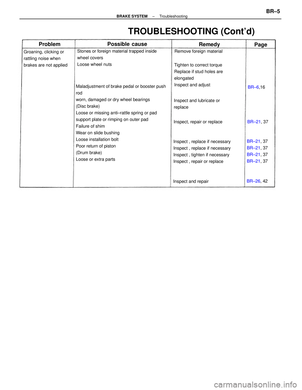
Maladjustment of brake pedal or booster push
rod
worn, damaged or dry wheel bearings
(Disc brake)
Loose or missing anti±rattle spring or pad
support plate or rimping on outer pad
Failure of shim
Wear on slide bushing
Loose installation bolt
Poor return of piston
(Drum brake)
Loose or extra partsInspect , replace if necessary
Inspect , replace if necessary
Inspect , tighten if necessary
Inspect , repair or replaceTighten to correct torque
Replace if stud holes are
elongated
Inspect and adjust Stones or foreign material trapped inside
wheel covers
Loose wheel nuts
TROUBLESHOOTING (Cont'd)
Groaning, clicking or
rattling noise when
brakes are not applied
Inspect and lubricate or
replace
BR±21, 37
BR±21, 37
BR±21, 37
BR±21, 37 Inspect, repair or replaceRemove foreign material
Inspect and repair
Possible cause
BR±21, 37
BR±26, 42 BR±6,16
Problem
Remedy
Page
± BRAKE SYSTEMTroubleshootingBR±5
Page 857 of 2389
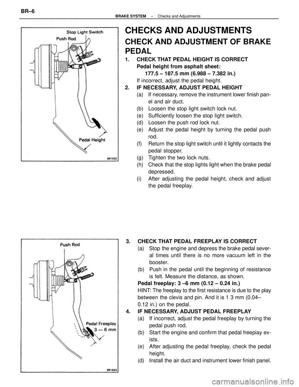
CHECKS AND ADJUSTMENTS
CHECK AND ADJUSTMENT OF BRAKE
PEDAL
1. CHECK THAT PEDAL HEIGHT IS CORRECT
Pedal height from asphalt sheet:
177.5 ± 187.5 mm (6.988 ± 7.382 in.)
If incorrect, adjust the pedal height.
2. IF NECESSARY, ADJUST PEDAL HEIGHT
(a) If necessary, remove the instrument lower finish pan-
el and air duct.
(b) Loosen the stop light switch lock nut.
(e) Sufficiently loosen the stop light switch.
(d) Loosen the push rod lock nut.
(e) Adjust the pedal height by turning the pedal push
rod.
(f) Return the stop light switch until it lightly contacts the
pedal stopper.
(g) Tighten the two lock nuts.
(h) Check that the stop lights light when the brake pedal
depressed.
(i) After adjusting the pedal height, check and adjust
the pedal freeplay.
3. CHECK THAT PEDAL FREEPLAY IS CORRECT
(a) Stop the engine and depress the brake pedal sever-
al times until there is no more vacuum left in the
booster.
(b) Push in the pedal until the beginning of resistance
is felt. Measure the distance, as shown.
Pedal freeplay: 3 ±6 mm (0.12 ± 0.24 in.)
HINT: The freeplay to the first resistance is due to the play
between the clevis and pin. And it is 1 3 mm (0.04±
0.12 in.) on the pedal.
4. IF NECESSARY, ADJUST PEDAL FREEPLAY
(a) If incorrect, adjust the pedal freeplay by turning the
pedal push rod.
(b) Start the engine and confirm that pedal freepiay ex-
ists.
(e) After adjusting the pedal freeplay, check the pedal
height.
(d) Install the air duct and instrument lower finish panel.
± BRAKE SYSTEMChecks and AdjustmentsBR±6
Page 858 of 2389

OPERATIONAL TEST OF BRAKE
BOOSTER
HINT: If there is leakage or lack of vacuum, repair before
testing. If available, use a brake booster tester to check the
booster operating condition.
1. OPERATING CHECK
(a) Depress the brake pedal several times with the en-
gine stopped, and check that is no change in the ped-
al reserve distance.
(b) Depress the brake pedal and start the engine. If the
pedal goes down slightly, operation is normal.
2. AIR TIGHTNESS CHECK
(a) Start the engine and stop it after one or two minutes.
Depress the brake pedal several times slowly. If the
pedal goes down furtherest the first time, but gradual-
ly rises after the second or third time, the booster is air
tight.
(b) Depress the brake pedal while the engine is running,
and stop it with the pedal depressed. If there is no
change in pedal reserve travel after holding the pedal
for thirty seconds, the booster is air tight.
BLEEDING OF BRAKE SYSTEM
HINT: If any work is done on the brake system or if air is sus-
pected in the brake lines, bleed the system of air.
NOTICE: Do not let brake fluid remain on a painted surface.
Wash it off immediately.
1. FILL BRAKE RESERVOIR WITH BRAKE FLUID
Check the fluid level in the reservoir. If necessary, add
brake fluid. 5. CHECK THAT PEDAL RESERVE DISTANCE IS
CORRECT
Release the parking brake. With engine running, depress
the pedal and measure the pedal reserve distance, as
shown.
Pedal reserve distance from asphalt sheet at 50 kg
(110.2 1b): More than 85 mm, (3.35 in.)
If incorrect, troubleshoot the brake system.
2. BLEED MASTER CYLINDER
HINT: If the master cylinder was disassembled or if the res-
ervoir becomes empty, bleed the air from the master cylin-
der.
(a) Disconnect the brake tubes from the master cylinder.
(b) Depress the brake pedal and hold it.
± BRAKE SYSTEMChecks and AdjustmentsBR±7
Page 859 of 2389
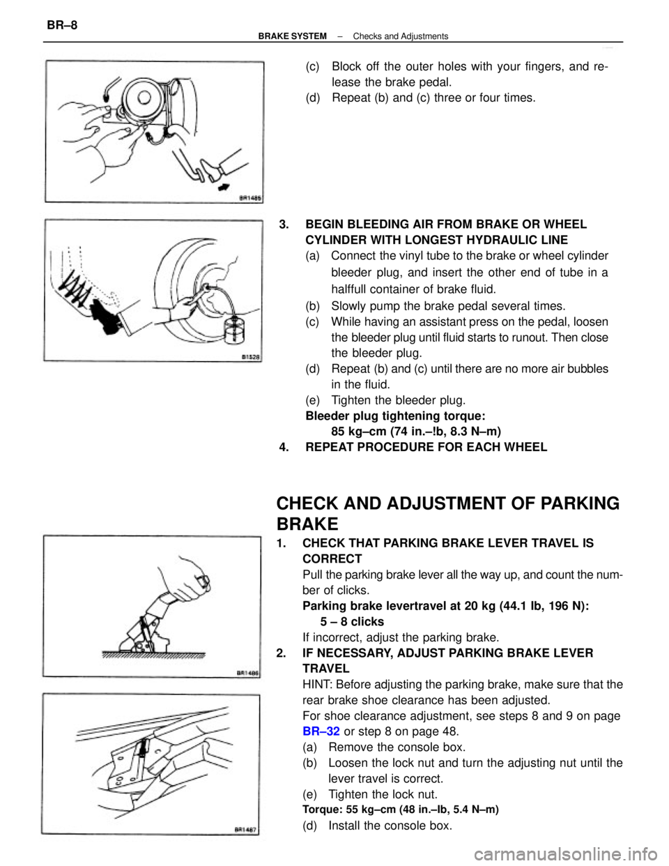
CHECK AND ADJUSTMENT OF PARKING
BRAKE
1. CHECK THAT PARKING BRAKE LEVER TRAVEL IS
CORRECT
Pull the parking brake lever all the way up, and count the num-
ber of clicks.
Parking brake levertravel at 20 kg (44.1 Ib, 196 N):
5 ± 8 clicks
If incorrect, adjust the parking brake.
2. IF NECESSARY, ADJUST PARKING BRAKE LEVER
TRAVEL
HINT: Before adjusting the parking brake, make sure that the
rear brake shoe clearance has been adjusted.
For shoe clearance adjustment, see steps 8 and 9 on page
BR±32 or step 8 on page 48.
(a) Remove the console box.
(b) Loosen the lock nut and turn the adjusting nut until the
lever travel is correct.
(e) Tighten the lock nut.
Torque: 55 kg±cm (48 in.±Ib, 5.4 N±m)
(d) Install the console box. 3. BEGIN BLEEDING AIR FROM BRAKE OR WHEEL
CYLINDER WITH LONGEST HYDRAULIC LINE
(a) Connect the vinyl tube to the brake or wheel cylinder
bleeder plug, and insert the other end of tube in a
halffull container of brake fluid.
(b) Slowly pump the brake pedal several times.
(c) While having an assistant press on the pedal, loosen
the bleeder plug until fluid starts to runout. Then close
the bleeder plug.
(d) Repeat (b) and (c) until there are no more air bubbles
in the fluid.
(e) Tighten the bleeder plug.
Bleeder plug tightening torque:
85 kg±cm (74 in.±!b, 8.3 N±m)
4. REPEAT PROCEDURE FOR EACH WHEEL(c) Block off the outer holes with your fingers, and re-
lease the brake pedal.
(d) Repeat (b) and (c) three or four times.
± BRAKE SYSTEMChecks and AdjustmentsBR±8
Page 860 of 2389
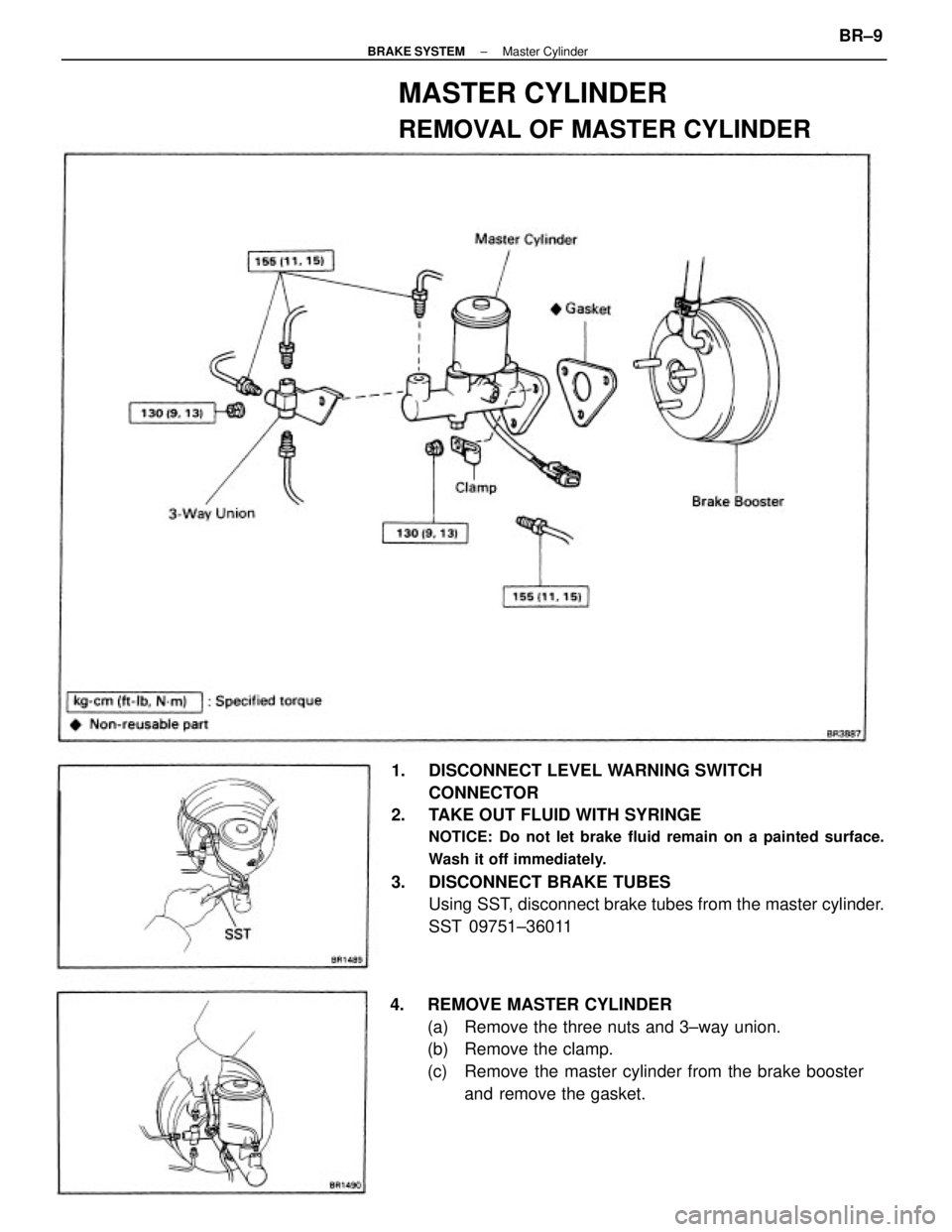
1. DISCONNECT LEVEL WARNING SWITCH
CONNECTOR
2. TAKE OUT FLUID WITH SYRINGE
NOTICE: Do not let brake fluid remain on a painted surface.
Wash it off immediately.
3. DISCONNECT BRAKE TUBES
Using SST, disconnect brake tubes from the master cylinder.
SST 09751±36011
4. REMOVE MASTER CYLINDER
(a) Remove the three nuts and 3±way union.
(b) Remove the clamp.
(c) Remove the master cylinder from the brake booster
and remove the gasket.
MASTER CYLINDER
REMOVAL OF MASTER CYLINDER
± BRAKE SYSTEMMaster CylinderBR±9