TOYOTA CAMRY V20 1986 Service Information
Manufacturer: TOYOTA, Model Year: 1986, Model line: CAMRY V20, Model: TOYOTA CAMRY V20 1986Pages: 2389, PDF Size: 84.44 MB
Page 801 of 2389
Power Window Motor
INSPECTION OF MOTOR
1. INSPECT CIRCUIT BREAKER OPERATION
(a) With the window in the full closed position, hold the
power window switch in ┬║UP┬║ position and check that
there is a circuit breaker operation noise within 4 to 40
seconds.
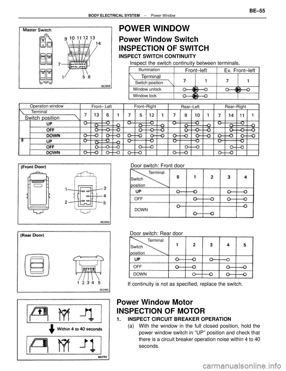
POWER WINDOW
Power Window Switch
INSPECTION OF SWITCH
INSPECT SWITCH CONTINUITY
Inspect the switch continuity between terminals.
If continuity is not as specified, replace the switch.Door switch: Front door
Door switch: Rear door
Operation windowSwitch position
Switch position
Window unlock
Switch
position
Switch
positionWindow lock
Ex. Front┬▒left
Front┬▒RightIllumination
Rear┬▒Right
Front┬▒left
Terminal
Front┬▒ Left
Terminal Terminal
TerminalRear┬▒Left
DOWN
DOWN OFFOFF
┬▒ BODY ELECTRICAL SYSTEMPower WindowBE┬▒55
Page 802 of 2389
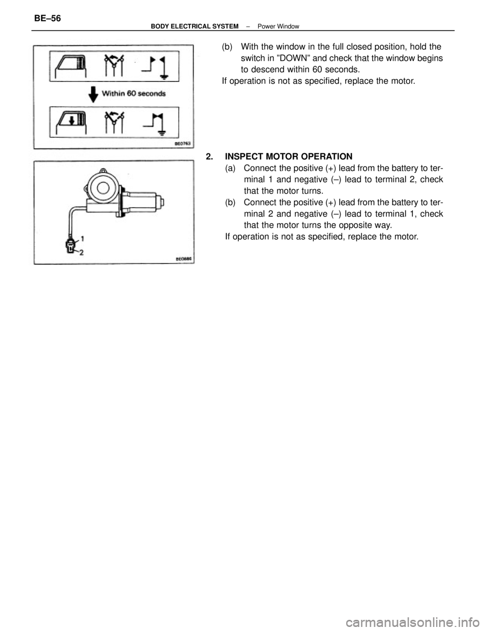
2. INSPECT MOTOR OPERATION
(a) Connect the positive (+) lead from the battery to ter-
minal 1 and negative (┬▒) lead to terminal 2, check
that the motor turns.
(b) Connect the positive (+) lead from the battery to ter-
minal 2 and negative (┬▒) lead to terminal 1, check
that the motor turns the opposite way.
If operation is not as specified, replace the motor. (b) With the window in the full closed position, hold the
switch in ┬║DOWN┬║ and check that the window begins
to descend within 60 seconds.
If operation is not as specified, replace the motor.
┬▒ BODY ELECTRICAL SYSTEMPower WindowBE┬▒56
Page 803 of 2389
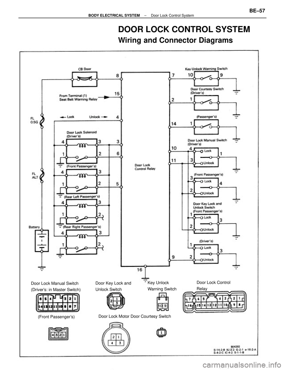
DOOR LOCK CONTROL SYSTEM
Wiring and Connector Diagrams
Door Lock Manual Switch
(Driver's: in Master Switch)
Door Lock Motor Door Courtesy SwitchDoor Lock Control
Relay Door Key Lock and
Unlock SwitchKey Unlock
Warning Switch
(Front Passenger's)
┬▒ BODY ELECTRICAL SYSTEMDoor Lock Control SystemBE┬▒57
Page 804 of 2389
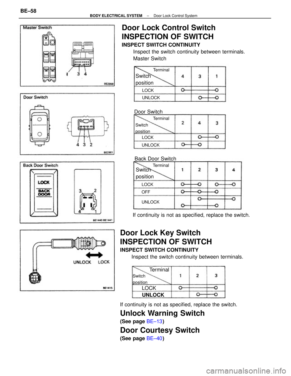
If continuity is not as specified, replace the switch.
Unlock Warning Switch
(See page BE┬▒13)
Door Courtesy Switch
(See page BE┬▒40)
Door Lock Control Switch
INSPECTION OF SWITCH
INSPECT SWITCH CONTINUITY
Inspect the switch continuity between terminals.
Master Switch
Door Lock Key Switch
INSPECTION OF SWITCH
INSPECT SWITCH CONTINUITY
Inspect the switch continuity between terminals.If continuity is not as specified, replace the switch.Back Door Switch
Switch
position
Door SwitchSwitch
position
Switch
position
Switch
position
Terminal
UNLOCK
TerminalTerminalTerminal
UNLOCKUNLOCKUNLOCK
LOCK
LOCKLOCK
LOCK
OFF
┬▒ BODY ELECTRICAL SYSTEMDoor Lock Control SystemBE┬▒58
Page 805 of 2389
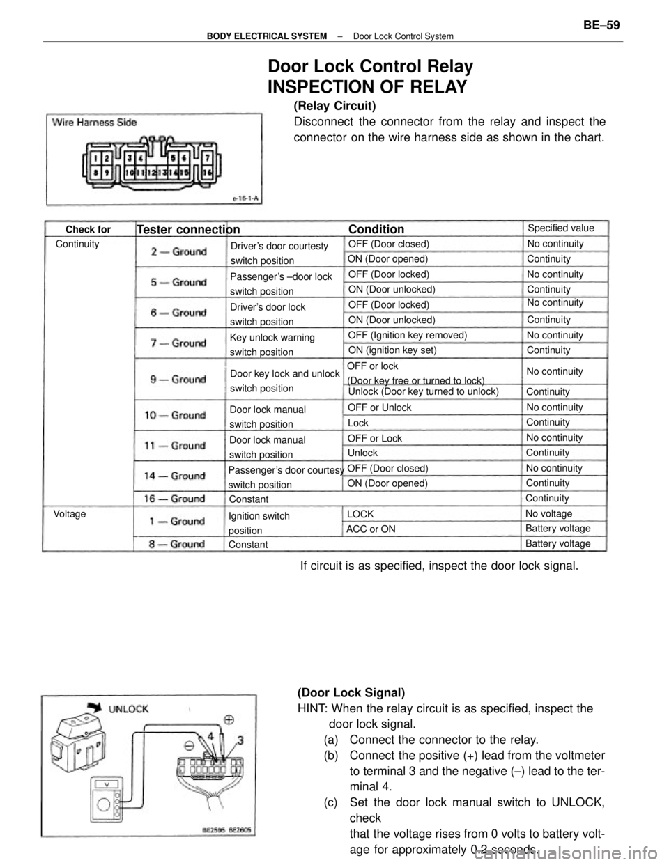
(Door Lock Signal)
HINT: When the relay circuit is as specified, inspect the
door lock signal.
(a) Connect the connector to the relay.
(b) Connect the positive (+) lead from the voltmeter
to terminal 3 and the negative (┬▒) lead to the ter-
minal 4.
(c) Set the door lock manual switch to UNLOCK,
check
that the voltage rises from 0 volts to battery volt-
age for approximately 0.2 seconds.
Door Lock Control Relay
INSPECTION OF RELAY
(Relay Circuit)
Disconnect the connector from the relay and inspect the
connector on the wire harness side as shown in the chart.
If circuit is as specified, inspect the door lock signal.
OFF or lock
(Door key free or turned to lock)
Passenger's door courtesy
switch positionPassenger's ┬▒door lock
switch positionDriver's door courtesty
switch position
Unlock (Door key turned to unlock) Door key lock and unlock
switch position Key unlock warning
switch positionOFF (Ignition key removed)
Door lock manual
switch position
Door lock manual
switch positionDriver's door lock
switch position
Ignition switch
positionON (ignition key set) ON (Door unlocked)
ON (Door unlocked) ON (Door opened)
Tester connection
OFF (Door locked)
ON (Door opened)OFF (Door locked)
OFF (Door closed)OFF (Door closed)Specified value
No continuity
Battery voltage Battery voltage OFF or UnlockNo continuity
No continuityNo continuity
No continuity
No continuity
No continuityNo continuity
Continuity OFF or Lock
No voltageContinuityContinuity
Continuity ContinuityContinuity
ContinuityContinuityContinuity
ACC or ON Continuity
ConditionCheck for
ConstantConstant
VoltageUnlock
LOCKLock
┬▒ BODY ELECTRICAL SYSTEMDoor Lock Control SystemBE┬▒59
Page 806 of 2389
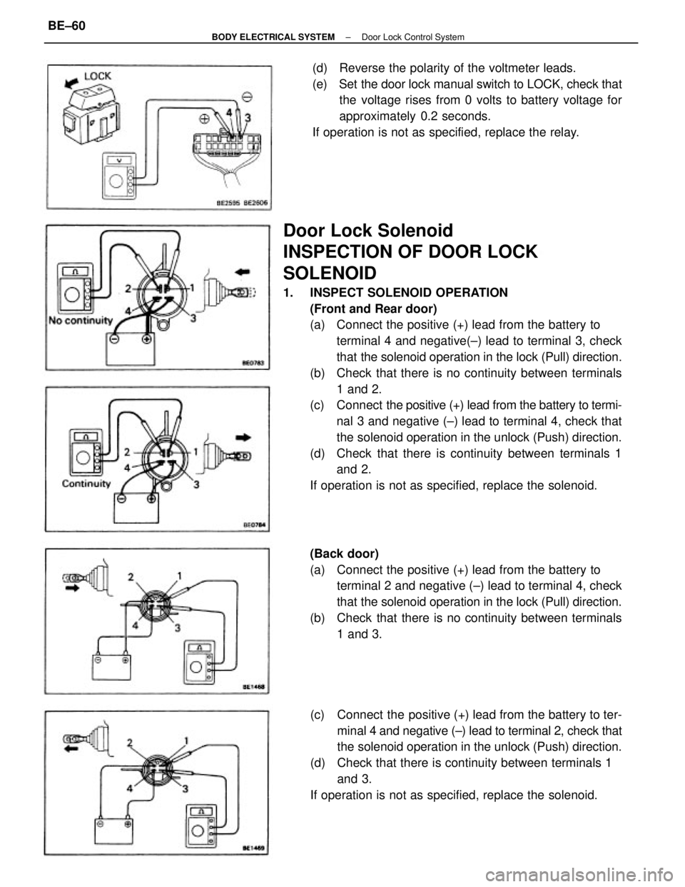
Door Lock Solenoid
INSPECTION OF DOOR LOCK
SOLENOID
1. INSPECT SOLENOID OPERATION
(Front and Rear door)
(a) Connect the positive (+) lead from the battery to
terminal 4 and negative(┬▒) lead to terminal 3, check
that the solenoid operation in the lock (Pull) direction.
(b) Check that there is no continuity between terminals
1 and 2.
(c) Connect the positive (+) lead from the battery to termi-
nal 3 and negative (┬▒) lead to terminal 4, check that
the solenoid operation in the unlock (Push) direction.
(d) Check that there is continuity between terminals 1
and 2.
If operation is not as specified, replace the solenoid.
(c) Connect the positive (+) lead from the battery to ter-
minal 4 and negative (┬▒) lead to terminal 2, check that
the solenoid operation in the unlock (Push) direction.
(d) Check that there is continuity between terminals 1
and 3.
If operation is not as specified, replace the solenoid. (Back door)
(a) Connect the positive (+) lead from the battery to
terminal 2 and negative (┬▒) lead to terminal 4, check
that the solenoid operation in the lock (Pull) direction.
(b) Check that there is no continuity between terminals
1 and 3. (d) Reverse the polarity of the voltmeter leads.
(e) Set the door lock manual switch to LOCK, check that
the voltage rises from 0 volts to battery voltage for
approximately 0.2 seconds.
If operation is not as specified, replace the relay.
┬▒ BODY ELECTRICAL SYSTEMDoor Lock Control SystemBE┬▒60
Page 807 of 2389
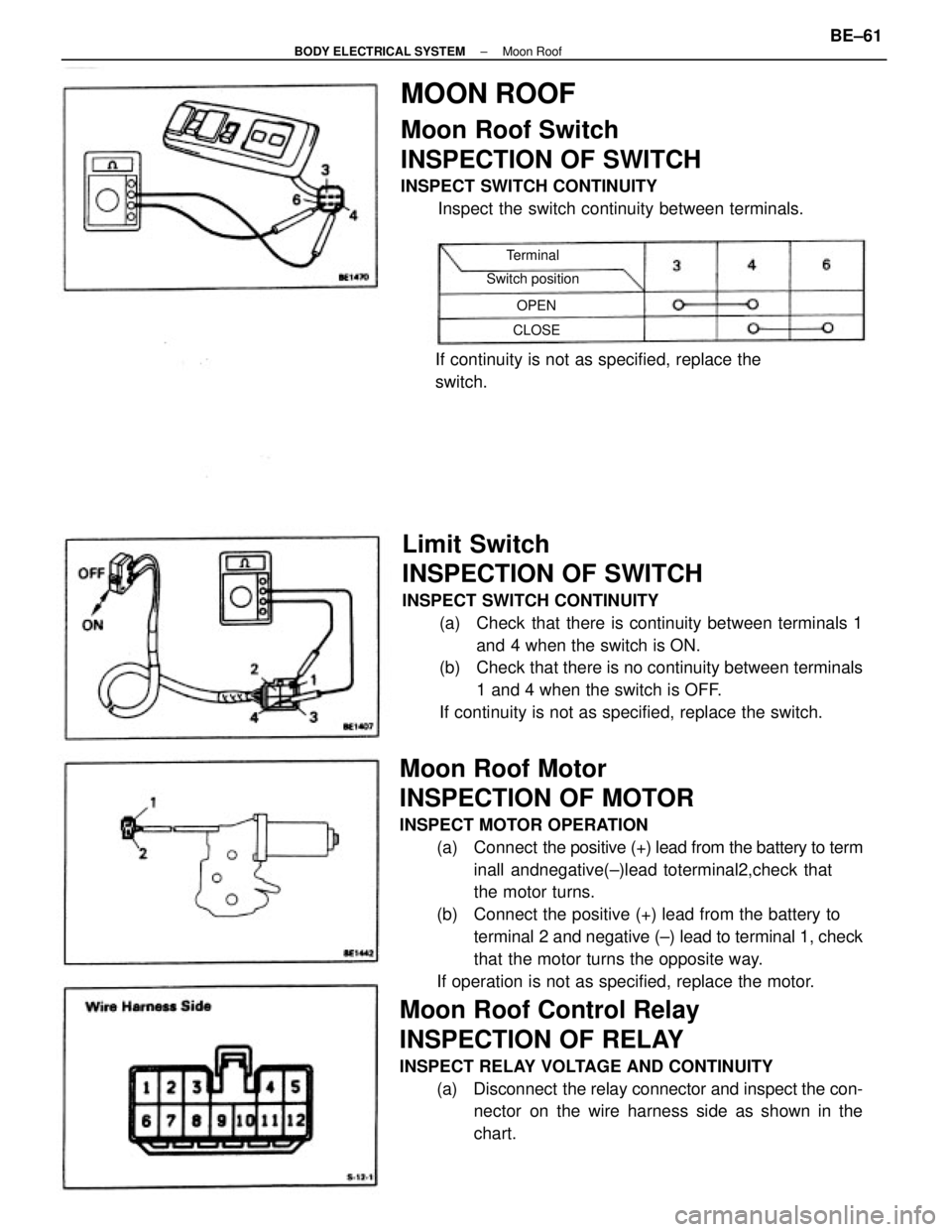
Moon Roof Motor
INSPECTION OF MOTOR
INSPECT MOTOR OPERATION
(a) Connect the positive (+) lead from the battery to term
inall andnegative(┬▒)lead toterminal2,check that
the motor turns.
(b) Connect the positive (+) lead from the battery to
terminal 2 and negative (┬▒) lead to terminal 1, check
that the motor turns the opposite way.
If operation is not as specified, replace the motor.
Moon Roof Control Relay
INSPECTION OF RELAY
INSPECT RELAY VOLTAGE AND CONTINUITY
(a) Disconnect the relay connector and inspect the con-
nector on the wire harness side as shown in the
chart.
Limit Switch
INSPECTION OF SWITCH
INSPECT SWITCH CONTINUITY
(a) Check that there is continuity between terminals 1
and 4 when the switch is ON.
(b) Check that there is no continuity between terminals
1 and 4 when the switch is OFF.
If continuity is not as specified, replace the switch.
MOON ROOF
Moon Roof Switch
INSPECTION OF SWITCH
INSPECT SWITCH CONTINUITY
Inspect the switch continuity between terminals.
If continuity is not as specified, replace the
switch.
Switch positionTerminal
CLOSEOPEN
┬▒ BODY ELECTRICAL SYSTEMMoon RoofBE┬▒61
Page 808 of 2389
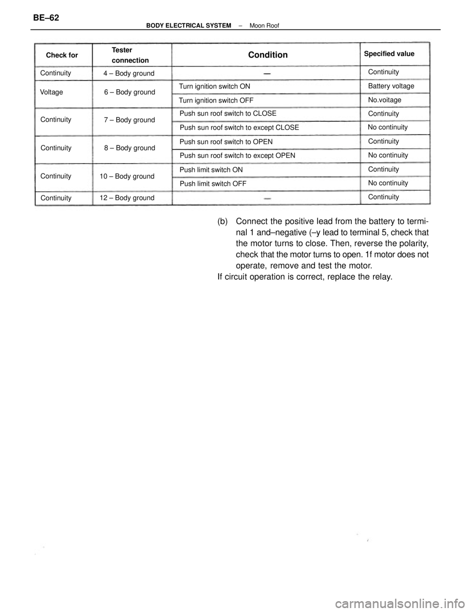
(b) Connect the positive lead from the battery to termi-
nal 1 and┬▒negative (┬▒y lead to terminal 5, check that
the motor turns to close. Then, reverse the polarity,
check that the motor turns to open. 1f motor does not
operate, remove and test the motor.
If circuit operation is correct, replace the relay.
Push sun roof switch to except CLOSE
Push sun roof switch to except OPEN Push sun roof switch to CLOSE
Push sun roof switch to OPEN Turn ignition switch OFFTurn ignition switch ON
Push limit switch ON
Push limit switch OFFSpecified value Tester
connection
10 ┬▒ Body ground
12 ┬▒ Body ground8 ┬▒ Body ground 4 ┬▒ Body ground
6 ┬▒ Body ground
7 ┬▒ Body groundBattery voltage
No continuity
No continuity No continuity
Continuity Continuity
Continuity
Continuity Continuity
Continuity No.voitage
Continuity Continuity
Continuity Continuity
ConditionCheck for
Voltage
┬▒ BODY ELECTRICAL SYSTEMMoon RoofBE┬▒62
Page 809 of 2389
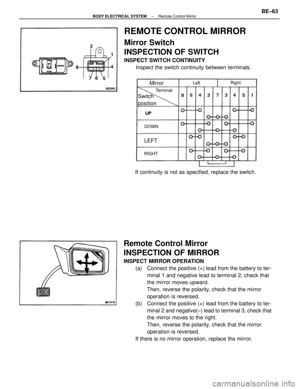
Remote Control Mirror
INSPECTION OF MIRROR
INSPECT MIRROR OPERATION
(a) Connect the positive (+) lead from the battery to ter-
minal 1 and negative lead to terminal 2, check that
the mirror moves upward.
Then, reverse the polarity, check that the mirror
operation is reversed.
(b) Connect the positive (+) lead from the battery to ter-
minal 2 and negative(┬▒) lead to terminal 3, check that
the mirror moves to the right.
Then, reverse the polarity, check that the mirror
operation is reversed.
If there is no mirror operation, replace the mirror.
REMOTE CONTROL MIRROR
Mirror Switch
INSPECTION OF SWITCH
INSPECT SWITCH CONTINUITY
Inspect the switch continuity between terminals.
If continuity is not as specified, replace the switch.Switch
position
Terminal
Mirror
RIGHTRight
DOWN
LEFT
Left
┬▒ BODY ELECTRICAL SYSTEMRemote Control MirrorBE┬▒63
Page 810 of 2389
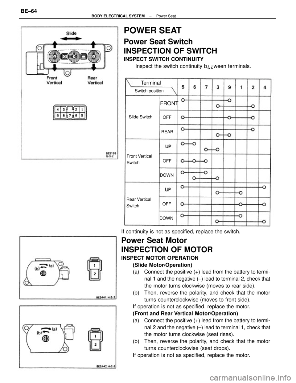
If continuity is not as specified, replace the switch.
Power Seat Motor
INSPECTION OF MOTOR
INSPECT MOTOR OPERATION
(Slide Motor/Operation)
(a) Connect the positive (+) lead from the battery to termi-
nal 1 and the negative (┬▒) lead to terminal 2, check that
the motor turns clockwise (moves to rear side).
(b) Then, reverse the polarity, and check that the motor
turns counterclockwise (moves to front side).
If operation is not as specified, replace the motor.
(Front and Rear Vertical Motor/Operation)
(a) Connect the positive (+) lead from the battery to termi-
nal 2 and the negative (┬▒) lead to terminal 1, check that
the motor turns clockwise (seat rises).
(b) Then, reverse the polarity, and check that the motor
turns counterclockwise (seat drops).
If operation is not as specified, replace the motor.
POWER SEAT
Power Seat Switch
INSPECTION OF SWITCH
INSPECT SWITCH CONTINUITY
Inspect the switch continuity b┬┐┬┐ween terminals.
Front Vertical
Switch
Rear Vertical
SwitchSwitch position
Slide Switch
Terminal
FRONT
DOWNDOWNREAROFF
OFFOFF
┬▒ BODY ELECTRICAL SYSTEMPower SeatBE┬▒64