TOYOTA CAMRY V20 1986 Service Information
Manufacturer: TOYOTA, Model Year: 1986, Model line: CAMRY V20, Model: TOYOTA CAMRY V20 1986Pages: 2389, PDF Size: 84.44 MB
Page 821 of 2389
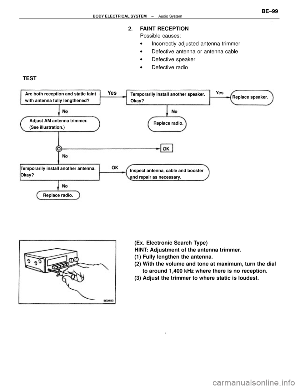
(Ex. Electronic Search Type)
HINT: Adjustment of the antenna trimmer.
(1) Fully lengthen the antenna.
(2) With the volume and tone at maximum, turn the dial
to around 1,400 kHz where there is no reception.
(3) Adjust the trimmer to where static is loudest. 2. FAINT RECEPTION
Possible causes:
wIncorrectly adjusted antenna trimmer
wDefective antenna or antenna cable
wDefective speaker
wDefective radio
Temporarily install another speaker.
Okay?
Temporarily install another antenna.
Okay?Inspect antenna, cable and booster
and repair as necessary. Are both reception and static faint
with antenna fully lengthened?
Adjust AM antenna trimmer.
(See illustration.)Replace speaker.
Replace radio.
Replace radio.
TEST
Ye sYe s
± BODY ELECTRICAL SYSTEMAudio SystemBE±99
Page 822 of 2389
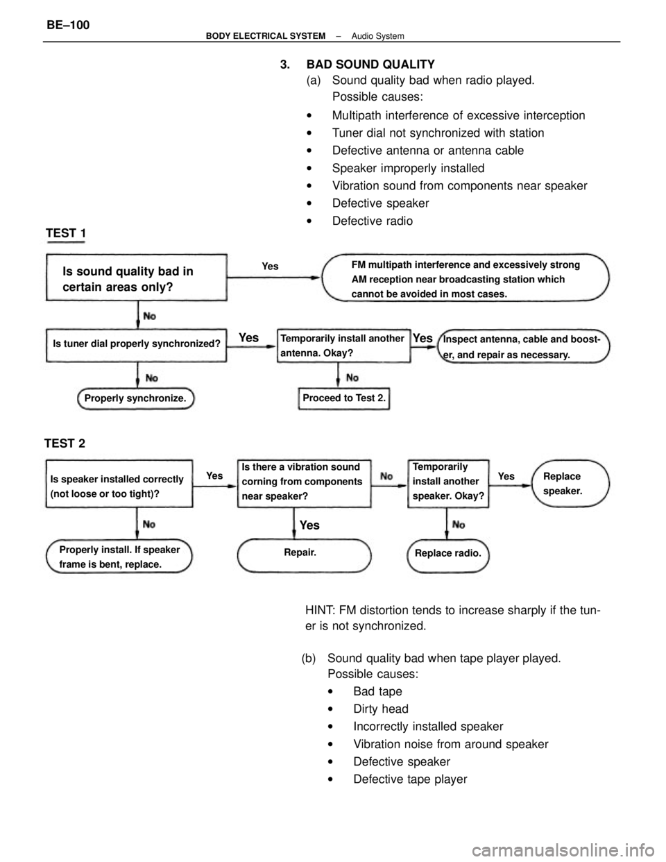
3. BAD SOUND QUALITY
(a) Sound quality bad when radio played.
Possible causes:
wMuItipath interference of excessive interception
wTuner dial not synchronized with station
wDefective antenna or antenna cable
wSpeaker improperly installed
wVibration sound from components near speaker
wDefective speaker
wDefective radio
(b) Sound quality bad when tape player played.
Possible causes:
wBad tape
wDirty head
wIncorrectly installed speaker
wVibration noise from around speaker
wDefective speaker
wDefective tape player HINT: FM distortion tends to increase sharply if the tun-
er is not synchronized.
FM multipath interference and excessively strong
AM reception near broadcasting station which
cannot be avoided in most cases.
Is there a vibration sound
corning from components
near speaker?Inspect antenna, cable and boost-
er, and repair as necessary.Is sound quality bad in
certain areas only?
Is speaker installed correctly
(not loose or too tight)?Temporarily install another
antenna. Okay?
Properly install. If speaker
frame is bent, replace. Is tuner dial properly synchronized?
Temporarily
install another
speaker. Okay? Properly synchronize.Proceed to Test 2.
Replace radio.Replace
speaker.
TEST 2TEST 1
Repair.
Ye s
Ye s
Ye s
Ye s
Ye s
Ye s
± BODY ELECTRICAL SYSTEMAudio SystemBE±100
Page 823 of 2389
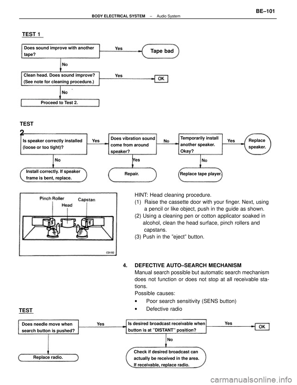
HINT: Head cleaning procedure.
(1) Raise the cassette door with your finger. Next, using
a pencil or like object, push in the guide as shown.
(2) Using a cleaning pen or cotton applicator soaked in
alcohol, clean the head surface, pinch rollers and
capstans.
(3) Push in the ºejectº button.
4. DEFECTIVE AUTO±SEARCH MECHANISM
Manual search possible but automatic search mechanism
does not function or does not stop at all receivable sta-
tions.
Possible causes:
wPoor search sensitivity (SENS button)
wDefective radio
Check if desired broadcast can
actually be received in the area.
If receivable, replace radio. Is desired broadcast receivable when
button is at ºDISTANTº position? Clean head. Does sound improve?
(See note for cleaning procedure.)Does sound improve with another
tape?
Is speaker correctly installed
(loose or too tight)?Does vibration sound
come from around
speaker?
Install correctly. If speaker
frame is bent, replace.Temporarily install
another speaker.
Okay?
Does needle move when
search button is pushed?Replace tape player. Proceed to Test 2.
Replace radio.Replace
speaker.
TEST
2
Tape bad TEST 1
Repair.
TEST
Ye s Ye s
Ye s Ye s
Ye s
Ye s
Ye s
± BODY ELECTRICAL SYSTEMAudio SystemBE±101
Page 824 of 2389
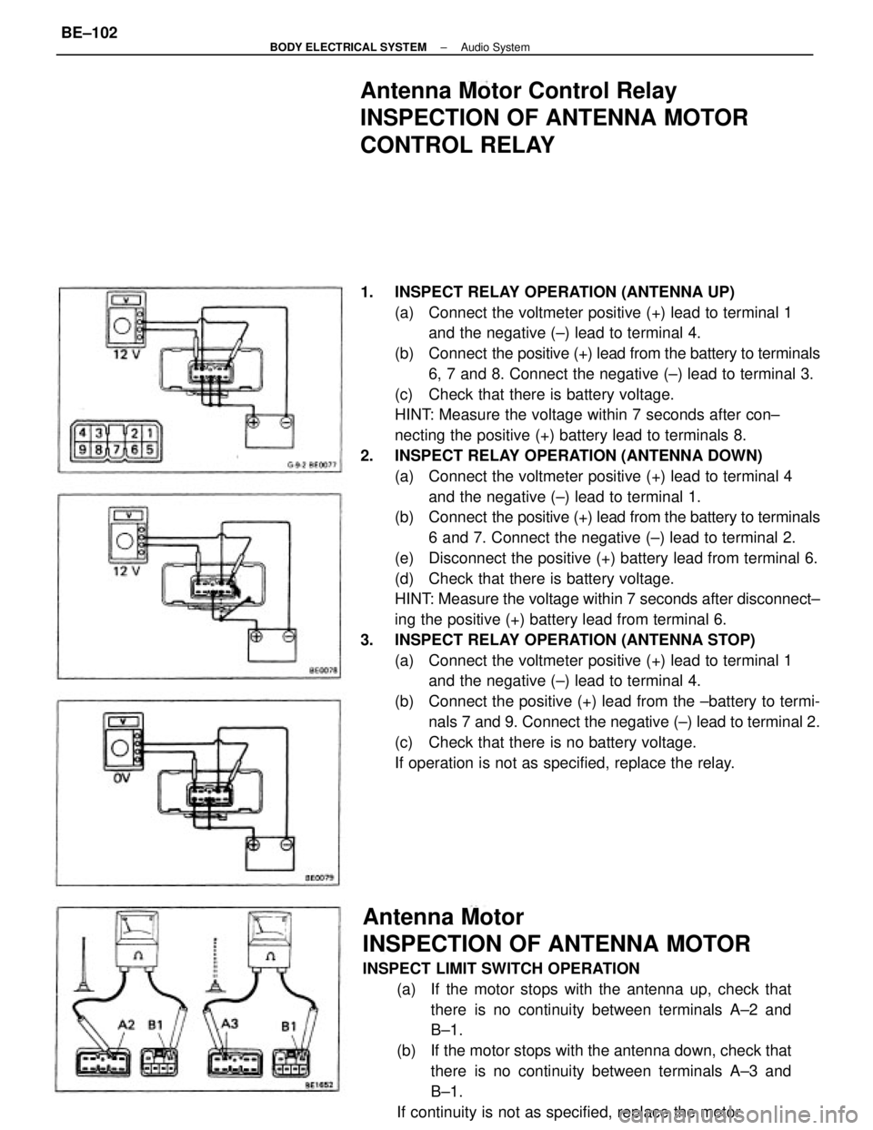
1. INSPECT RELAY OPERATION (ANTENNA UP)
(a) Connect the voltmeter positive (+) lead to terminal 1
and the negative (±) lead to terminal 4.
(b) Connect the positive (+) lead from the battery to terminals
6, 7 and 8. Connect the negative (±) lead to terminal 3.
(c) Check that there is battery voltage.
HINT: Measure the voltage within 7 seconds after con±
necting the positive (+) battery lead to terminals 8.
2. INSPECT RELAY OPERATION (ANTENNA DOWN)
(a) Connect the voltmeter positive (+) lead to terminal 4
and the negative (±) lead to terminal 1.
(b) Connect the positive (+) lead from the battery to terminals
6 and 7. Connect the negative (±) lead to terminal 2.
(e) Disconnect the positive (+) battery lead from terminal 6.
(d) Check that there is battery voltage.
HINT: Measure the voltage within 7 seconds after disconnect±
ing the positive (+) battery lead from terminal 6.
3. INSPECT RELAY OPERATION (ANTENNA STOP)
(a) Connect the voltmeter positive (+) lead to terminal 1
and the negative (±) lead to terminal 4.
(b) Connect the positive (+) lead from the ±battery to termi-
nals 7 and 9. Connect the negative (±) lead to terminal 2.
(c) Check that there is no battery voltage.
If operation is not as specified, replace the relay.
Antenna Motor
INSPECTION OF ANTENNA MOTOR
INSPECT LIMIT SWITCH OPERATION
(a) If the motor stops with the antenna up, check that
there is no continuity between terminals A±2 and
B±1.
(b) If the motor stops with the antenna down, check that
there is no continuity between terminals A±3 and
B±1.
If continuity is not as specified, replace the motor.
Antenna Motor Control Relay
INSPECTION OF ANTENNA MOTOR
CONTROL RELAY
± BODY ELECTRICAL SYSTEMAudio SystemBE±102
Page 825 of 2389
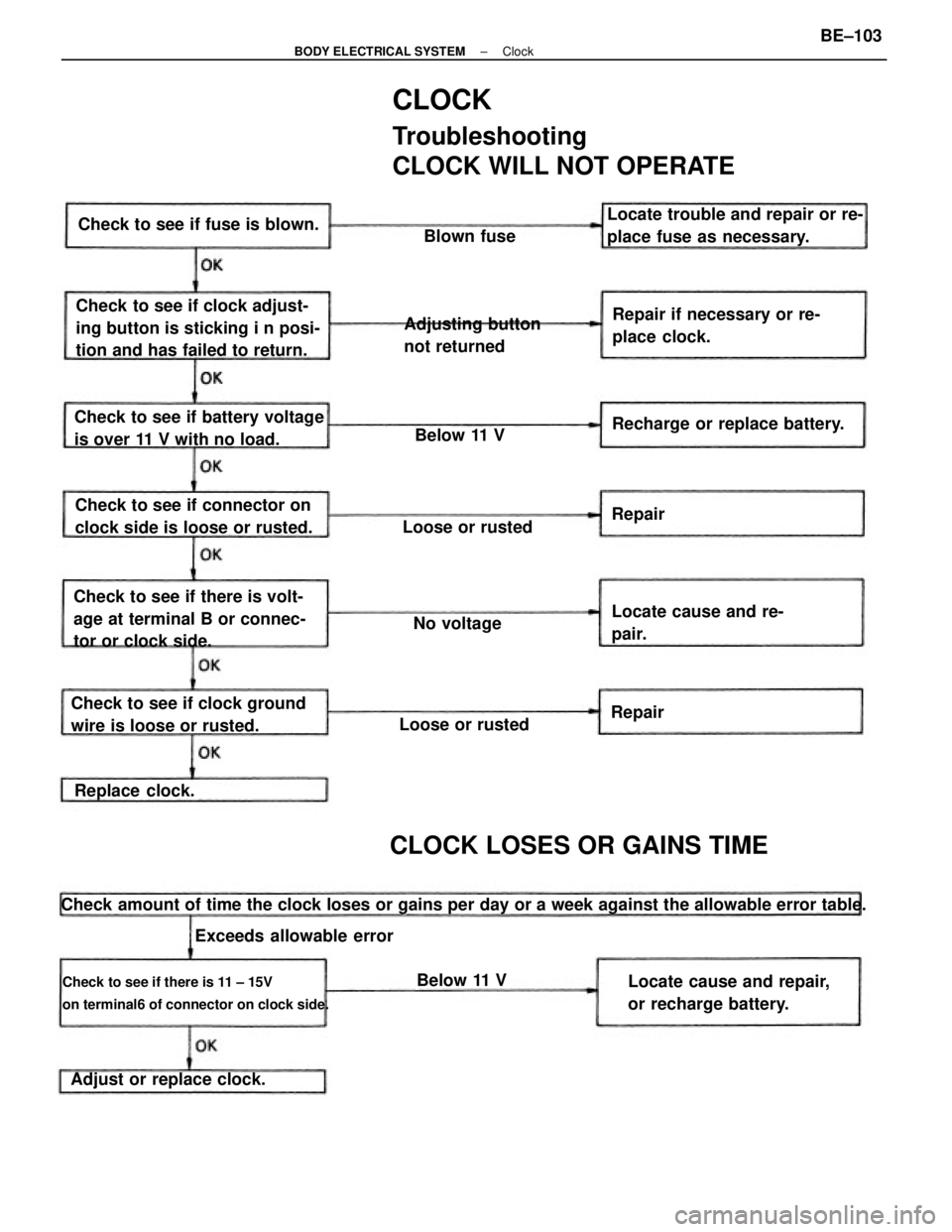
CLOCK
Troubleshooting
CLOCK WILL NOT OPERATE
Check amount of time the clock loses or gains per day or a week against the allowable error table.
Check to see if there is 11 ± 15V
on terminal6 of connector on clock side.
Check to see if clock adjust-
ing button is sticking i n posi-
tion and has failed to return.
Check to see if there is volt-
age at terminal B or connec-
tor or clock side.
Check to see if clock ground
wire is loose or rusted.Check to see if battery voltage
is over 11 V with no load.Repair if necessary or re-
place clock. Locate trouble and repair or re-
place fuse as necessary.
Locate cause and repair,
or recharge battery. Check to see if connector on
clock side is loose or rusted.
CLOCK LOSES OR GAINS TIME
Adjusting button
not returned Check to see if fuse is blown.
Recharge or replace battery.
Adjust or replace clock.Locate cause and re-
pair.
Exceeds allowable errorLoose or rustedLoose or rusted
Replace clock.No voltageBlown fuse
Below 11 V
Below 11 VRepair
Repair
± BODY ELECTRICAL SYSTEMClockBE±103
Page 826 of 2389
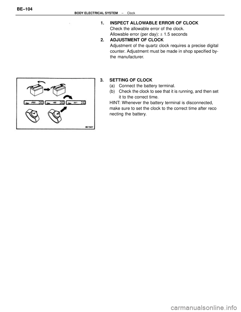
1. INSPECT ALLOWABLE ERROR OF CLOCK
Check the allowable error of the clock.
Allowable error (per day):
+ 1.5 seconds
2. ADJUSTMENT OF CLOCK
Adjustment of the quartz clock requires a precise digital
counter. Adjustment must be made in shop specified by-
the manufacturer.
3. SETTING OF CLOCK
(a) Connect the battery terminal.
(b) Check the clock to see that it is running, and then set
it to the correct time.
HINT: Whenever the battery terminal is disconnected,
make sure to set the clock to the correct time after reco
necting the battery.
± BODY ELECTRICAL SYSTEMClockBE±104
Page 827 of 2389
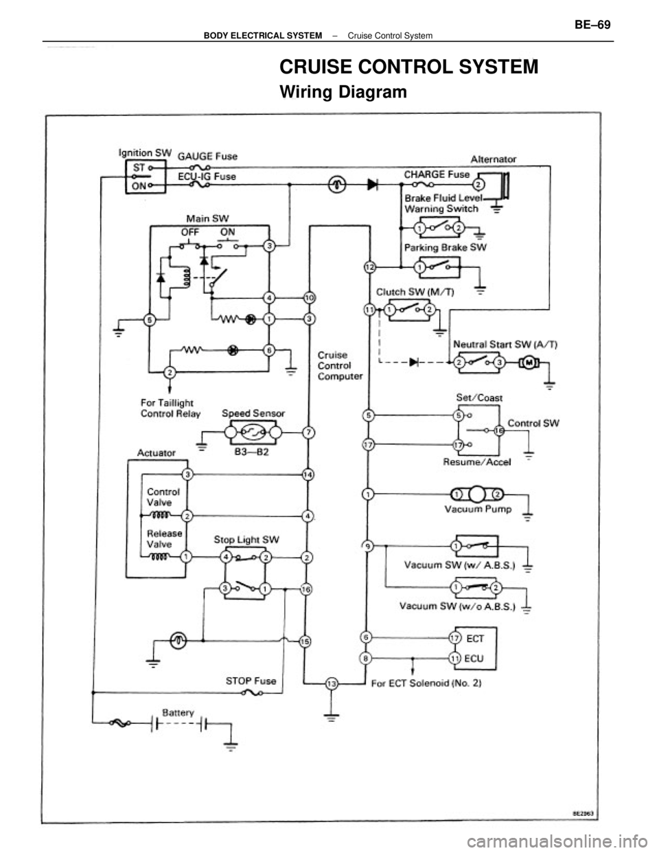
CRUISE CONTROL SYSTEM
Wiring Diagram
± BODY ELECTRICAL SYSTEMCruise Control SystemBE±69
Page 828 of 2389
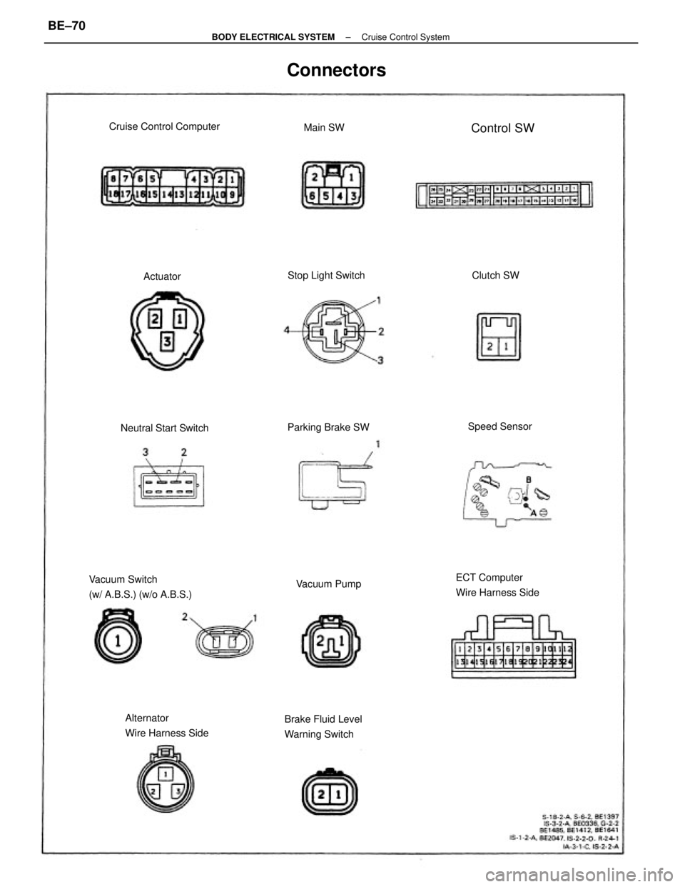
Vacuum Switch
(w/ A.B.S.) (w/o A.B.S.)ECT Computer
Wire Harness Side
Alternator
Wire Harness SideBrake Fluid Level
Warning Switch
Connectors
Cruise Control Computer
Neutral Start SwitchStop Light Switch
Parking Brake SW
Vacuum PumpSpeed SensorControl SW
Clutch SW Main SW
Actuator
± BODY ELECTRICAL SYSTEMCruise Control SystemBE±70
Page 829 of 2389
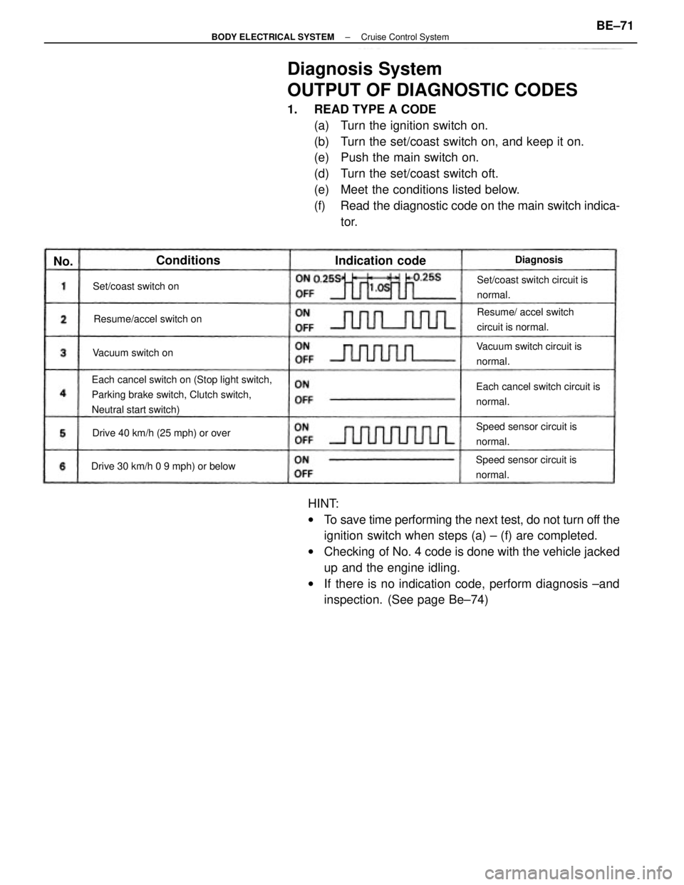
Diagnosis System
OUTPUT OF DIAGNOSTIC CODES
1. READ TYPE A CODE
(a) Turn the ignition switch on.
(b) Turn the set/coast switch on, and keep it on.
(e) Push the main switch on.
(d) Turn the set/coast switch oft.
(e) Meet the conditions listed below.
(f) Read the diagnostic code on the main switch indica-
tor.
HINT:
wTo save time performing the next test, do not turn off the
ignition switch when steps (a) ± (f) are completed.
wChecking of No. 4 code is done with the vehicle jacked
up and the engine idling.
wIf there is no indication code, perform diagnosis ±and
inspection. (See page Be±74)
Each cancel switch on (Stop light switch,
Parking brake switch, Clutch switch,
Neutral start switch)Each cancel switch circuit is
normal.Set/coast switch circuit is
normal.
Vacuum switch circuit is
normal.Resume/ accel switch
circuit is normal.
Speed sensor circuit is
normal.Speed sensor circuit is
normal.
Drive 30 km/h 0 9 mph) or belowDrive 40 km/h (25 mph) or overResume/accel switch on Set/coast switch on
Vacuum switch on
Indication code ConditionsDiagnosisNo.
± BODY ELECTRICAL SYSTEMCruise Control SystemBE±71
Page 830 of 2389
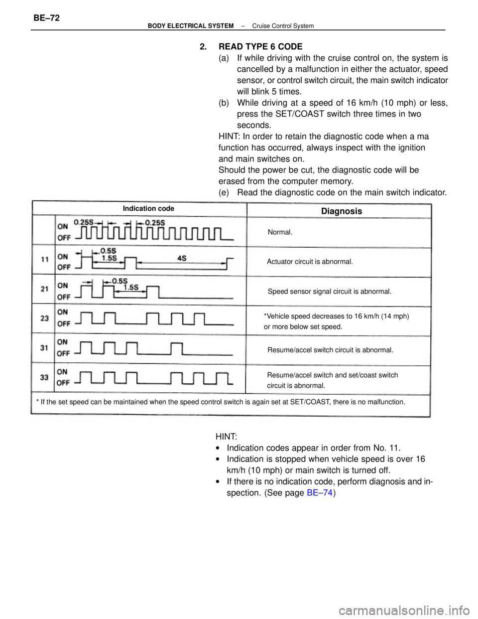
2. READ TYPE 6 CODE
(a) If while driving with the cruise control on, the system is
cancelled by a malfunction in either the actuator, speed
sensor, or control switch circuit, the main switch indicator
will blink 5 times.
(b) While driving at a speed of 16 km/h (10 mph) or less,
press the SET/COAST switch three times in two
seconds.
HINT: In order to retain the diagnostic code when a ma
function has occurred, always inspect with the ignition
and main switches on.
Should the power be cut, the diagnostic code will be
erased from the computer memory.
(e) Read the diagnostic code on the main switch indicator.
HINT:
wIndication codes appear in order from No. 11.
wIndication is stopped when vehicle speed is over 16
km/h (10 mph) or main switch is turned off.
wIf there is no indication code, perform diagnosis and in-
spection. (See page BE±74)
* If the set speed can be maintained when the speed control switch is again set at SET/COAST, there is no malfunction.*Vehicle speed decreases to 16 km/h (14 mph)
or more below set speed.
Resume/accel switch and set/coast switch
circuit is abnormal.Resume/accel switch circuit is abnormal.Speed sensor signal circuit is abnormal. Actuator circuit is abnormal. Indication code
Diagnosis
Normal.
± BODY ELECTRICAL SYSTEMCruise Control SystemBE±72