TOYOTA RAV4 1996 Service Repair Manual
Manufacturer: TOYOTA, Model Year: 1996, Model line: RAV4, Model: TOYOTA RAV4 1996Pages: 1632, PDF Size: 41.64 MB
Page 1411 of 1632
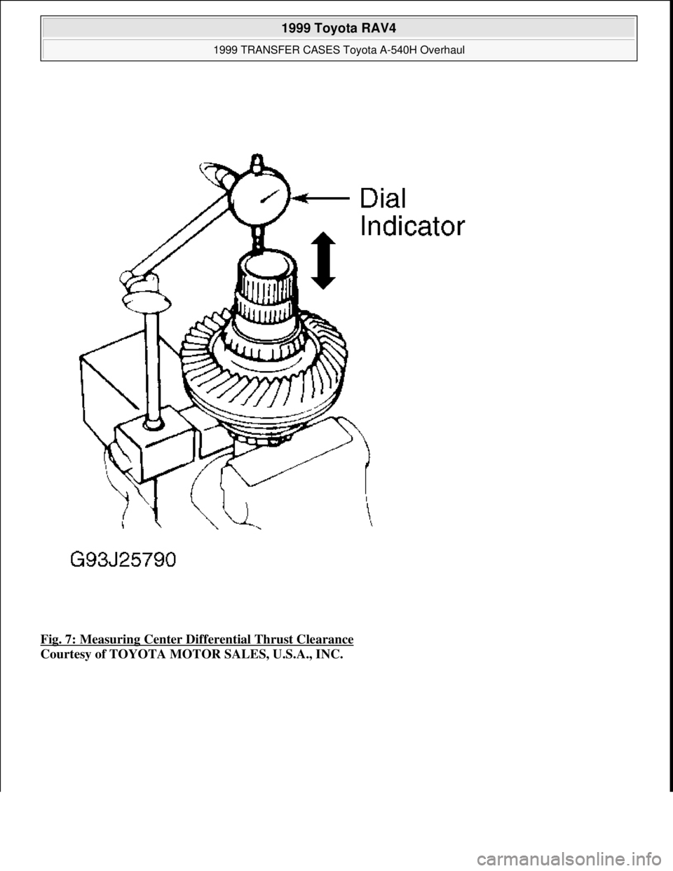
Fig. 7: Measuring Center Differential Thrust Clearance
Courtesy of TOYOTA MOTOR SALES, U.S.A., INC.
1999 Toyota RAV4
1999 TRANSFER CASES Toyota A-540H Overhaul
Microsoft
Sunday, November 22, 2009 10:49:16 AMPage 11 © 2005 Mitchell Repair Information Company, LLC.
Page 1412 of 1632
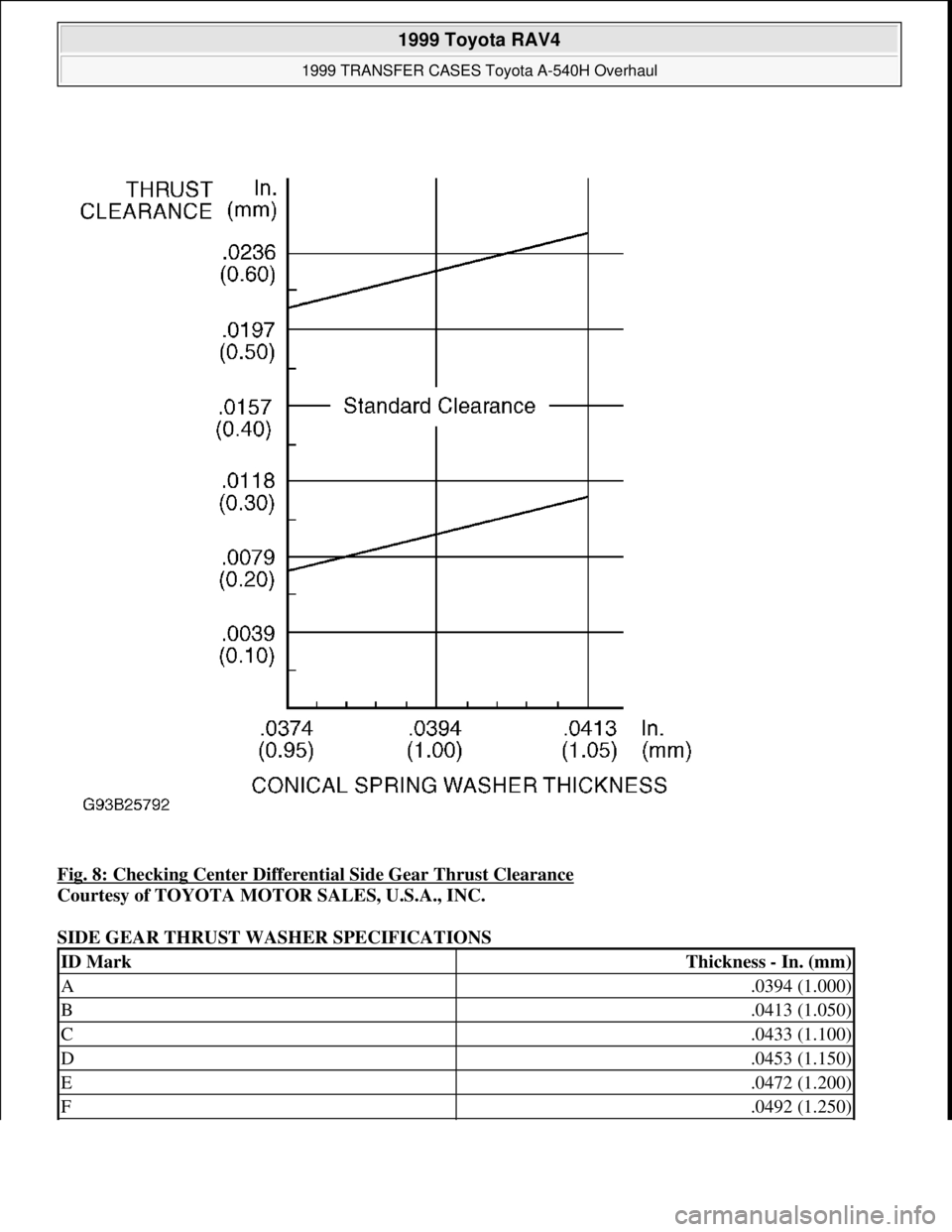
Fig. 8: Checking Center Differential Side Gear Thrust Clearance
Courtesy of TOYOTA MOTOR SALES, U.S.A., INC.
SIDE GEAR THRUST WASHER SPECIFICATIONS
ID MarkThickness - In. (mm)
A.0394 (1.000)
B.0413 (1.050)
C.0433 (1.100)
D.0453 (1.150)
E.0472 (1.200)
F.0492 (1.250)
1999 Toyota RAV4
1999 TRANSFER CASES Toyota A-540H Overhaul
Microsoft
Sunday, November 22, 2009 10:49:16 AMPage 12 © 2005 Mitchell Repair Information Company, LLC.
Page 1413 of 1632
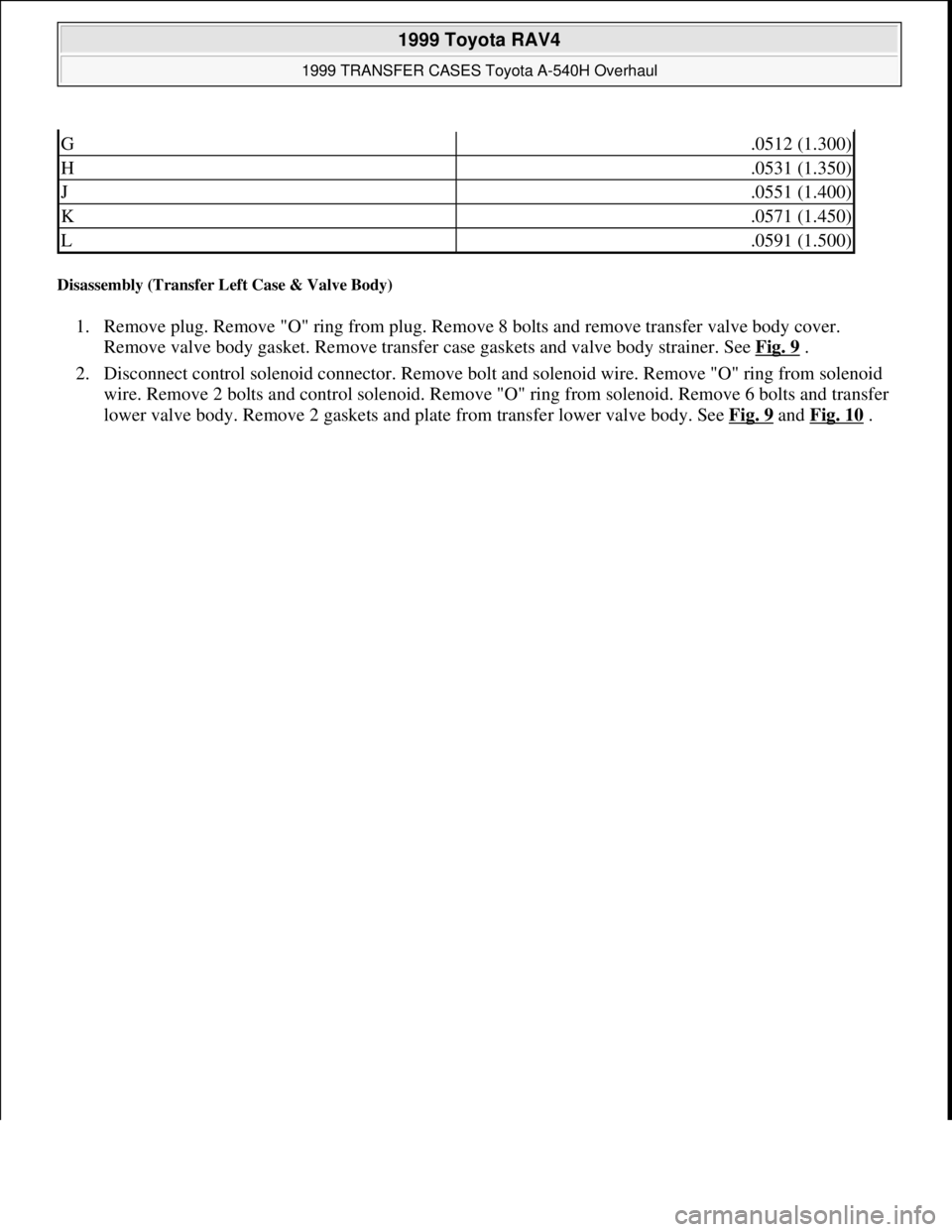
Disassembly (Transfer Left Case & Valve Body)
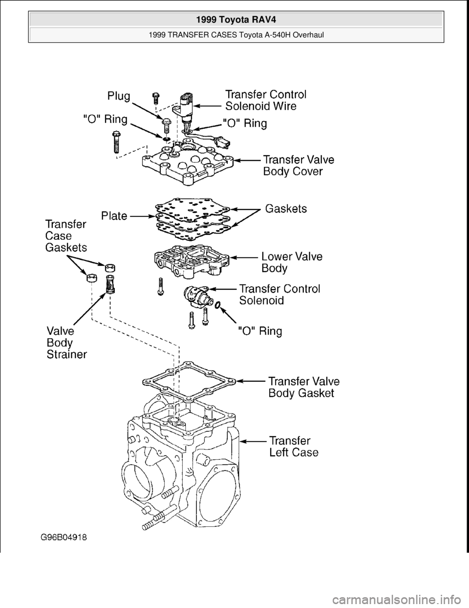
1. Remove plug. Remove "O" ring from plug. Remove 8 bolts and remove transfer valve body cover.
Remove valve body gasket. Remove transfer case gaskets and valve body strainer. See Fig. 9
.
2. Disconnect control solenoid connector. Remove bolt and solenoid wire. Remove "O" ring from solenoid
wire. Remove 2 bolts and control solenoid. Remove "O" ring from solenoid. Remove 6 bolts and transfer
lower valve bod
y. Remove 2 gaskets and plate from transfer lower valve body. See Fig. 9and Fig. 10.
G.0512 (1.300)
H.0531 (1.350)
J.0551 (1.400)
K.0571 (1.450)
L.0591 (1.500)
1999 Toyota RAV4
1999 TRANSFER CASES Toyota A-540H Overhaul
Microsoft
Sunday, November 22, 2009 10:49:16 AMPage 13 © 2005 Mitchell Repair Information Company, LLC.
Page 1414 of 1632
1999 Toyota RAV4
1999 TRANSFER CASES Toyota A-540H Overhaul
Microsoft
Sunday, November 22, 2009 10:49:16 AMPage 14 © 2005 Mitchell Repair Information Company, LLC.
Page 1415 of 1632
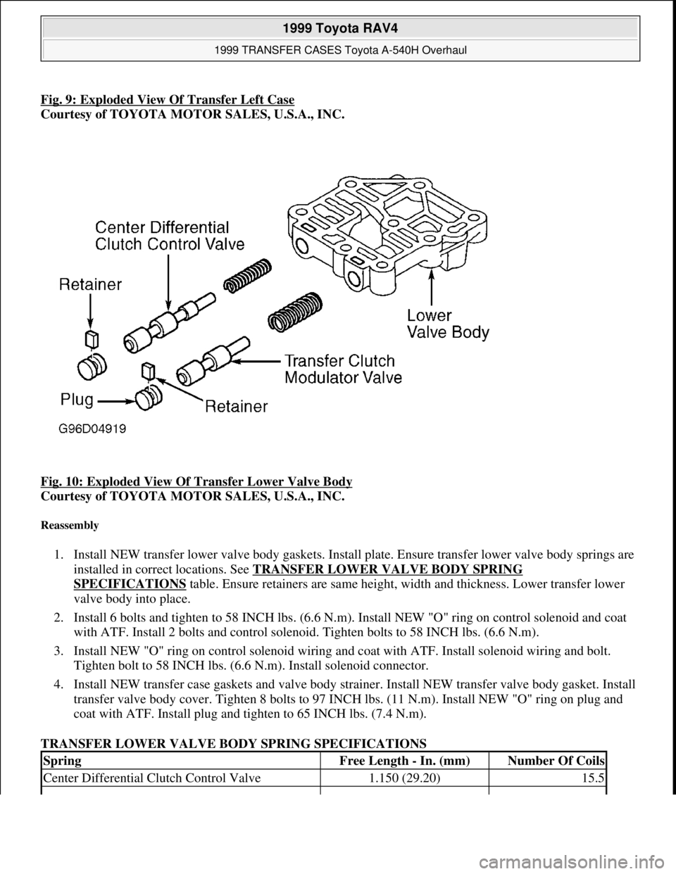
Fig. 9: Exploded View Of Transfer Left Case
Courtesy of TOYOTA MOTOR SALES, U.S.A., INC.
Fig. 10: Exploded View Of Transfer Lower Valve Body
Courtesy of TOYOTA MOTOR SALES, U.S.A., INC.
Reassembly
1. Install NEW transfer lower valve body gaskets. Install plate. Ensure transfer lower valve body springs are
installed in correct locations. See TRANSFER LOWER VALVE BODY SPRING
SPECIFICATIONS table. Ensure retainers are same height, width and thickness. Lower transfer lower
valve body into place.
2. Install 6 bolts and tighten to 58 INCH lbs. (6.6 N.m). Install NEW "O" ring on control solenoid and coat
with ATF. Install 2 bolts and control solenoid. Tighten bolts to 58 INCH lbs. (6.6 N.m).
3. Install NEW "O" ring on control solenoid wiring and coat with ATF. Install solenoid wiring and bolt.
Tighten bolt to 58 INCH lbs. (6.6 N.m). Install solenoid connector.
4. Install NEW transfer case gaskets and valve body strainer. Install NEW transfer valve body gasket. Install
transfer valve body cover. Tighten 8 bolts to 97 INCH lbs. (11 N.m). Install NEW "O" ring on plug and
coat with ATF. Install plug and tighten to 65 INCH lbs. (7.4 N.m).
TRANSFER LOWER VALVE BODY SPRING SPECIFICATIONS
SpringFree Length - In. (mm)Number Of Coils
Center Differential Clutch Control Valve1.150 (29.20)15.5
1999 Toyota RAV4
1999 TRANSFER CASES Toyota A-540H Overhaul
Microsoft
Sunday, November 22, 2009 10:49:16 AMPage 15 © 2005 Mitchell Repair Information Company, LLC.
Page 1416 of 1632
Reassembly (Transfer Case)
1. Install case side plate washer. Using press, install case side outer race. Using bearing replacer and an
arbor press, install right case side outer race. Install bearing adjusting nut and oil reservoir until nut and
reservoir touch outer race. See Fig. 2
.
2. Install shim(s) to driven pinion bearing cage assembly. Install same thickness shim(s) as removed. Install
driven pinion bearing cage. Tighten to 29 ft. lbs. (39 N.m). DO NOT install "O" ring. Install ring gear
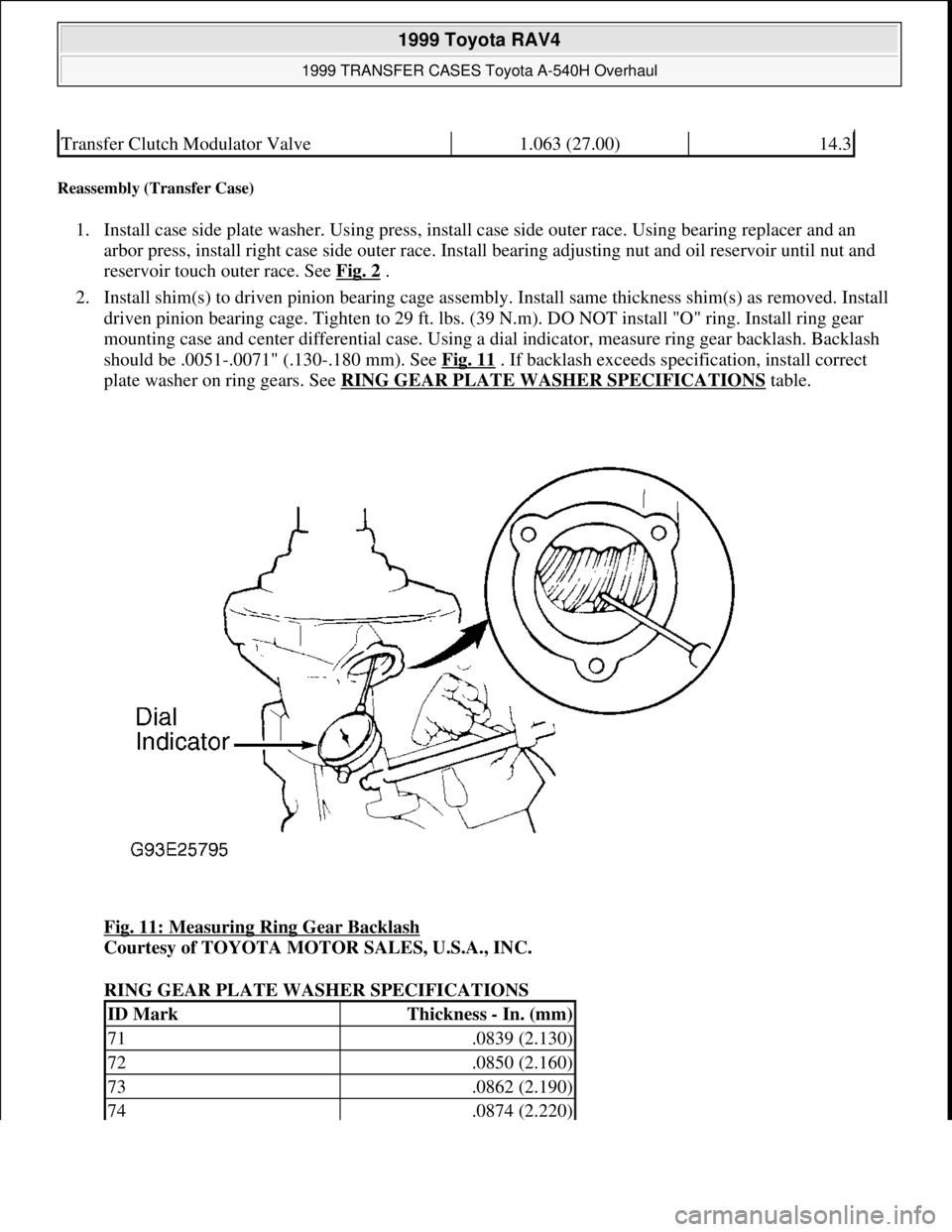
mounting case and center differential case. Using a dial indicator, measure ring gear backlash. Backlash
should be .0051-.0071" (.130-.180 mm). See Fig. 11
. If backlash exceeds specification, install correct
plate washer on ring gears. See RING GEAR PLATE WASHER SPECIFICATIONS
table.
Fig. 11: Measuring Ring Gear Backlash
Courtesy of TOYOTA MOTOR SALES, U.S.A., INC.
RING GEAR PLATE WASHER SPECIFICATIONS
Transfer Clutch Modulator Valve1.063 (27.00)14.3
ID MarkThickness - In. (mm)
71.0839 (2.130)
72.0850 (2.160)
73.0862 (2.190)
74.0874 (2.220)
1999 Toyota RAV4
1999 TRANSFER CASES Toyota A-540H Overhaul
Microsoft
Sunday, November 22, 2009 10:49:16 AMPage 16 © 2005 Mitchell Repair Information Company, LLC.
Page 1417 of 1632
3. Install right case. DO NOT apply seal packing and gasket. Tighten bolts to 32 ft. lbs. (44 N.m). Using
Lock Nut Wrench (09326-20011) and spring tension gauge, measure total preload. Total preload at
starting point with new bearing is 2.9-3.1 lbs. (1.3-1.4 kg). With used bearing, preload should be 1.1-2.0
lbs. (.5-.9 kg).
4. Add drive pinion preload to preload from previous step. Rotate drive pinion counterclockwise and
clockwise several times. Using Adjusting Nut Wrench (09318-12010), adjust total preload by tightening
bearing adjusting nut in small increments. Measure ring gear backlash. Backlash should be .0051-
.0071" (.130-180 mm). If backlash exceeds specification, install correct plate washer on ring gear. See
RING GEAR PLATE WASHER SPECIFICATIONS
table.
5. Check tooth contact. Coat 3 or 4 teeth at 4 different positions on ring gear with Red lead. Rotate ring
gear, and inspect teeth pattern. See Fig. 12
. If teeth are not meshing properly, install proper shim and
plate washer. See RING GEAR PLATE WASHER SPECIFICATIONS
and RING GEAR SHIM
SPECIFICATIONS tables.
75.0886 (2.250)
76.0898 (2.280)
77.0909 (2.310)
78.0921 (2.340)
79.0933 (2.370)
80.0945 (2.400)
81.0957 (2.430)
82.0969 (2.460)
83.0980 (2.490)
84.0992 (2.520)
85.1004 (2.550)
86.1016 (2.580)
87.1028 (2.610)
88.1039 (2.640)
89.1051 (2.670)
90.1063 (2.700)
91.1075 (2.730)
92.1087 (2.760)
93.1098 (2.790)
94.1110 (2.820)
1999 Toyota RAV4
1999 TRANSFER CASES Toyota A-540H Overhaul
Microsoft
Sunday, November 22, 2009 10:49:16 AMPage 17 © 2005 Mitchell Repair Information Company, LLC.
Page 1418 of 1632
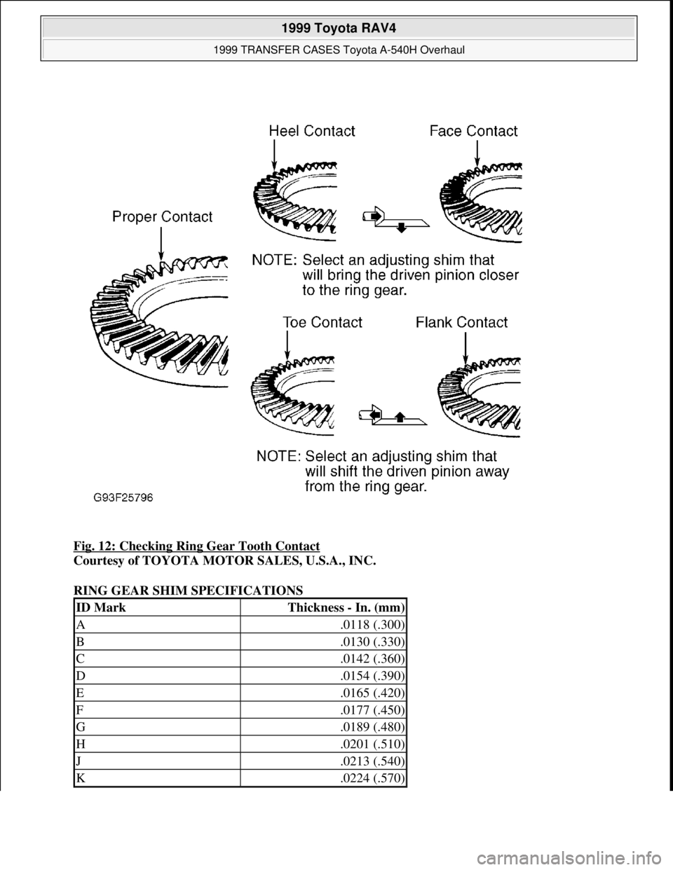
Fig. 12: Checking Ring Gear Tooth Contact
Courtesy of TOYOTA MOTOR SALES, U.S.A., INC.
RING GEAR SHIM SPECIFICATIONS
ID MarkThickness - In. (mm)
A.0118 (.300)
B.0130 (.330)
C.0142 (.360)
D.0154 (.390)
E.0165 (.420)
F.0177 (.450)
G.0189 (.480)
H.0201 (.510)
J.0213 (.540)
K.0224 (.570)
1999 Toyota RAV4
1999 TRANSFER CASES Toyota A-540H Overhaul
Microsoft
Sunday, November 22, 2009 10:49:16 AMPage 18 © 2005 Mitchell Repair Information Company, LLC.
Page 1419 of 1632
6. Remove right case. Remove ring gear mounting case and center differential case. Remove driven pinion
bearing cage assembly. Using Oil Seal Puller (09308-00010), remove outer race and plate washer.
7. Using Bearing Replacer (09316-60010), install NEW oil seal. Oil seal depth is .12" (3 mm). Coat lip of
oil seal with grease. Install plate washer. Using Bearing Replacer (09316-60010) and an arbor press,
install left case bearing outer race.
8. Coat "O" ring with gear oil and install on driven pinion bearing cage assembly. Install driven pinion
bearing cage with adjusting shim to transfer left case. Install 6 bolts. Tighten bolts to 29 ft. lbs. (39 N.m).
Install ring gear mounting case and center differential case.
9. Install NEW apply gasket to left case. Coat "O" ring with gear oil. Install "O" ring to oil pump strainer.
Install strainer to right case. Install bolts. Tighten to 48 INCH lbs. (5.4 N.m) Install oil pump driven gear.
Apply Sealant (Three Bond 1281) to left case. Install right case as soon as seal packing is applied. Install
right case to left case. Install 10 bolts. Tighten to 32 ft. lbs. (44 N.m). Check total preload as shown in
step 3 .
10. Install lock plate so projection from lock plate fits properly into groove of adjusting nut. When lock plate
cannot be installed, tighten adjusting nut smallest amount possible. Coat NEW "O" ring with gear oil.
Install "O" ring on lock bolt. Install and tighten lock nut to 62 INCH lbs. (7 N.m).
11. Apply Sealant (Three Bond 1281) to left case. Install inspection hole cover as soon as seal packing is
applied. Install hole cover to transfer left case. Install 3 bolts. Tighten to 12 ft. lbs. (16 N.m).
12. Coat NEW "O" ring with gear oil. Install "O" ring and NEW apply gasket. Install right case retainer to
transfer right case. Install 5 bolts. Tighten bolts to 21 ft. lbs. (29 N.m).
13. Install NEW oil seal in extension housing. Coat lip of oil seal with grease. Install NEW "O" ring in
extension housing. Install extension housing to driven pinion bearing cage. Install 4 bolts. Tighten to 18
ft. lbs. (25 N.m). Using a hammer, install dust deflector (if equipped). Install dynamic damper. Tighten to
18 ft. lbs. (25 N.m).
14. Install NEW "O" ring on speed sensor. Install speed sensor to transfer left case. Tighten to 48 INCH lbs.
(5.4 N.m). Install transfer mode selector lever, rod and lever guide (if equipped). Tighten 2 lever bolts to
96 INCH lbs. (11 N.m). Tighten guide bolt to 48 INCH lbs. (5.4 N.m).
TORQUE SPECIFICATIONS
TORQUE SPECIFICATIONS
ApplicationFt. Lbs. (N.m)
Case-To-Case Bolts33 (44)
Differential Switch30 (40)
Drain Plug29 (39)
Dynamic Damper Bolts18 (25)
Extension Housing Bolts18 (25)
Inspection Cover Bolts12 (16)
Pinion Bearing Cage Bolts29 (39)
Shift Fork Bolt12 (16)
1999 Toyota RAV4
1999 TRANSFER CASES Toyota A-540H Overhaul
Microsoft
Sunday, November 22, 2009 10:49:16 AMPage 19 © 2005 Mitchell Repair Information Company, LLC.
Page 1420 of 1632
1999 ENGINE PERFORMANCE
Vacuum Diagrams
INTRODUCTION
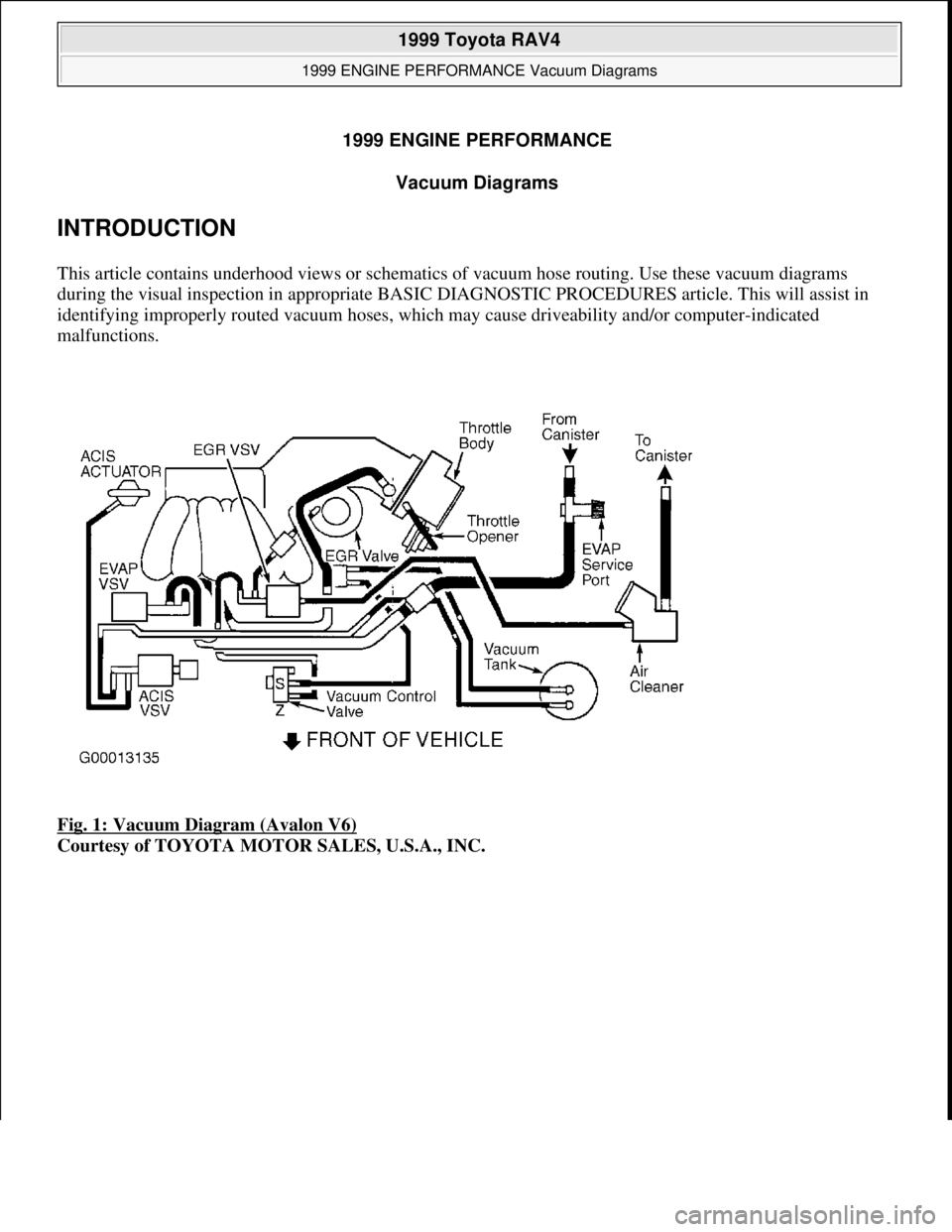
This article contains underhood views or schematics of vacuum hose routing. Use these vacuum diagrams
during the visual inspection in appropriate BASIC DIAGNOSTIC PROCEDURES article. This will assist in
identifying improperly routed vacuum hoses, which may cause driveability and/or computer-indicated
malfunctions.
Fig. 1: Vacuum Diagram (Avalon V6)
Courtesy of TOYOTA MOTOR SALES, U.S.A., INC.
1999 Toyota RAV4
1999 ENGINE PERFORMANCE Vacuum Diagrams
1999 Toyota RAV4
1999 ENGINE PERFORMANCE Vacuum Diagrams
Microsoft
Sunday, November 22, 2009 10:28:32 AMPage 1 © 2005 Mitchell Repair Information Company, LLC.
Microsoft
Sunday, November 22, 2009 10:28:36 AMPage 1 © 2005 Mitchell Repair Information Company, LLC.