TOYOTA RAV4 1996 Service Owner's Manual
Manufacturer: TOYOTA, Model Year: 1996, Model line: RAV4, Model: TOYOTA RAV4 1996Pages: 1632, PDF Size: 41.64 MB
Page 21 of 1632
Motor Relay Section
1. Check continuity between specified ABS control relay terminals. See Fig. 8 . Continuity should exist
between terminals A8-3 and A8-4. Continuity should not exist between terminals A8-1 and A8-2.
Measure resistance between terminals A8-3 and A8-4. Resistance should be 68 ohms. Replace motor
relay if it does not test as described.
2. If relay tests as described, apply battery voltage and ground between terminals A8-3 and A8-4. Check
continuity between terminals A8-1 and A8-2. Continuity should exist. If continuity is not as described,
replace ABS control rela
y.
1999 Toyota RAV4
1999-2000 BRAKES Anti-Lock - RAV4
Microsoft
Sunday, November 22, 2009 10:06:17 AMPage 21 © 2005 Mitchell Repair Information Company, LLC.
Page 22 of 1632
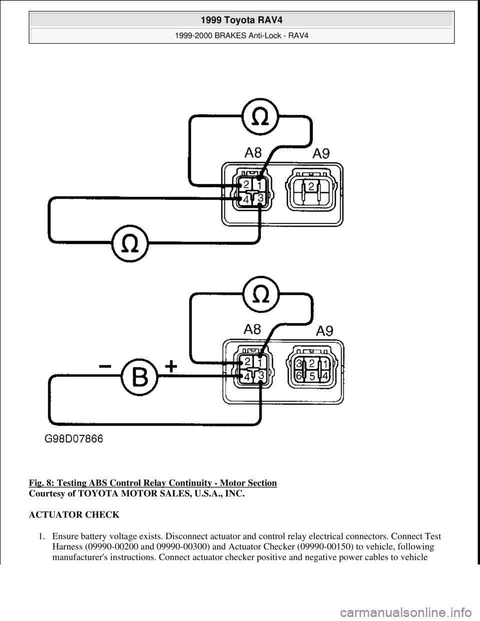
Fig. 8: Testing ABS Control Relay Continuity - Motor Section
Courtesy of TOYOTA MOTOR SALES, U.S.A., INC.
ACTUATOR CHECK
1. Ensure battery voltage exists. Disconnect actuator and control relay electrical connectors. Connect Test
Harness (09990-00200 and 09990-00300) and Actuator Checker (09990-00150) to vehicle, following
manufacturer's instructions. Connect actuator checker positive and ne
gative power cables to vehicle
1999 Toyota RAV4
1999-2000 BRAKES Anti-Lock - RAV4
Microsoft
Sunday, November 22, 2009 10:06:17 AMPage 22 © 2005 Mitchell Repair Information Company, LLC.
Page 23 of 1632
battery.
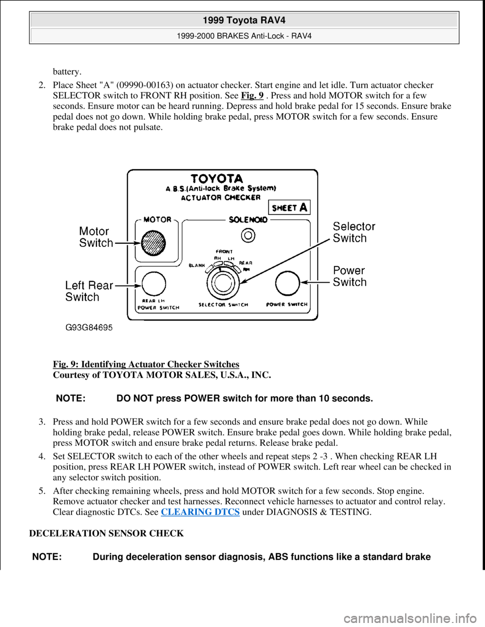
2. Place Sheet "A" (09990-00163) on actuator checker. Start engine and let idle. Turn actuator checker
SELECTOR switch to FRONT RH position. See Fig. 9
. Press and hold MOTOR switch for a few
seconds. Ensure motor can be heard running. Depress and hold brake pedal for 15 seconds. Ensure brake
pedal does not go down. While holding brake pedal, press MOTOR switch for a few seconds. Ensure
brake pedal does not pulsate.
Fig. 9: Identifying Actuator Checker Switches
Courtesy of TOYOTA MOTOR SALES, U.S.A., INC.
3. Press and hold POWER switch for a few seconds and ensure brake pedal does not go down. While
holding brake pedal, release POWER switch. Ensure brake pedal goes down. While holding brake pedal,
press MOTOR switch and ensure brake pedal returns. Release brake pedal.
4. Set SELECTOR switch to each of the other wheels and repeat steps 2 -3 . When checking REAR LH
position, press REAR LH POWER switch, instead of POWER switch. Left rear wheel can be checked in
any selector switch position.
5. After checking remaining wheels, press and hold MOTOR switch for a few seconds. Stop engine.
Remove actuator checker and test harnesses. Reconnect vehicle harnesses to actuator and control relay.
Clear diagnostic DTCs. See CLEARING DTCS
under DIAGNOSIS & TESTING.
DECELERATION SENSOR CHECK
NOTE: DO NOT press POWER switch for more than 10 seconds.
NOTE: During deceleration sensor diagnosis, ABS functions like a standard brake
1999 Toyota RAV4
1999-2000 BRAKES Anti-Lock - RAV4
Microsoft
Sunday, November 22, 2009 10:06:17 AMPage 23 © 2005 Mitchell Repair Information Company, LLC.
Page 24 of 1632
2-Door Models
1. Connect 3 "D" cell batteries in series, creating 4.5 volts. Connect VGS terminal of deceleration sensor to
positive (+) side of batteries. See Fig. 10
. Connect GGND terminal to negative (-) side of batteries.
2. Measure voltage between terminal GL1 and ground, and between terminal GL2 and ground at
deceleration sensor. Ensure sensor is within specifications. See DECELERATION SENSOR
SPECIFICATIONS . If sensor is not within specification, replace sensor.
DECELERATION SENSOR SPECIFICATIONS system.
TerminalPosition(1) Voltage
GL1Horizontal2.3
GL1Leaning Forward0-2.3
GL1Leaning Rearward2.3-4.5
GL2Horizontal2.3
GL2Leaning Forward2.3-4.5
GL2Leaning Rearward0-2.3
(1)Voltage value is approximate.
1999 Toyota RAV4
1999-2000 BRAKES Anti-Lock - RAV4
Microsoft
Sunday, November 22, 2009 10:06:17 AMPage 24 © 2005 Mitchell Repair Information Company, LLC.
Page 25 of 1632
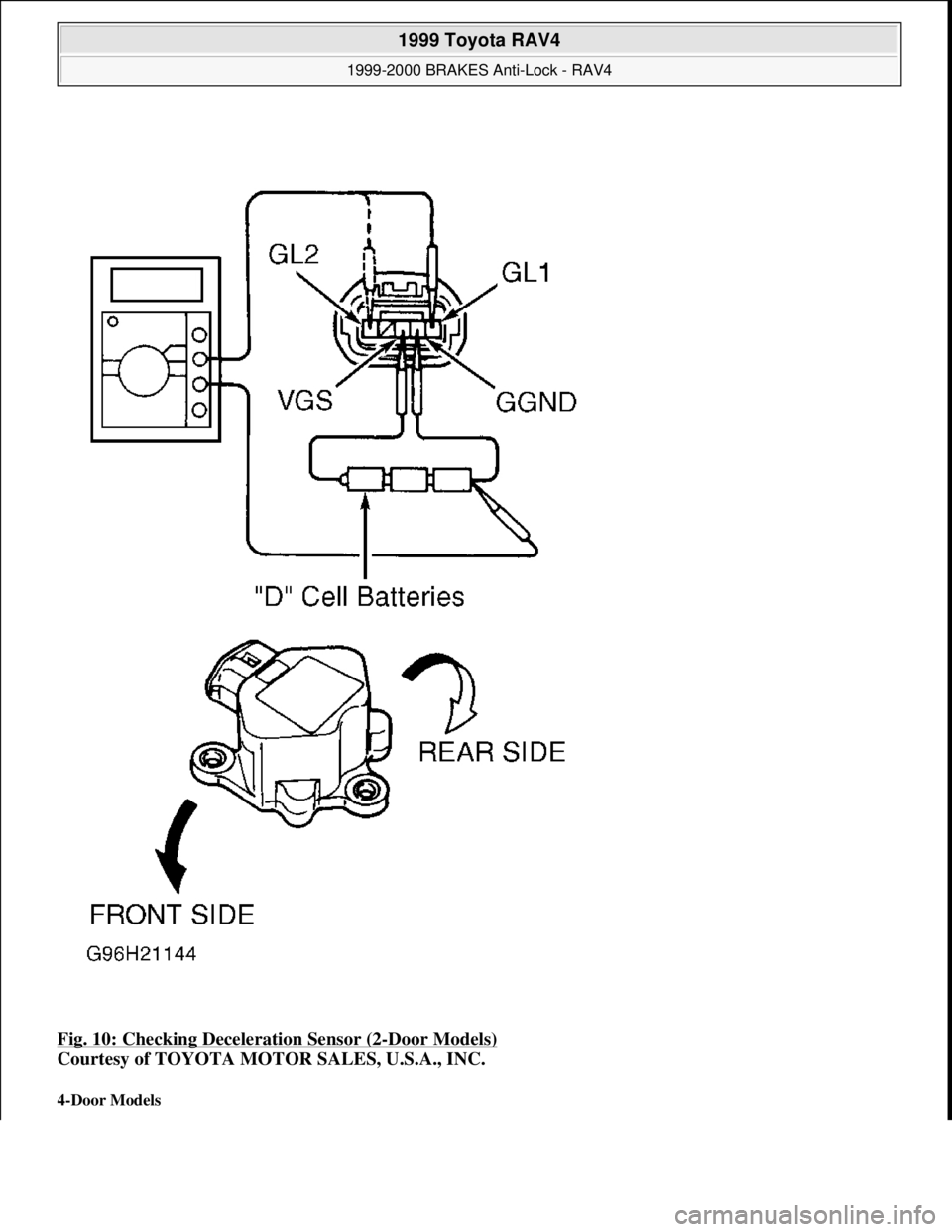
Fig. 10: Checking Deceleration Sensor (2-Door Models)
Courtesy of TOYOTA MOTOR SALES, U.S.A., INC.
4-Door Models
1999 Toyota RAV4
1999-2000 BRAKES Anti-Lock - RAV4
Microsoft
Sunday, November 22, 2009 10:06:17 AMPage 25 © 2005 Mitchell Repair Information Company, LLC.
Page 26 of 1632
1. Check charging system voltage. Ensure 10-14 volts is present. If charging system voltage is okay, go to
next step. If charging system voltage is not okay, check and repair charging system.
2. Turn ignition switch to ON position. Ensure ABS warning light comes on, then goes out after 3 seconds.
If ABS warning light does not illuminate, check fuse, bulb, and wiring harness. See ABS WARNING
LIGHT under DIAGNOSIS & TESTING. Turn ignition off.
3. Using a jumper wire, jumper terminals Ts and E
1 of DLC1. DLC1 is located in engine compartment on
left side of engine. See Fig. 2
. Ensure ABS warning light blinks 4 times per second. If ABS light does
not blink, go to ABS WARNING LIGHT
under DIAGNOSIS & TESTING. If ABS warning light
blinks, go to next step.
4. Using a floor jack, slowly jack up rear of vehicle. On vehicles with 215/70R16 tires, raise vehicle to a
height of 25.59-27.95" (650-710 mm). On vehicles with 235/60R16 tires, raise vehicle to a height of
26.38-28.74" (670-730 mm). If ABS warning light illuminates at specified height, check deceleration
sensor installation. If installation is okay, replace deceleration sensor. Lower vehicle.
5. Using a floor jack, slowly jack up front of vehicle. On vehicles with 215/70R16 tires, raise vehicle to a
height of 21.20-23.56" (550-610 mm). On vehicles with 235/60R16 tires, raise vehicle to a height of
22.44-24.80" (570-630 mm). If ABS warning light illuminates at specified height, check deceleration
sensor installation. If installation is okay, replace deceleration sensor. Lower vehicle.
6. Drive vehicle straight ahead at speed of 13 MPH or more. Lightly depress brake pedal. Ensure ABS
warning light pattern is normal (light blinks 4 times per second).
7. While driving vehicle straight ahead at speed of 13 MPH or more, moderately depress brake pedal.
Ensure ABS warning light illuminates in a solid pattern (light does not blink) while braking.
8. While driving vehicle straight ahead at speed of 13 MPH or more, firmly depress brake pedal. Ensure
ABS warning light illumination pattern changes from a solid pattern (light does not blink) to a normal
pattern (light blinks 4 times per second), then back to a solid pattern while braking.
9. If ABS warning light does not illuminate as described in steps 6 -8 , check deceleration sensor
installation. If installation is okay, replace deceleration sensor. Stop vehicle and turn ignition off. Remove
jumper wire from DLC1.
REMOVAL & INSTALLATION
ACTUATOR
Removal & Installation
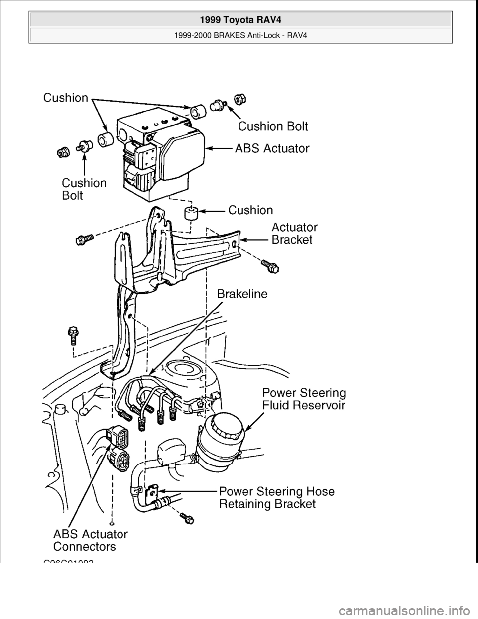
Turn ignition off. Disconnect brakelines attached to actuator. Remove power steering hose retaining bracket
bolt and power steering reservoir. Disconnect actuator electrical connectors. Remove bolts, nuts and washers.
Remove actuator assembly. Remove actuator from actuator bracket. Remove cushions and holders from NOTE: When measuring vehicle height in following steps, measure at center of
lower body of vehicle.
WARNING:Hydraulic system may be under high pressure. Use caution when opening
hydraulic system.
1999 Toyota RAV4
1999-2000 BRAKES Anti-Lock - RAV4
Microsoft
Sunday, November 22, 2009 10:06:17 AMPage 26 © 2005 Mitchell Repair Information Company, LLC.
Page 27 of 1632

actuator. See Fig. 11 . To install, reverse removal procedure. Bleed brake system. See BLEEDING BRAKE
SYSTEM .
1999 Toyota RAV4
1999-2000 BRAKES Anti-Lock - RAV4
Microsoft
Sunday, November 22, 2009 10:06:17 AMPage 27 © 2005 Mitchell Repair Information Company, LLC.
Page 28 of 1632
1999 Toyota RAV4
1999-2000 BRAKES Anti-Lock - RAV4
Microsoft
Sunday, November 22, 2009 10:06:17 AMPage 28 © 2005 Mitchell Repair Information Company, LLC.
Page 29 of 1632
Fig. 11: Exploded View of ABS Actuator
Courtesy of TOYOTA MOTOR SALES, U.S.A., INC.
ABS ECU
Removal & Installation
Ensure ignition is off. Disconnect negative battery cable. Access ABS ECU, located at right side of passenger
compartment. See Fig. 1
. Disconnect ABS ECU connectors. Remove ABS ECU from vehicle. To install,
reverse removal procedure.
FRONT SENSOR ROTOR
Removal & Installation
Front sensor is part of front hub. For removal and installation of front hub, see AXLE SHAFTS - RAV4 article
in DRIVE AXLES.
REAR SENSOR ROTOR
Removal & Installation
Rear sensor rotor is pressed onto axle shaft. For axle shaft removal and installation procedure, see AXLE
SHAFTS - RAV4 article in DRIVE AXLES.
FRONT WHEEL SPEED SENSORS
Removal & Installation
1. Raise and support front of vehicle. Remove front wheel. Remove inner fender panel. Disconnect wheel
speed sensor connector. Remove clamp bolts holding sensor harness to body, strut assembly and steering
knuckle.
2. Remove wheel speed sensor mounting bolt. Remove wheel speed sensor from steering knuckle. To
install, reverse removal procedure. Ensure wheel speed sensor is flat against knuckle when bolt is
tightened. Tighten wheel speed sensor mounting bolt to specification. See TORQUE
SPECIFICATIONS .
REAR WHEEL SPEED SENSORS
Removal & Installation
1. Remove rear seat cushion and side trim panel. Raise and support vehicle. Remove wheel. Unplug wheel
speed sensor connector and remove wire harness from grommet. Disconnect parking brake cable from
suspension arm. Remove clamp bolts holding sensor wiring harness to body and suspension arm.
2. Remove wheel speed sensor. To install, reverse removal procedure. Ensure wheel speed sensor is flat NOTE: Front hub must be removed to service sensor rotor.
1999 Toyota RAV4
1999-2000 BRAKES Anti-Lock - RAV4
Microsoft
Sunday, November 22, 2009 10:06:17 AMPage 29 © 2005 Mitchell Repair Information Company, LLC.
Page 30 of 1632
against knuckle when bolt is tightened. Tighten wheel speed sensor and brake components to
specification. See TORQUE SPECIFICATIONS
.
ADJUSTMENTS
BRAKE BOOSTER PUSH ROD
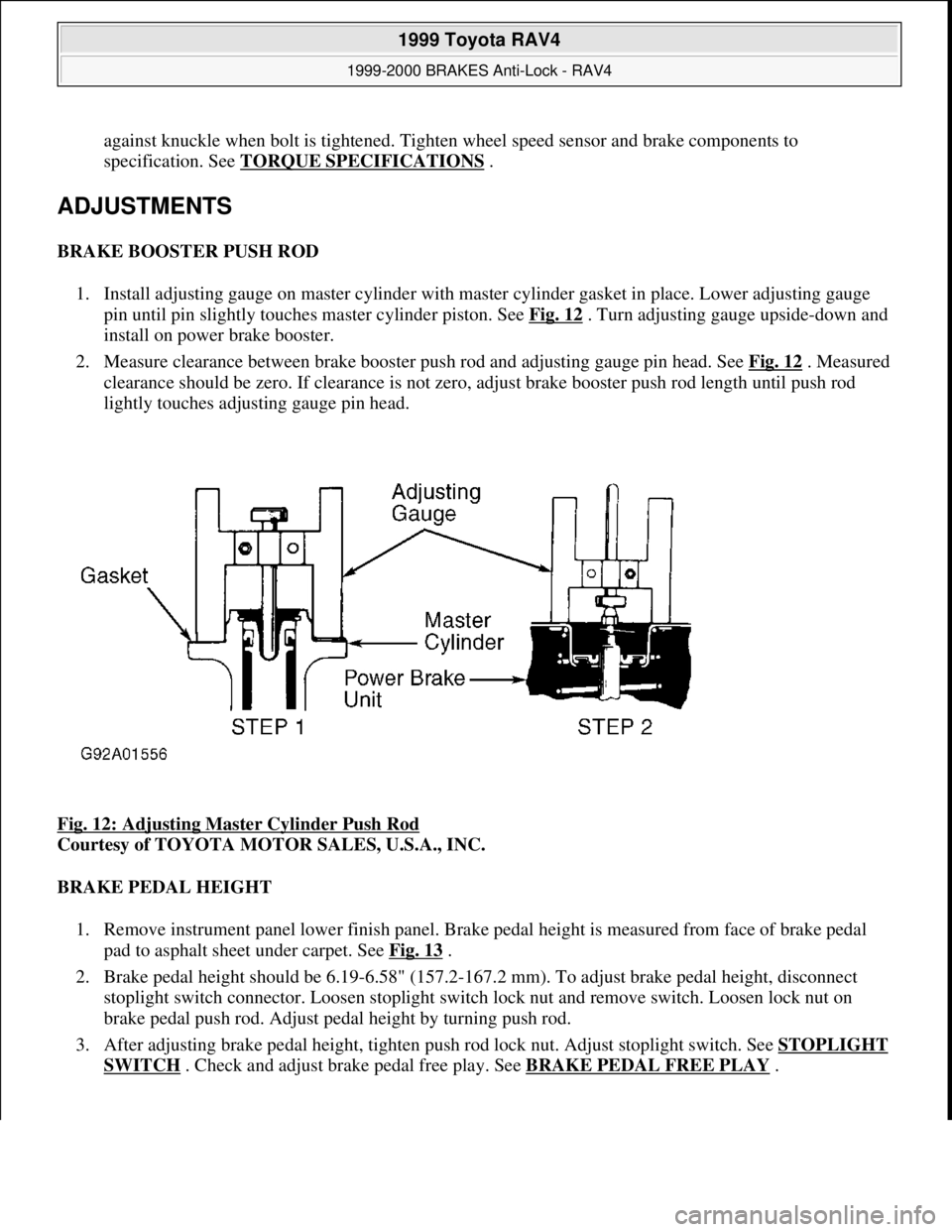
1. Install adjusting gauge on master cylinder with master cylinder gasket in place. Lower adjusting gauge
pin until pin slightly touches master cylinder piston. See Fig. 12
. Turn adjusting gauge upside-down and
install on power brake booster.
2. Measure clearance between brake booster push rod and adjusting gauge pin head. See Fig. 12
. Measured
clearance should be zero. If clearance is not zero, adjust brake booster push rod length until push rod
lightly touches adjusting gauge pin head.
Fig. 12: Adjusting Master Cylinder Push Rod
Courtesy of TOYOTA MOTOR SALES, U.S.A., INC.
BRAKE PEDAL HEIGHT
1. Remove instrument panel lower finish panel. Brake pedal height is measured from face of brake pedal
pad to asphalt sheet under carpet. See Fig. 13
.
2. Brake pedal height should be 6.19-6.58" (157.2-167.2 mm). To adjust brake pedal height, disconnect
stoplight switch connector. Loosen stoplight switch lock nut and remove switch. Loosen lock nut on
brake pedal push rod. Adjust pedal height by turning push rod.
3. After adjusting brake pedal height, tighten push rod lock nut. Adjust stoplight switch. See STOPLIGHT
SWITCH . Check and adjust brake pedal free play. See BRAKE PEDAL FREE PLAY.
1999 Toyota RAV4
1999-2000 BRAKES Anti-Lock - RAV4
Microsoft
Sunday, November 22, 2009 10:06:17 AMPage 30 © 2005 Mitchell Repair Information Company, LLC.