TOYOTA RAV4 1996 Service Repair Manual
Manufacturer: TOYOTA, Model Year: 1996, Model line: RAV4, Model: TOYOTA RAV4 1996Pages: 1632, PDF Size: 41.64 MB
Page 531 of 1632
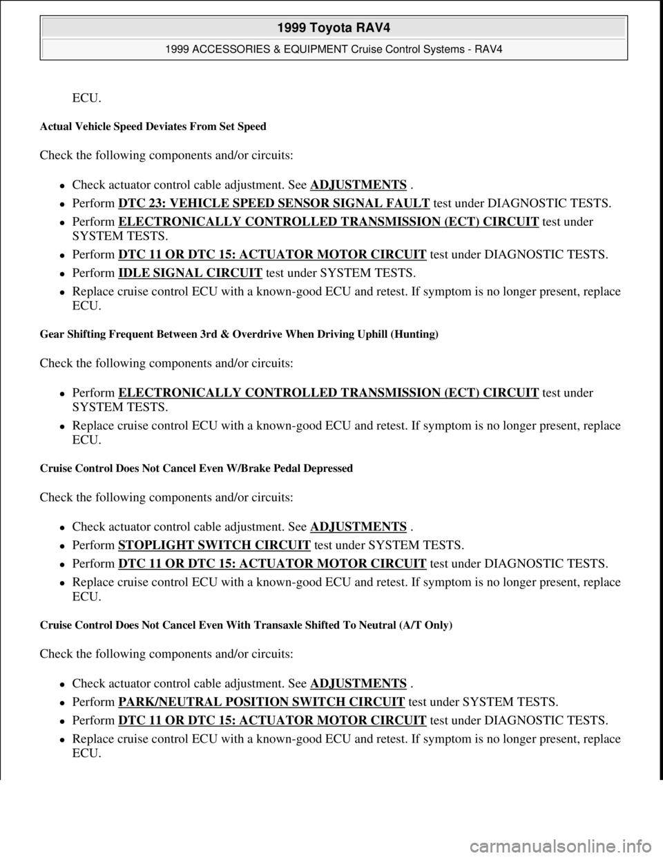
ECU.
Actual Vehicle Speed Deviates From Set Speed
Check the following components and/or circuits:
Check actuator control cable adjustment. See ADJUSTMENTS .
Perform DTC 23: VEHICLE SPEED SENSOR SIGNAL FAULT test under DIAGNOSTIC TESTS.
Perform ELECTRONICALLY CONTROLLED TRANSMISSION (ECT) CIRCUIT test under
SYSTEM TESTS.
Perform DTC 11 OR DTC 15: ACTUATOR MOTOR CIRCUIT test under DIAGNOSTIC TESTS.
Perform IDLE SIGNAL CIRCUIT test under SYSTEM TESTS.
Replace cruise control ECU with a known-good ECU and retest. If symptom is no longer present, replace
ECU.
Gear Shifting Frequent Between 3rd & Overdrive When Driving Uphill (Hunting)
Check the following components and/or circuits:
Perform ELECTRONICALLY CONTROLLED TRANSMISSION (ECT) CIRCUIT test under
SYSTEM TESTS.
Replace cruise control ECU with a known-good ECU and retest. If symptom is no longer present, replace
ECU.
Cruise Control Does Not Cancel Even W/Brake Pedal Depressed
Check the following components and/or circuits:
Check actuator control cable adjustment. See ADJUSTMENTS .
Perform STOPLIGHT SWITCH CIRCUIT test under SYSTEM TESTS.
Perform DTC 11 OR DTC 15: ACTUATOR MOTOR CIRCUIT test under DIAGNOSTIC TESTS.
Replace cruise control ECU with a known-good ECU and retest. If symptom is no longer present, replace
ECU.
Cruise Control Does Not Cancel Even With Transaxle Shifted To Neutral (A/T Only)
Check the following components and/or circuits:
Check actuator control cable adjustment. See ADJUSTMENTS .
Perform PARK/NEUTRAL POSITION SWITCH CIRCUIT test under SYSTEM TESTS.
Perform DTC 11 OR DTC 15: ACTUATOR MOTOR CIRCUIT test under DIAGNOSTIC TESTS.
Replace cruise control ECU with a known-good ECU and retest. If symptom is no longer present, replace
ECU.
1999 Toyota RAV4
1999 ACCESSORIES & EQUIPMENT Cruise Control Systems - RAV4
Microsoft
Sunday, November 22, 2009 10:52:01 AMPage 7 © 2005 Mitchell Repair Information Company, LLC.
Page 532 of 1632
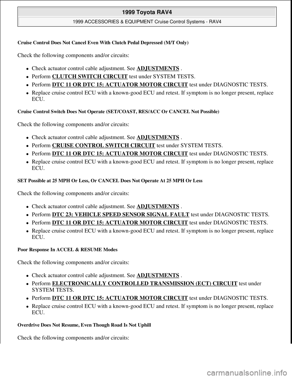
Cruise Control Does Not Cancel Even With Clutch Pedal Depressed (M/T Only)
Check the following components and/or circuits:
Check actuator control cable adjustment. See ADJUSTMENTS .
Perform CLUTCH SWITCH CIRCUIT test under SYSTEM TESTS.
Perform DTC 11 OR DTC 15: ACTUATOR MOTOR CIRCUIT test under DIAGNOSTIC TESTS.
Replace cruise control ECU with a known-good ECU and retest. If symptom is no longer present, replace
ECU.
Cruise Control Switch Does Not Operate (SET/COAST, RES/ACC Or CANCEL Not Possible)
Check the following components and/or circuits:
Check actuator control cable adjustment. See ADJUSTMENTS .
Perform CRUISE CONTROL SWITCH CIRCUIT test under SYSTEM TESTS.
Perform DTC 11 OR DTC 15: ACTUATOR MOTOR CIRCUIT test under DIAGNOSTIC TESTS.
Replace cruise control ECU with a known-good ECU and retest. If symptom is no longer present, replace
ECU.
SET Possible at 25 MPH Or Less, Or CANCEL Does Not Operate At 25 MPH Or Less
Check the following components and/or circuits:
Check actuator control cable adjustment. See ADJUSTMENTS .
Perform DTC 23: VEHICLE SPEED SENSOR SIGNAL FAULT test under DIAGNOSTIC TESTS.
Perform DTC 11 OR DTC 15: ACTUATOR MOTOR CIRCUIT test under DIAGNOSTIC TESTS.
Replace cruise control ECU with a known-good ECU and retest. If symptom is no longer present, replace
ECU.
Poor Response In ACCEL & RESUME Modes
Check the following components and/or circuits:
Check actuator control cable adjustment. See ADJUSTMENTS .
Perform ELECTRONICALLY CONTROLLED TRANSMISSION (ECT) CIRCUIT test under
SYSTEM TESTS.
Perform DTC 11 OR DTC 15: ACTUATOR MOTOR CIRCUIT test under DIAGNOSTIC TESTS.
Replace cruise control ECU with a known-good ECU and retest. If symptom is no longer present, replace
ECU.
Overdrive Does Not Resume, Even Though Road Is Not Uphill
Check the following components and/or circuits:
1999 Toyota RAV4
1999 ACCESSORIES & EQUIPMENT Cruise Control Systems - RAV4
Microsoft
Sunday, November 22, 2009 10:52:01 AMPage 8 © 2005 Mitchell Repair Information Company, LLC.
Page 533 of 1632
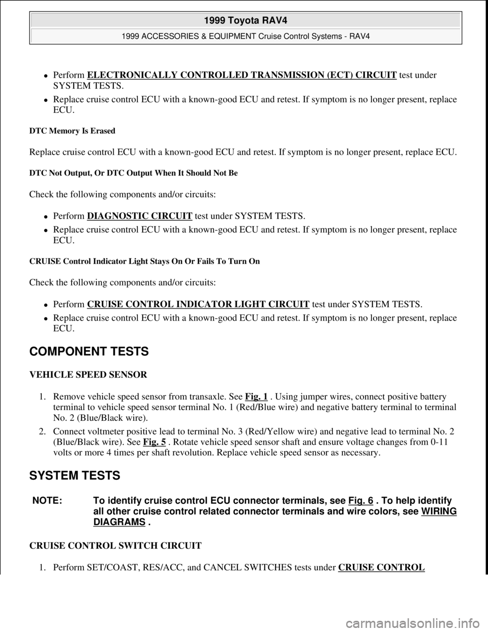
Perform ELECTRONICALLY CONTROLLED TRANSMISSION (ECT) CIRCUIT test under
SYSTEM TESTS.
Replace cruise control ECU with a known-good ECU and retest. If symptom is no longer present, replace
ECU.
DTC Memory Is Erased
Replace cruise control ECU with a known-good ECU and retest. If symptom is no longer present, replace ECU.
DTC Not Output, Or DTC Output When It Should Not Be
Check the following components and/or circuits:
Perform DIAGNOSTIC CIRCUIT test under SYSTEM TESTS.
Replace cruise control ECU with a known-good ECU and retest. If symptom is no longer present, replace
ECU.
CRUISE Control Indicator Light Stays On Or Fails To Turn On
Check the following components and/or circuits:
Perform CRUISE CONTROL INDICATOR LIGHT CIRCUIT test under SYSTEM TESTS.
Replace cruise control ECU with a known-good ECU and retest. If symptom is no longer present, replace
ECU.
COMPONENT TESTS
VEHICLE SPEED SENSOR
1. Remove vehicle speed sensor from transaxle. See Fig. 1
. Using jumper wires, connect positive battery
terminal to vehicle speed sensor terminal No. 1 (Red/Blue wire) and negative battery terminal to terminal
No. 2 (Blue/Black wire).
2. Connect voltmeter positive lead to terminal No. 3 (Red/Yellow wire) and negative lead to terminal No. 2
(Blue/Black wire). See Fig. 5
. Rotate vehicle speed sensor shaft and ensure voltage changes from 0-11
volts or more 4 times per shaft revolution. Replace vehicle speed sensor as necessary.
SYSTEM TESTS
CRUISE CONTROL SWITCH CIRCUIT
1. Perform SET/COAST, RES/ACC, and CANCEL SWITCHES tests under CRUISE CONTROL
NOTE: To identify cruise control ECU connector terminals, see Fig. 6 . To help identify
all other cruise control related connector terminals and wire colors, see WIRING
DIAGRAMS .
1999 Toyota RAV4
1999 ACCESSORIES & EQUIPMENT Cruise Control Systems - RAV4
Microsoft
Sunday, November 22, 2009 10:52:01 AMPage 9 © 2005 Mitchell Repair Information Company, LLC.
Page 534 of 1632
FUNCTION TEST under TROUBLE SHOOTING. If SET/COAST, RES/ACC or CANCEL input
signals are not as specified, go to next step. If input signals are as specified, no problem is indicated at
this time. Fault may be intermittent. If sent here from SYMPTOM DIAGNOSIS, perform next test listed,
go to next step. If input signals are as specified, no problem is indicated at this time. Fault may be
intermittent. If sent here from SYMPTOM DIAGNOSIS, perform next test listed.
2. Remove cruise control ECU with connector attached. See Fig. 1
. Turn ignition switch to ON position.
Backprobing connector, measure voltage between cruise control ECU connector terminal No. 10
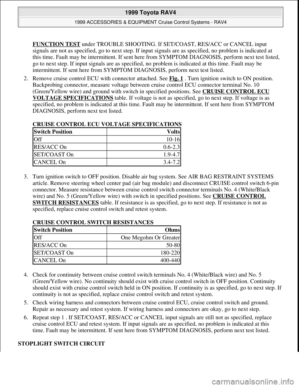
(Green/Yellow wire) and ground with switch in specified positions. See CRUISE CONTROL ECU
VOLTAGE SPECIFICATIONS table. If voltage is not as specified, go to next step. If voltage is as
specified, no problem is indicated at this time. Fault may be intermittent. If sent here from SYMPTOM
DIAGNOSIS, perform next test listed.
CRUISE CONTROL ECU VOLTAGE SPECIFICATIONS
3. Turn ignition switch to OFF position. Disable air bag system. See AIR BAG RESTRAINT SYSTEMS
article. Remove steering wheel center pad (air bag module) and disconnect CRUISE control switch 6-pin
connector. Measure resistance between cruise control switch connector terminals No. 4 (White/Black
wire) and No. 5 (Green/Yellow wire) with switch in specified positions. See CRUISE CONTROL
SWITCH RESISTANCES table. If resistance is as specified, go to next step. If resistance is not as
specified, replace cruise control switch and retest system.
CRUISE CONTROL SWITCH RESISTANCES
4. Check for continuity between cruise control switch terminals No. 4 (White/Black wire) and No. 5
(Green/Yellow wire). No continuity should exist with cruise control switch in OFF position. Continuity
should exist with cruise control switch held in ON position. If continuity is as specified, go to next step. I
f
continuity is not as specified, replace cruise control switch and retest system.
5. Check wiring harness and connectors between cruise control ECU, cruise control switch and ground.
Repair as necessary and retest system. If wiring harness and connectors are okay, go to next step.
6. Repeat step 1 . If SET/COAST, RES/ACC or CANCEL input signals are still not as specified, replace
cruise control ECU and retest system. If input signals are as specified, no problem is indicated at this
time. Fault may be intermittent. If sent here from SYMPTOM DIAGNOSIS, perform next test listed.
STOPLIGHT SWITCH CIRCUIT
Switch PositionVolts
Off10-16
RES/ACC On0.6-2.3
SET/COAST On1.9-4.7
CANCEL On3.4-7.2
Switch PositionOhms
OffOne Megohm Or Greater
RES/ACC On50-80
SET/COAST On180-220
CANCEL On400-440
1999 Toyota RAV4
1999 ACCESSORIES & EQUIPMENT Cruise Control Systems - RAV4
Microsoft
Sunday, November 22, 2009 10:52:01 AMPage 10 © 2005 Mitchell Repair Information Company, LLC.
Page 535 of 1632
1. Check stoplight operation. If stoplight operation is okay, go to next step. If stoplights DO NOT operate
correctly, check and repair stoplight system as necessary. See WIRING DIAGRAMS
.
2. Perform CANCEL SWITCHES test under CRUISE CONTROL FUNCTION TEST
under TROUBLE
SHOOTING. If stoplight input signal is not as specified, go to next step. If stoplight input signal is as
specified, no problem is indicated at this time. Fault may be intermittent. If sent here from SYMPTOM
DIAGNOSIS, perform next test listed.
3. Remove cruise control ECU with connector attached. See Fig. 1
. Turn ignition switch to ON position.
Backprobing cruise control ECU connector, measure voltage between ground and cruise control ECU
connector terminal No. 2 (Green/White wire). With brake pedal depressed, battery voltage should exist.
With brake pedal released, voltage should be less than one volt. If voltage is not as specified, go to next
step. If voltage is as specified, no problem is indicated at this time. Fault may be intermittent. If sent here
from SYMPTOM DIAGNOSIS, perform next test listed.
4. Check for open circuit in wiring harness and connectors between cruise control ECU and stoplight switch.
Repair as necessary and retest system. If wiring harness and connectors are okay, replace cruise control
ECU and retest system.
IDLE SIGNAL CIRCUIT
1. Remove cruise control ECU with connector attached. Disconnect Engine Control Module (ECM) 16-pin
connector. ECM is located behind bottom center of instrument panel, in front of console. Turn ignition
switch to ON position. Backprobing connector, measure voltage between ground and cruise control ECU
connector terminal No. 13 (Blue wire).
2. With throttle valve fully open, battery voltage should exist. With throttle valve fully closed, voltage
should be less than 2 volts. If voltage is not as specified, go to next step. If voltage is as specified, no
problem is indicated at this time. Fault may be intermittent. If sent here from SYMPTOM DIAGNOSIS,
perform next test listed.
3. Check wiring harness and connectors between ECM and TP sensor. Repair as necessary and retest
system. If wiring harness and connectors are okay, go to next step.
4. Disconnect TP sensor 3-pin Black connector. Measure resistance between TP sensor connector terminals
No. 2 (Brown wire) and No. 3 (Blue/Red wire). Resistance should be 2000-10,200 ohms with throttle
valve fully opened, and 200-6300 ohms with throttle valve fully closed. If resistance is as specified, go to
next step. If resistance is not as specified, replace TP sensor and retest system.
5. Check wiring harness and connectors between cruise control ECU and TP sensor, and between TP sensor
and ground. Repair as necessary and retest system. If wiring harness and connectors are okay, replace
cruise control ECU and retest system.
ELECTRONICALLY CONTROLLED TRANSMISSION (ECT) CIRCUIT
1. Start engine and bring to operating temperature. Drive vehicle and ensure overdrive operation is turned on
and off when overdrive ON-OFF switch is operated. If overdrive switch is okay, go to next step. If
overdrive switch is not okay, see appropriate ELECTRONIC CONTROLS article in AUTOMATIC NOTE: Ensure Throttle Position (TP) sensor circuit is operating as designed, and no
fault codes are present for TP sensor circuit. See appropriate ON-VEHICLE
ADJUSTMENTS article in ENGINE PERFORMANCE.
1999 Toyota RAV4
1999 ACCESSORIES & EQUIPMENT Cruise Control Systems - RAV4
Microsoft
Sunday, November 22, 2009 10:52:01 AMPage 11 © 2005 Mitchell Repair Information Company, LLC.
Page 536 of 1632
TRANSMISSIONS article.
2. Turn ignition switch to OFF position. Remove cruise control ECU and disconnect connector. See Fig. 1
.
Turn ignition switch to ON position. Using voltmeter positive lead, backprobe cruise control ECU
harness connector terminal No. 14 (Yellow/Black wire) with negative lead to ground. If battery voltage is
present, go to next step. If battery voltage is not present, go to step 5 .
3. Turn ignition switch to OFF position. Reconnect cruise control ECU connector. Using voltmeter positive
lead, backprobe cruise control ECU connector terminal No. 6 (Pink wire) with negative lead to ground.
Bring engine to operating temperature and test drive vehicle with overdrive switch moved from ON to
OFF position. With overdrive in OFF position, voltage should be less than .5 volt. With overdrive in ON
position, battery voltage should be present. If voltage is not as specified, go to next step. If voltage is as
specified, no problem is indicated at this time. Fault may be intermittent. If sent here from SYMPTOM
DIAGNOSIS, perform next test listed.
4. Check wiring harness and connectors between cruise control ECU terminal No. 6 (Pink wire) and
electronically controlled transmission solenoid. Repair as necessary. If wiring harness and connectors are
okay, replace cruise control ECU and retest system.
5. Check wiring harness and connectors between cruise control ECU connector terminal No. 14
(Yellow/Black wire) and Engine Control Module (ECM) 22-pin connector terminal No. 20
(Yellow/Black wire). Repair as necessary. If wiring harness and connectors are okay, replace cruise
control ECU and retest system.
PARK/NEUTRAL POSITION SWITCH CIRCUIT
1. Ensure starting system is operating normally. Check for starting system problems and repair as necessary.
See STARTERS article in STARTING & CHARGING SYSTEMS. If starting system is okay, go to next
step.
2. Perform park/neutral position switch test. See CANCEL SWITCHES test in CRUISE CONTROL
FUNCTION TEST under TROUBLE SHOOTING. If park/neutral position switch input signal is not as
specified, go to next step. If park/neutral position switch input signal is as specified, no problem is
indicated at this time. Fault may be intermittent. If sent here from SYMPTOM DIAGNOSIS, perform
next test listed.
3. Remove cruise control ECU with connector attached. See Fig. 1
. Turn ignition switch to ON position.
Backprobing connector, measure voltage between ground and terminal No. 3 (Blue/Black wire) at cruise
control ECU connector. With shift lever in Drive, battery voltage should be present. With shift lever in
any other position, voltage should be less than one volt. If voltage is not as specified, go to next step. If
voltage is as specified, no problem is indicated at this time. Fault may be intermittent. If sent here from
SYMPTOM DIAGNOSIS, perform next test listed.
4. Check wiring harness and connectors between cruise control ECU and park/neutral position switch.
Repair as necessary. If wiring harness and connectors are okay, replace cruise control ECU and retest
system.
CLUTCH SWITCH CIRCUIT
1. Ensure starting system is operating normally. Check for starting system problems and repair as necessary.
If starting system is okay, go to next step.
2. Perform clutch switch position test. See CANCEL SWITCHES test in CRUISE CONTROL
1999 Toyota RAV4
1999 ACCESSORIES & EQUIPMENT Cruise Control Systems - RAV4
Microsoft
Sunday, November 22, 2009 10:52:01 AMPage 12 © 2005 Mitchell Repair Information Company, LLC.
Page 537 of 1632
FUNCTION TEST under TROUBLE SHOOTING. If clutch switch input signal is not as specified, go to
next step. If clutch switch input signal is as specified, no problem is indicated at this time. Fault may be
intermittent. If sent here from SYMPTOM DIAGNOSIS, perform next test listed.
3. Remove cruise control ECU with connector attached. See Fig. 1
. Turn ignition switch to ON position.
Using voltmeter positive lead, backprobe cruise control ECU connector terminal No. 3 (Blue/Black wire)
with negative lead to ground. With clutch pedal depressed, battery voltage should exist. With clutch pedal
released, voltage should be less than one volt. If voltage is not as specified, go to next step. If voltage is
as specified, no problem is indicated at this time. Fault may be intermittent. If sent here from SYMPTOM
DIAGNOSIS, perform next test listed.
4. Check wiring harness and connectors between cruise control ECU and TURN & GAUGE fuses in
instrument panel junction block. Repair as necessary. If wiring harness and connectors are okay, replace
cruise control ECU and retest system.
CRUISE CONTROL ECU POWER SOURCE CIRCUIT
1. Locate ECU-IG (10-amp) fuse in instrument panel junction block. See Fig. 1
. Remove ECU-IG fuse and
ensure fuse continuity. If fuse is okay, go to next step. If fuse is not okay, check for short between cruise
control ECU connector terminal No. 9 (Black/Yellow wire) and ECU-IG fuse.
2. Remove cruise control ECU with connector attached. See Fig. 1
. Turn ignition switch to ON position.
Using voltmeter, backprobe between cruise control ECU connector terminals No. 9 (Black/Yellow wire)
and No. 16 (White/Black wire). If battery voltage is not present, go to next step. If battery voltage is
present, no problem is indicated at this time. Fault may be intermittent. If sent here from SYMPTOM
DIAGNOSIS, perform next test listed.
3. Turn ignition switch to OFF position. Backprobing connector, measure resistance between ground and
terminal No. 16 (White/Black wire) at cruise control ECU connector. If resistance is less than one ohm,
check wiring harness or connector between cruise control ECU connector and battery. Repair as
necessary and retest system. If resistance is one ohm or more, repair wiring harness or connector between
cruise control ECU connector terminal No. 16 (White/Black wire) and ground. Retest system.
CRUISE CONTROL INDICATOR LIGHT CIRCUIT
1. Turn ignition switch to ON position. Backprobing connector, measure voltage between ground and
terminal No. 4 (Green/Red wire) at cruise control ECU connector. With cruise control switch in OFF
position, battery voltage should be present. With cruise control switch in ON position, voltage should be
less than 1.2 volts.
2. If voltage is as specified, no problem is indicated at this time. Fault may be intermittent. If sent here from
SYMPTOM DIAGNOSIS, perform next test listed. If voltage is not as specified, check instrument
cluster. See appropriate INSTRUMENT PANELS article. Repair as necessary. If instrument cluster is
okay, replace cruise control ECU and retest system.
DIAGNOSTIC CIRCUIT
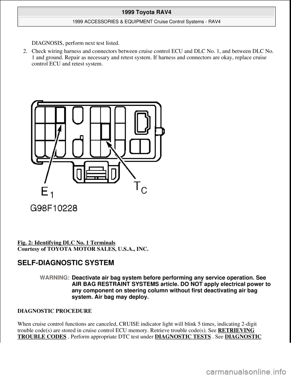
1. Locate Data Link Connector (DLC) No. 1 in right side of engine compartment, near shock tower.
Connect voltmeter positive lead to terminal Tc and negative lead to terminal E1. See Fig. 2
. Turn
ignition switch to ON position. If battery voltage is not present, go to next step. If battery voltage is
present, no problem is indicated at this time. Fault ma
y be intermittent. If sent here from SYMPTOM
1999 Toyota RAV4
1999 ACCESSORIES & EQUIPMENT Cruise Control Systems - RAV4
Microsoft
Sunday, November 22, 2009 10:52:01 AMPage 13 © 2005 Mitchell Repair Information Company, LLC.
Page 538 of 1632
DIAGNOSIS, perform next test listed.
2. Check wiring harness and connectors between cruise control ECU and DLC No. 1, and between DLC No.
1 and ground. Repair as necessary and retest system. If harness and connectors are okay, replace cruise
control ECU and retest system.
Fig. 2: Identifying DLC No. 1 Terminals
Courtesy of TOYOTA MOTOR SALES, U.S.A., INC.
SELF-DIAGNOSTIC SYSTEM
DIAGNOSTIC PROCEDURE
When cruise control functions are canceled, CRUISE indicator light will blink 5 times, indicating 2-digit
trouble code(s) are stored in cruise control ECU memory. Retrieve trouble code(s). See RETRIEVING
TROUBLE CODES . Perform appropriate DTC test under DIAGNOSTIC TESTS . See DIAGNOSTIC
WARNING:Deactivate air bag system before performing any service operation. See
AIR BAG RESTRAINT SYSTEMS article. DO NOT apply electrical power to
any component on steering column without first deactivating air bag
system. Air bag may deploy.
1999 Toyota RAV4
1999 ACCESSORIES & EQUIPMENT Cruise Control Systems - RAV4
Microsoft
Sunday, November 22, 2009 10:52:01 AMPage 14 © 2005 Mitchell Repair Information Company, LLC.
Page 539 of 1632
TROUBLE CODE DEFINITIONS table.
If a fault or symptom is present, but no trouble codes were set, perform CRUISE CONTROL FUNCTION
TEST under TROUBLE SHOOTING. Cruise control function test will cause CRUISE indicator light to display
a one-digit function code if circuit tested is okay. After performing cruise control function test, if system still
does not operate properly and no self-diagnostic trouble codes are present, perform SYMPTOM DIAGNOSIS
under TROUBLE SHOOTING.
READING TROUBLE CODES
Trouble codes are displayed as flashes of CRUISE indicator light. All trouble codes are 2-digit numbers. Cruise
control ECU outputs trouble codes from lowest to highest. These codes indicate current faults in system and
should be serviced in order of appearance. Pay careful attention to length of pauses in order to read codes
correctly. See Fig. 3
.
1999 Toyota RAV4
1999 ACCESSORIES & EQUIPMENT Cruise Control Systems - RAV4
Microsoft
Sunday, November 22, 2009 10:52:01 AMPage 15 © 2005 Mitchell Repair Information Company, LLC.
Page 540 of 1632
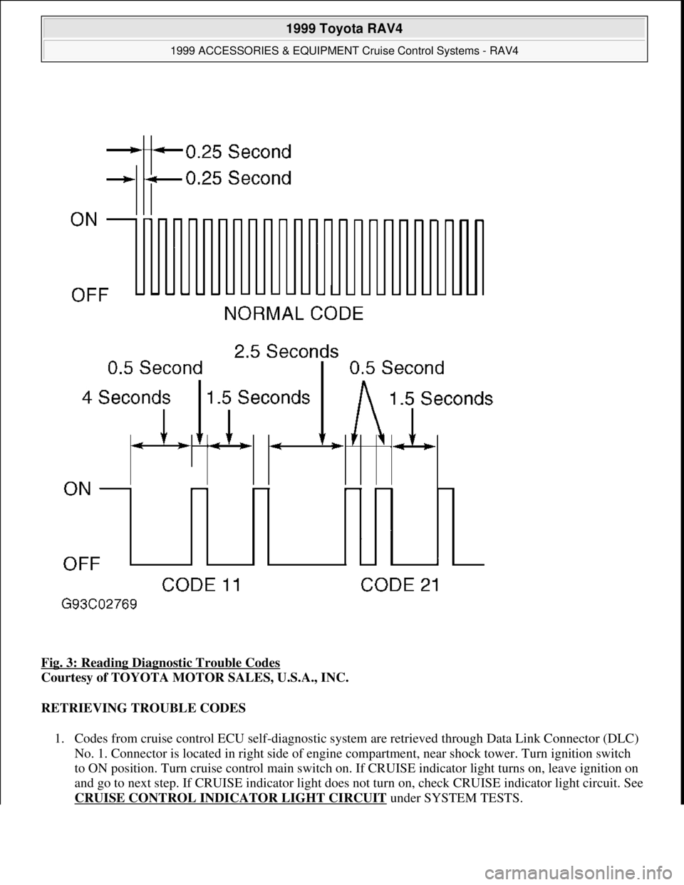
Fig. 3: Reading Diagnostic Trouble Codes
Courtesy of TOYOTA MOTOR SALES, U.S.A., INC.
RETRIEVING TROUBLE CODES
1. Codes from cruise control ECU self-diagnostic system are retrieved through Data Link Connector (DLC)
No. 1. Connector is located in right side of engine compartment, near shock tower. Turn ignition switch
to ON position. Turn cruise control main switch on. If CRUISE indicator light turns on, leave ignition on
and go to next step. If CRUISE indicator light does not turn on, check CRUISE indicator light circuit. See
CRUISE CONTROL INDICATOR LIGHT CIRCUIT
under SYSTEM TESTS.
1999 Toyota RAV4
1999 ACCESSORIES & EQUIPMENT Cruise Control Systems - RAV4
Microsoft
Sunday, November 22, 2009 10:52:01 AMPage 16 © 2005 Mitchell Repair Information Company, LLC.