TOYOTA RAV4 1996 Service Repair Manual
Manufacturer: TOYOTA, Model Year: 1996, Model line: RAV4, Model: TOYOTA RAV4 1996Pages: 1632, PDF Size: 41.64 MB
Page 691 of 1632
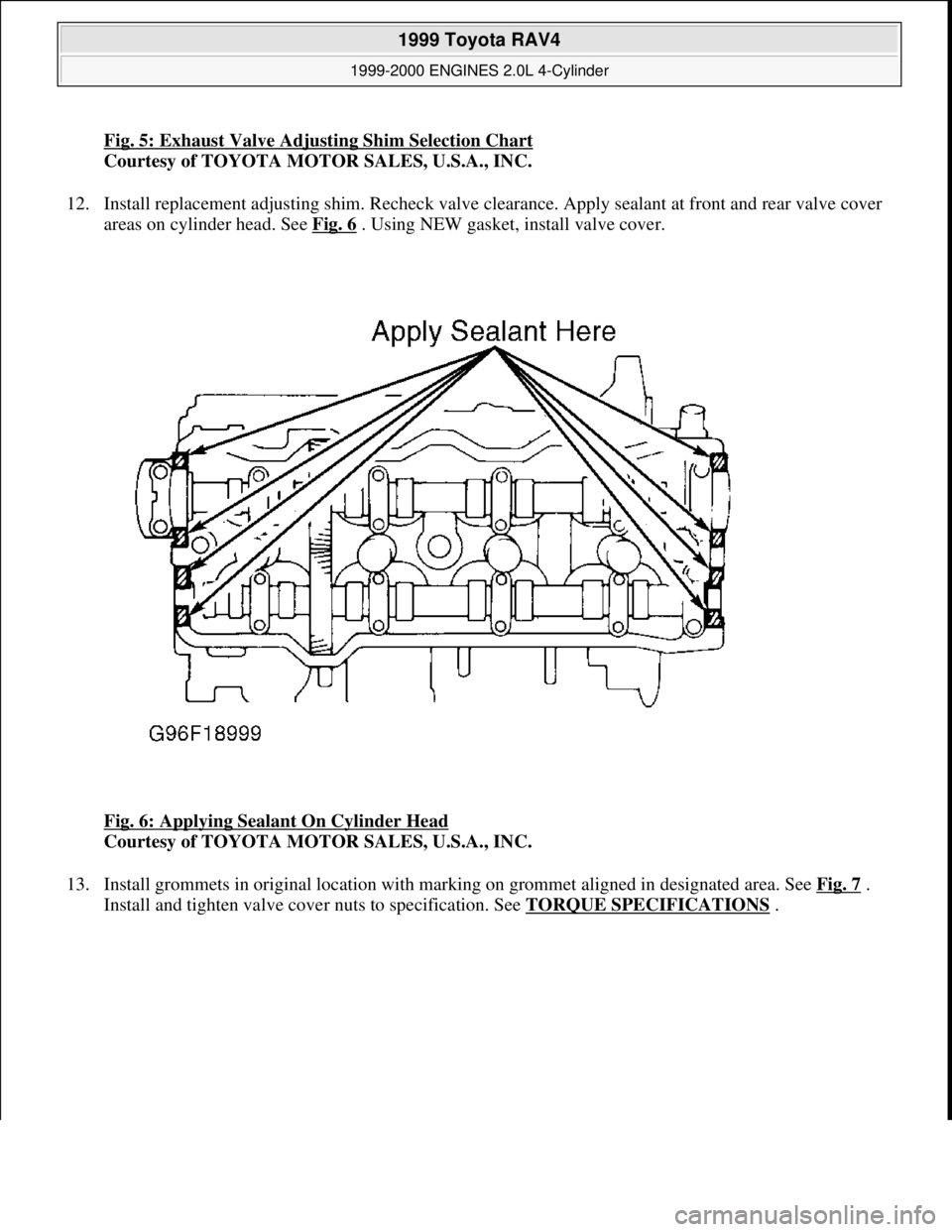
Fig. 5: Exhaust Valve Adjusting Shim Selection Chart
Courtesy of TOYOTA MOTOR SALES, U.S.A., INC.
12. Install replacement adjusting shim. Recheck valve clearance. Apply sealant at front and rear valve cover
areas on cylinder head. See Fig. 6
. Using NEW gasket, install valve cover.
Fig. 6: Applying Sealant On Cylinder Head
Courtesy of TOYOTA MOTOR SALES, U.S.A., INC.
13. Install grommets in original location with marking on grommet aligned in designated area. See Fig. 7
.
Install and ti
ghten valve cover nuts to specification. See TORQUE SPECIFICATIONS.
1999 Toyota RAV4
1999-2000 ENGINES 2.0L 4-Cylinder
Microsoft
Sunday, November 22, 2009 10:22:26 AMPage 8 © 2005 Mitchell Repair Information Company, LLC.
Page 692 of 1632
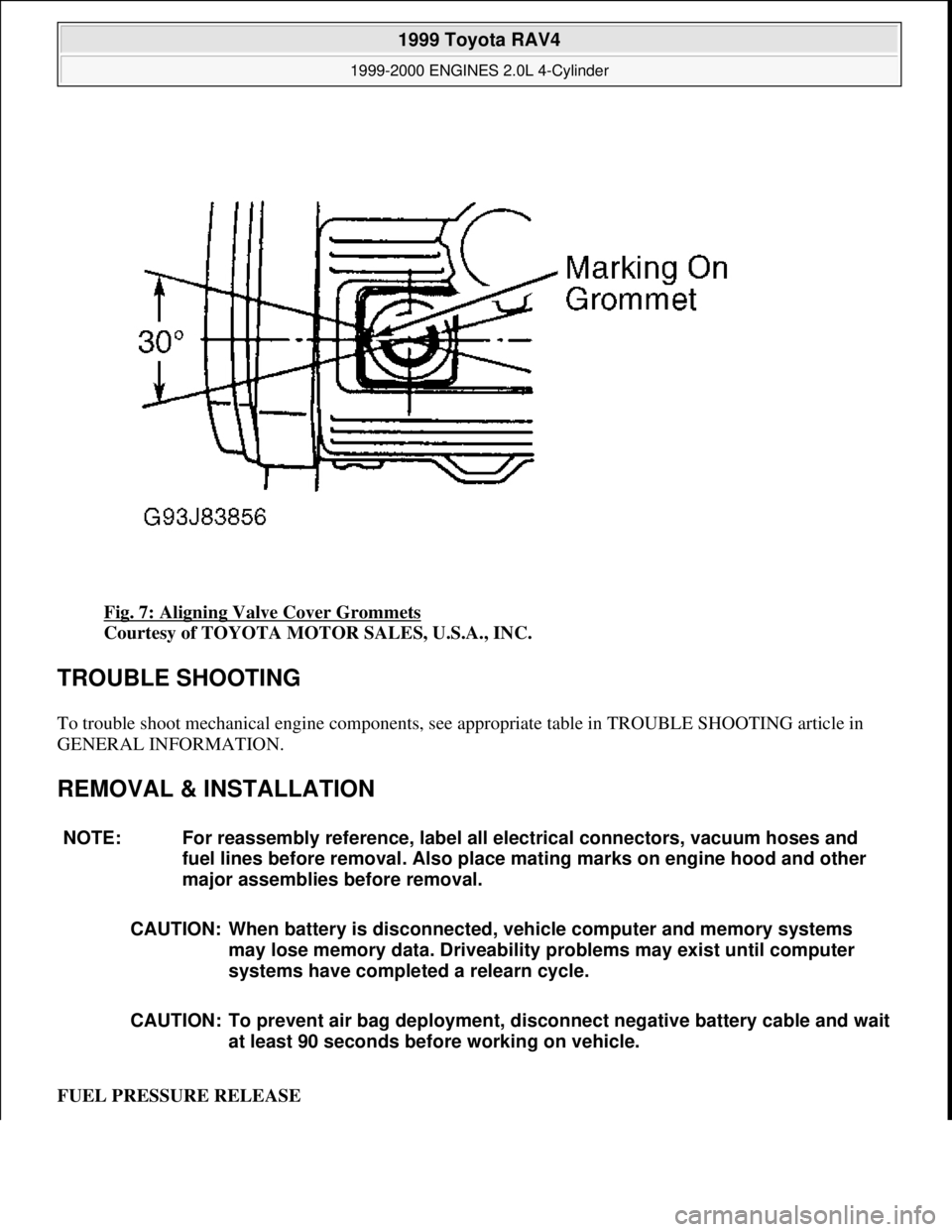
Fig. 7: Aligning Valve Cover Grommets
Courtesy of TOYOTA MOTOR SALES, U.S.A., INC.
TROUBLE SHOOTING
To trouble shoot mechanical engine components, see appropriate table in TROUBLE SHOOTING article in
GENERAL INFORMATION.
REMOVAL & INSTALLATION
FUEL PRESSURE RELEASE
NOTE: For reassembly reference, label all electrical connectors, vacuum hoses and
fuel lines before removal. Also place mating marks on engine hood and other
major assemblies before removal.
CAUTION: When battery is disconnected, vehicle computer and memory systems
may lose memory data. Driveability problems may exist until computer
systems have completed a relearn cycle.
CAUTION: To prevent air bag deployment, disconnect negative battery cable and wait
at least 90 seconds before working on vehicle.
1999 Toyota RAV4
1999-2000 ENGINES 2.0L 4-Cylinder
Microsoft
Sunday, November 22, 2009 10:22:26 AMPage 9 © 2005 Mitchell Repair Information Company, LLC.
Page 693 of 1632
1. Remove driver-side rear seat and floor panel cover for access to fuel pump electrical connector.
2. Disconnect fuel pump electrical connector. Start engine and allow engine to idle until engine stalls. Turn
ignition off.
3. Reconnect fuel pump electrical connector. Reinstall floor panel cover and driver-side rear seat.
4. Disconnect negative battery cable. Place an approved gasoline container under fuel line. Cover fuel line
connection with shop towel.
5. Slowly loosen fuel line connection to release fuel pressure. Once fuel pressure is released, fuel system
components may be serviced.
ENGINE
Removal
1. Engine and transaxle are removed as an assembly from bottom of engine compartment. Release fuel
pressure. See FUEL PRESSURE RELEASE
. Remove hood, battery and battery tray. Drain cooling
system, and engine and transaxle oil.
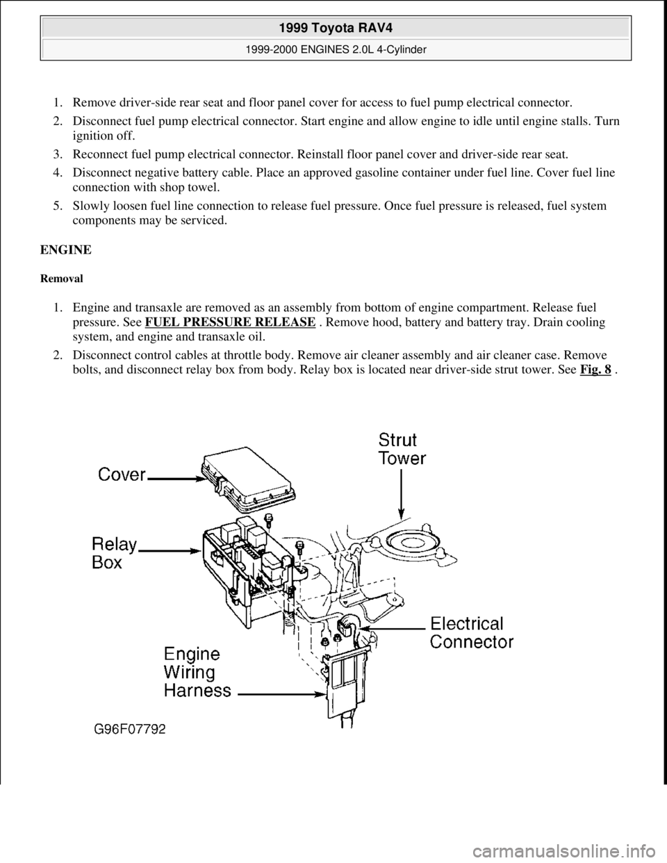
2. Disconnect control cables at throttle body. Remove air cleaner assembly and air cleaner case. Remove
bolts, and disconnect relay box from body. Relay box is located near driver-side strut tower. See Fig. 8
.
1999 Toyota RAV4
1999-2000 ENGINES 2.0L 4-Cylinder
Microsoft
Sunday, November 22, 2009 10:22:26 AMPage 10 © 2005 Mitchell Repair Information Company, LLC.
Page 694 of 1632
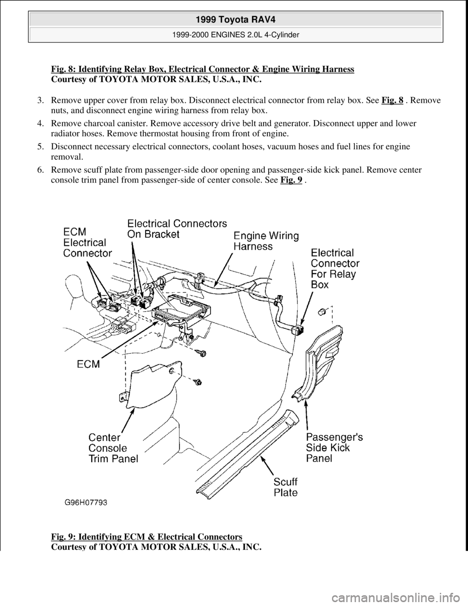
Fig. 8: Identifying Relay Box, Electrical Connector & Engine Wiring Harness
Courtesy of TOYOTA MOTOR SALES, U.S.A., INC.
3. Remove upper cover from relay box. Disconnect electrical connector from relay box. See Fig. 8
. Remove
nuts, and disconnect engine wiring harness from relay box.
4. Remove charcoal canister. Remove accessory drive belt and generator. Disconnect upper and lower
radiator hoses. Remove thermostat housing from front of engine.
5. Disconnect necessary electrical connectors, coolant hoses, vacuum hoses and fuel lines for engine
removal.
6. Remove scuff plate from passenger-side door opening and passenger-side kick panel. Remove center
console trim panel from passenger-side of center console. See Fig. 9
.
Fig. 9: Identifying ECM & Electrical Connectors
Courtesy of TOYOTA MOTOR SALES, U.S.A., INC.
1999 Toyota RAV4
1999-2000 ENGINES 2.0L 4-Cylinder
Microsoft
Sunday, November 22, 2009 10:22:26 AMPage 11 © 2005 Mitchell Repair Information Company, LLC.
Page 695 of 1632
7. Disconnect 2 electrical connectors from Engine Control Module (ECM) and 2 electrical connectors on
bracket. See Fig. 9
. Disconnect electrical connector for relay box located behind passenger-side kick
panel.
8. Disconnect engine wiring harness clamp located on engine wiring harness, near firewall. Pull engine
wiring harness out through firewall.
9. Raise and support vehicle. Remove lower engine covers. On M/T models, remove clutch release cylinder
with hose attached, and secure aside. Disconnect transaxle control cables from transaxle. Remove starter
and transaxle ground cable. On A/T, and 4WD vehicles with M/T, disconnect transaxle oil cooler hoses.
10. On A/T models, disconnect transaxle control cable from front suspension crossmember and engine mount
center member. Disconnect connectors, plug wires, strap and hoses from top of engine. On 4WD M/T,
disconnect ground strap from engine cowl. Disconnect differential lock control solenoid connector.
11. Using 14-mm deep socket wrench, remove 2 bolts holding front exhaust pipe to front TWC. Remove 2
bolts and 2 nuts holding front exhaust pipe to TWC. Remove front exhaust pipe and 2 gaskets.
12. Disconnect A/C compressor connector. Remove 2 bolts, nut and stud bolt. Disconnect A/C compressor
from engine, and secure aside. On 4WD vehicles, remove rear drive shaft. On all models, remove front
drive shaft.
13. Remove front wheel and engine undercover. On M/T vehicles drain gear oil. On A/T models, drain
transmission fluid. On vehicles with ABS, remove bolt and ABS speed sensor. Remove cotter pin, lock
cap and lock nut.
14. Disconnect tie rod from steering knuckle. Disconnect stabilizer bar link from lower control arm.
Disconnect lower ball joint from lower control arm.
15. Using soft-face hammer, tap axle shaft from hub assembly. Pull steering knuckle outward and separate
axle shaft from hub assembly.
16. On 2WD A/T models, remove axle shaft bearing bracket bolts for right (passenger-side) axle shaft. See
Fig. 10
. Remove right axle shaft assembly from transaxle and axle shaft bearing bracket.
1999 Toyota RAV4
1999-2000 ENGINES 2.0L 4-Cylinder
Microsoft
Sunday, November 22, 2009 10:22:26 AMPage 12 © 2005 Mitchell Repair Information Company, LLC.
Page 696 of 1632
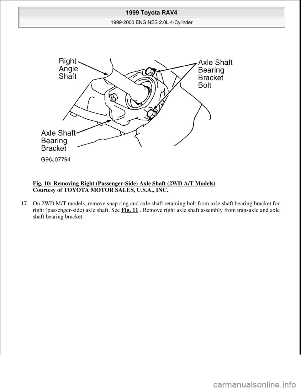
Fig. 10: Removing Right (Passenger-Side) Axle Shaft (2WD A/T Models)
Courtesy of TOYOTA MOTOR SALES, U.S.A., INC.
17. On 2WD M/T models, remove snap ring and axle shaft retaining bolt from axle shaft bearing bracket for
right (passenger-side) axle shaft. See Fig. 11
. Remove right axle shaft assembly from transaxle and axle
shaft bearin
g bracket.
1999 Toyota RAV4
1999-2000 ENGINES 2.0L 4-Cylinder
Microsoft
Sunday, November 22, 2009 10:22:26 AMPage 13 © 2005 Mitchell Repair Information Company, LLC.
Page 697 of 1632
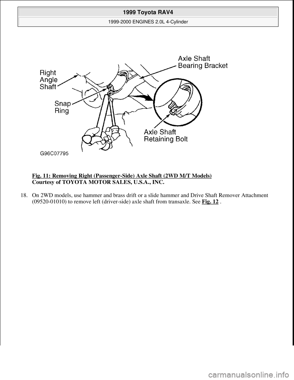
Fig. 11: Removing Right (Passenger-Side) Axle Shaft (2WD M/T Models)
Courtesy of TOYOTA MOTOR SALES, U.S.A., INC.
18. On 2WD models, use hammer and brass drift or a slide hammer and Drive Shaft Remover Attachment
(09520-01010) to remove left (drive
r-side) axle shaft from transaxle. See Fig. 12 .
1999 Toyota RAV4
1999-2000 ENGINES 2.0L 4-Cylinder
Microsoft
Sunday, November 22, 2009 10:22:26 AMPage 14 © 2005 Mitchell Repair Information Company, LLC.
Page 698 of 1632
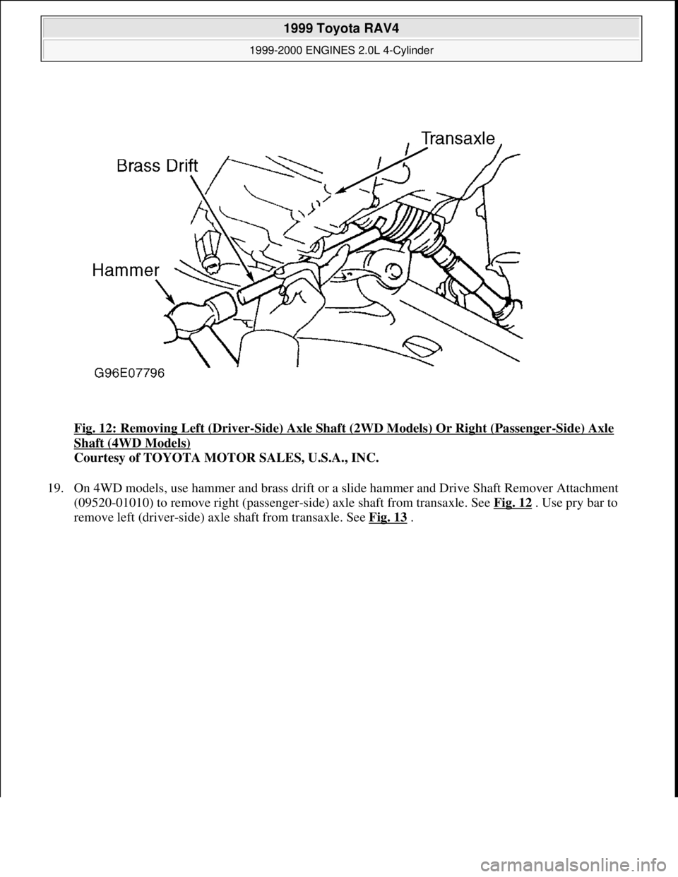
Fig. 12: Removing Left (Driver-Side) Axle Shaft (2WD Models) Or Right (Passenger-Side) Axle
Shaft (4WD Models)
Courtesy of TOYOTA MOTOR SALES, U.S.A., INC.
19. On 4WD models, use hammer and brass drift or a slide hammer and Drive Shaft Remover Attachment
(09520-01010) to remove right (passenger-side) axle shaft from transaxle. See Fig. 12
. Use pry bar to
remove left (drive
r-side) axle shaft from transaxle. See Fig. 13.
1999 Toyota RAV4
1999-2000 ENGINES 2.0L 4-Cylinder
Microsoft
Sunday, November 22, 2009 10:22:26 AMPage 15 © 2005 Mitchell Repair Information Company, LLC.
Page 699 of 1632
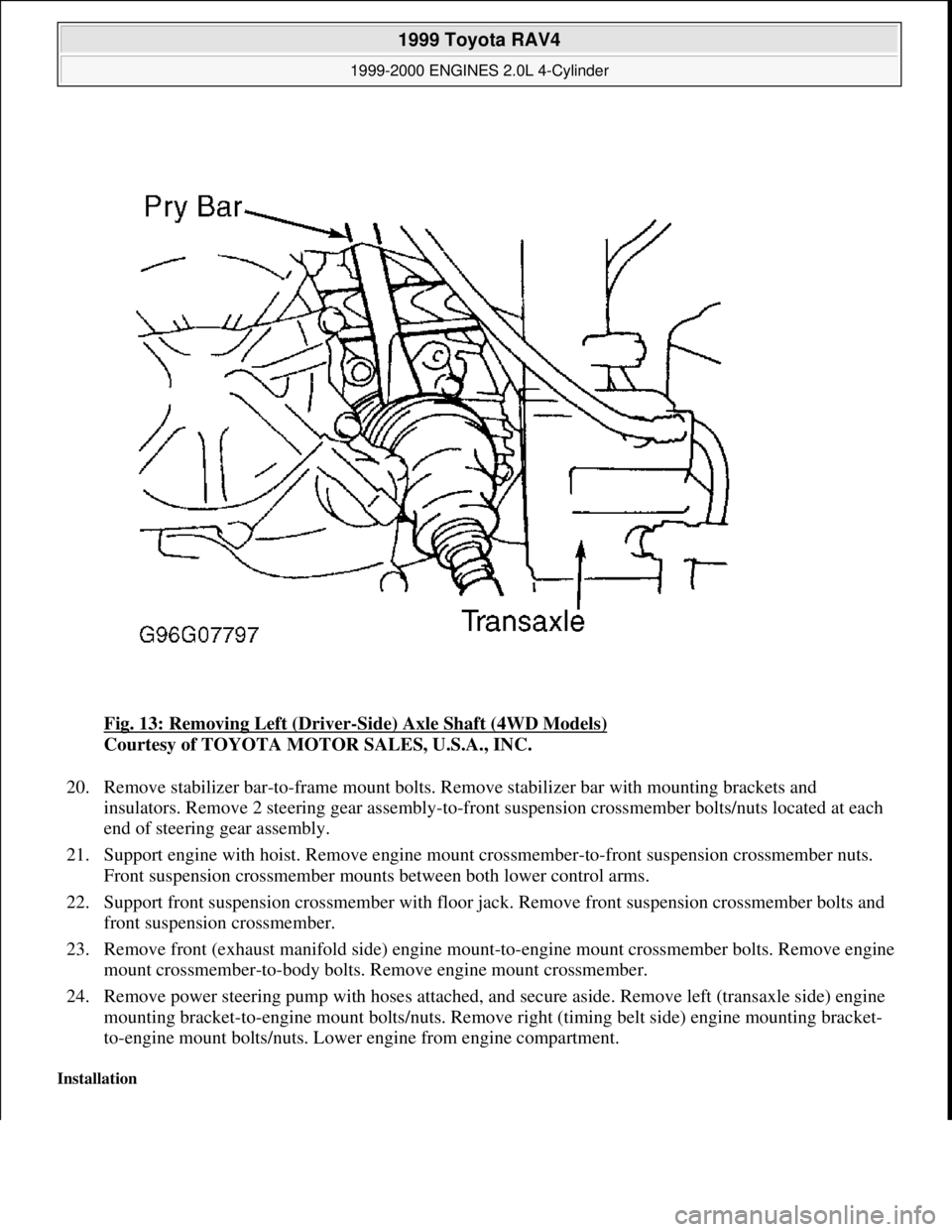
Fig. 13: Removing Left (Driver-Side) Axle Shaft (4WD Models)
Courtesy of TOYOTA MOTOR SALES, U.S.A., INC.
20. Remove stabilizer bar-to-frame mount bolts. Remove stabilizer bar with mounting brackets and
insulators. Remove 2 steering gear assembly-to-front suspension crossmember bolts/nuts located at each
end of steering gear assembly.
21. Support engine with hoist. Remove engine mount crossmember-to-front suspension crossmember nuts.
Front suspension crossmember mounts between both lower control arms.
22. Support front suspension crossmember with floor jack. Remove front suspension crossmember bolts and
front suspension crossmember.
23. Remove front (exhaust manifold side) engine mount-to-engine mount crossmember bolts. Remove engine
mount crossmember-to-body bolts. Remove engine mount crossmember.
24. Remove power steering pump with hoses attached, and secure aside. Remove left (transaxle side) engine
mounting bracket-to-engine mount bolts/nuts. Remove right (timing belt side) engine mounting bracket-
to-engine mount bolts/nuts. Lower engine from engine compartment.
Installation
1999 Toyota RAV4
1999-2000 ENGINES 2.0L 4-Cylinder
Microsoft
Sunday, November 22, 2009 10:22:26 AMPage 16 © 2005 Mitchell Repair Information Company, LLC.
Page 700 of 1632
1. Install engine in engine compartment. Loosely install right (timing belt side) engine mounting bracket-to-
engine mount bolts/nuts.
2. Install and tighten left (transaxle side) engine mounting bracket-to-engine mount bolts/nuts to
specification. See TORQUE SPECIFICATIONS
. Tighten right (timing belt side) engine mounting
bracket-to-engine mount bolts/nuts to specification.
3. Install power steering pump. Install and tighten bolts to specification. See TORQUE
SPECIFICATIONS . Install engine mount crossmember with front (exhaust manifold side) engine
mount-to-engine mount crossmember bolts and engine mount crossmember-to-body bolts loosely
installed. DO NOT tighten bolts at this time
4. Install front suspension crossmember on body with bolts loosely installed. Loosely install engine mount
crossmember-to-front suspension crossmember nuts and steering gear assembly-to-front suspension
crossmember bolts/nuts. DO NOT tighten bolts/nuts at this time.
5. Install and tighten front suspension crossmember bolts to specification. See TORQUE
SPECIFICATIONS .
6. Tighten steering gear assembly-to-front suspension crossmember bolts/nuts and then engine mount
crossmember-to-front suspension crossmember nuts to specification. See TORQUE
SPECIFICATIONS .
7. Tighten front (exhaust manifold side) engine mount-to-engine mount crossmember bolts and then engine
mount crossmember-to-body bolts to specification. See TORQUE SPECIFICATIONS
.
8. To install remaining components, reverse removal procedure. Before installing axle shafts coat axle shaft
seals in transaxle with grease.
9. On all axle shafts except right (passenger-side) axle shaft on 2WD models, install NEW snap ring on end
of axle shaft. Position snap ring on end of axle shaft with opening facing downward.
10. Install axle shaft by lightly tapping axle shaft into transaxle. Ensure axle shaft moves inward and outward
approximately .079-.120" (2.00-3.00 mm) and cannot be pulled from transaxle.
11. On 2WD M/T models, when installing right (passenger-side) axle shaft, install NEW axle shaft retaining
bolt. Tighten axle shaft retaining bolt to specification. See TORQUE SPECIFICATIONS
.
12. On 4WD models, ensure reference marks on drive shaft flanges are aligned. Ensure mounting bracket on
drive shaft center support bearing is straight and perpendicular to drive shaft before tightening bolts to
specification.
13. Use NEW gasket and NEW nuts when installing front exhaust pipe on catalytic converter. Ensure all
bolts/nuts are loosely installed before tightening to specification.
14. Adjust fluid levels and control cables. On 2WD models with A/T, use Dexron-II ATF. On 4WD models
with A/T, use Type "T" ATF. On all M/T models, use SAE 75-90 GL-5 gear oil.
CYLINDER HEAD & MANIFOLDS NOTE: All axle shafts, except right (passenger-side) axle shaft on 2WD models,
use a snap ring on end of axle shaft. Ensure NEW snap ring is installed.
NOTE: On 4WD models, manufacturer recommends engine removal for servicing of
cylinder head and manifolds. See ENGINE
.
1999 Toyota RAV4
1999-2000 ENGINES 2.0L 4-Cylinder
Microsoft
Sunday, November 22, 2009 10:22:26 AMPage 17 © 2005 Mitchell Repair Information Company, LLC.