TOYOTA RAV4 1996 Service Repair Manual
Manufacturer: TOYOTA, Model Year: 1996, Model line: RAV4, Model: TOYOTA RAV4 1996Pages: 1632, PDF Size: 41.64 MB
Page 671 of 1632
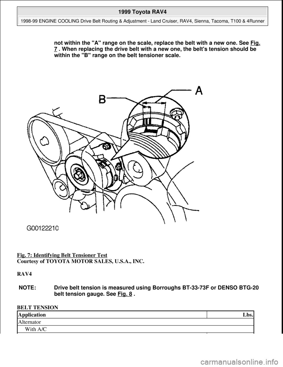
Fig. 7: Identifying Belt Tensioner Test
Courtesy of TOYOTA MOTOR SALES, U.S.A., INC.
RAV4
BELT TENSION not within the "A" range on the scale, replace the belt with a new one. See Fig.
7 . When replacing the drive belt with a new one, the belt's tension should be
within the "B" range on the belt tensioner scale.
NOTE: Drive belt tension is measured using Borroughs BT-33-73F or DENSO BTG-20
belt tension gauge. See Fig. 8
.
ApplicationLbs.
Alternator
With A/C
1999 Toyota RAV4
1998-99 ENGINE COOLING Drive Belt Routing & Adjustment - Land Cruiser, RAV4, Sienna, Tacoma, T100 & 4Runner
Microsoft
Sunday, November 22, 2009 10:20:43 AMPage 7 © 2005 Mitchell Repair Information Company, LLC.
Page 672 of 1632
SIENNA
BELT TENSION
TACOMA (1998)
BELT TENSION
New140-190
Used100-120
Without A/C
New100-150
Used75-115
A/C Compressor
New135-185
Used80-120
Power Steering
New95-145
Used60-100
NOTE: Drive belt tension is measured using Borroughs BT-33-73F or DENSO BTG-20
belt tension gauge. See Fig. 8
.
ApplicationLbs.
Alternator
New170-180
Used95-135
A/C Compressor
New139-191
Used66-110
Power Steering
New150-185
Used95-135
NOTE: Drive belt tension is measured using Borroughs BT-33-73F or DENSO BTG-20
belt tension gauge. See Fig. 8
.
ApplicationLbs.
Alternator
2RZ-FE & 3RZ-FE Engine
New116-169
Used66-88
5VZ-FE Engine
1999 Toyota RAV4
1998-99 ENGINE COOLING Drive Belt Routing & Adjustment - Land Cruiser, RAV4, Sienna, Tacoma, T100 & 4Runner
Microsoft
Sunday, November 22, 2009 10:20:43 AMPage 8 © 2005 Mitchell Repair Information Company, LLC.
Page 673 of 1632
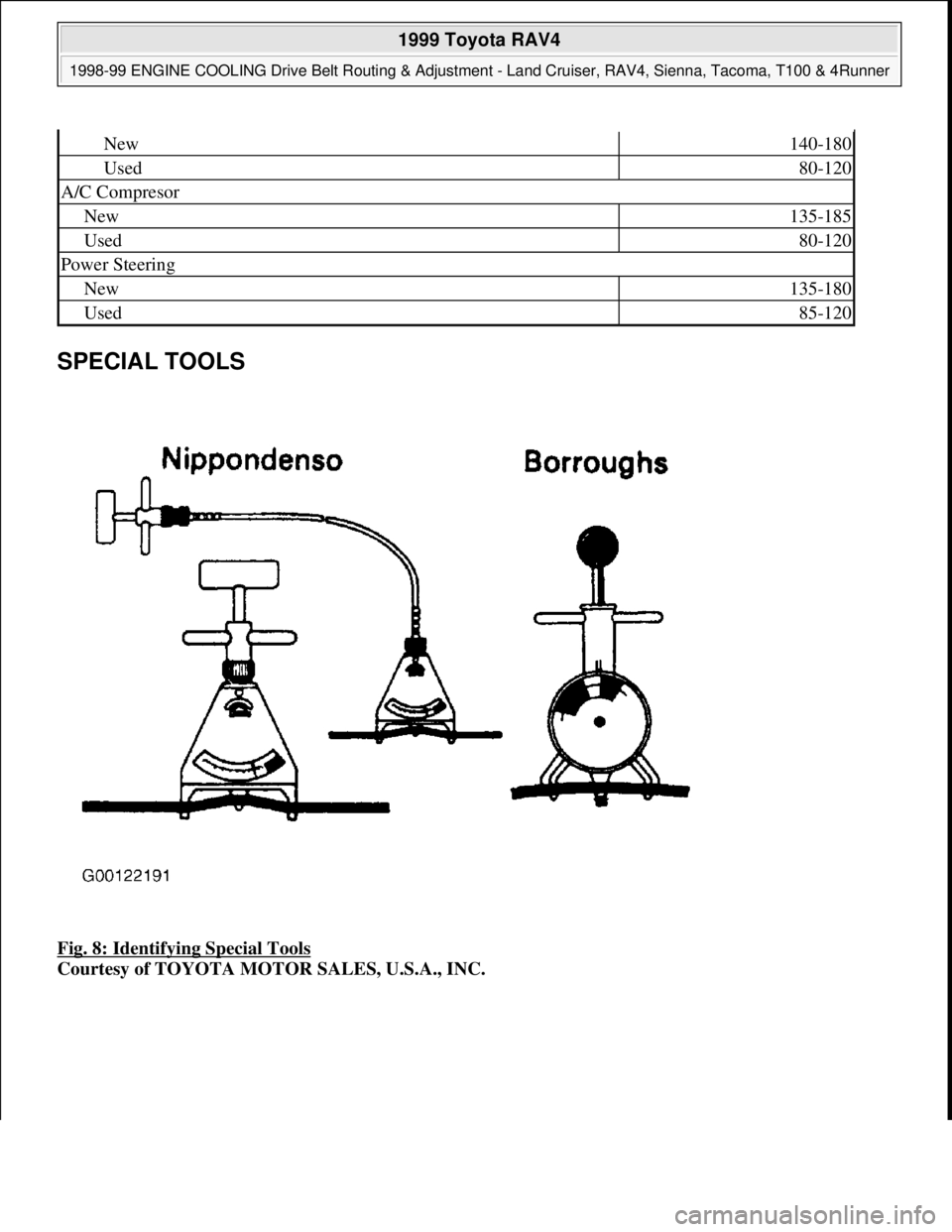
SPECIAL TOOLS
Fig. 8: Identifying Special Tools
Courtesy of TOYOTA MOTOR SALES, U.S.A., INC.
New140-180
Used80-120
A/C Compresor
New135-185
Used80-120
Power Steering
New135-180
Used85-120
1999 Toyota RAV4
1998-99 ENGINE COOLING Drive Belt Routing & Adjustment - Land Cruiser, RAV4, Sienna, Tacoma, T100 & 4Runner
Microsoft
Sunday, November 22, 2009 10:20:43 AMPage 9 © 2005 Mitchell Repair Information Company, LLC.
Page 674 of 1632
1999 TOYOTA
RAV4
BUZZERS, RELAYS & TIMERS
BUZZERS, RELAYS & TIMERS
CIRCUIT PROTECTION DEVICES
CIRCUIT PROTECTION DEVICES
ComponentComponent Location
ABS RelayOn left front of engine compartment, behind radiator. See Fig. 1 .
ACC RelayOn instrument panel J/B.
Circuit Opening RelayOn driver side R/B.
Daytime Running Light Relay (Main)Behind right side of dash. See Fig. 4 .
Daytime Running Light Relay No. 3On passenger side R/B.
Daytime Running Light Relay No. 4On passenger side R/B.
DIM RelayOn engine room R/B No. 2.
EFI RelayOn instrument panel J/B.
E/G MAIN RelayOn engine room R/B.
FAN No. 1 RelayOn engine room R/B No. 2.
FAN No. 2 RelayOn engine room R/B No. 2.
FAN No. 3 RelayOn engine room R/B No. 2.
H-LP RelayOn engine room R/B.
Heater RelayOn passenger side R/B.
IG1 RelayOn instrument panel J/B.
IG2 RelayOn engine room R/B No. 2.
Integration RelayOn instrument panel J/B. See Fig. 4 .
MG/C RelayOn engine room R/B No. 2.
Moon Roof Control RelayOn roof, in front of moon roof.
Power RelayOn instrument panel J/B.
ST RelayOn engine room R/B.
Taillight RelayOn driver side R/B.
Turn Signal FlasherOn driver side R/B.
ComponentComponent Location
Driver Side R/BAt left kick panel. See Fig. 4 .
Engine Room R/BOn left front strut tower. See Fig. 1 .
Engine Room R/B No. 2In front of left front strut tower. See Fig. 1 .
Fusible Link BlockOn right side of engine compartment, near battery. See Fig. 1 .
Instrument Panel J/BOn lower left side of dash. See Fig. 4 .
1999 Toyota RAV4
1999 TOYOTA RAV4
1999 Toyota RAV4
1999 TOYOTA RAV4
Microsoft
Sunday, November 22, 2009 10:17:32 AMPage 1 © 2005 Mitchell Repair Information Company, LLC.
Microsoft
Sunday, November 22, 2009 10:17:35 AMPage 1 © 2005 Mitchell Repair Information Company, LLC.
Page 675 of 1632
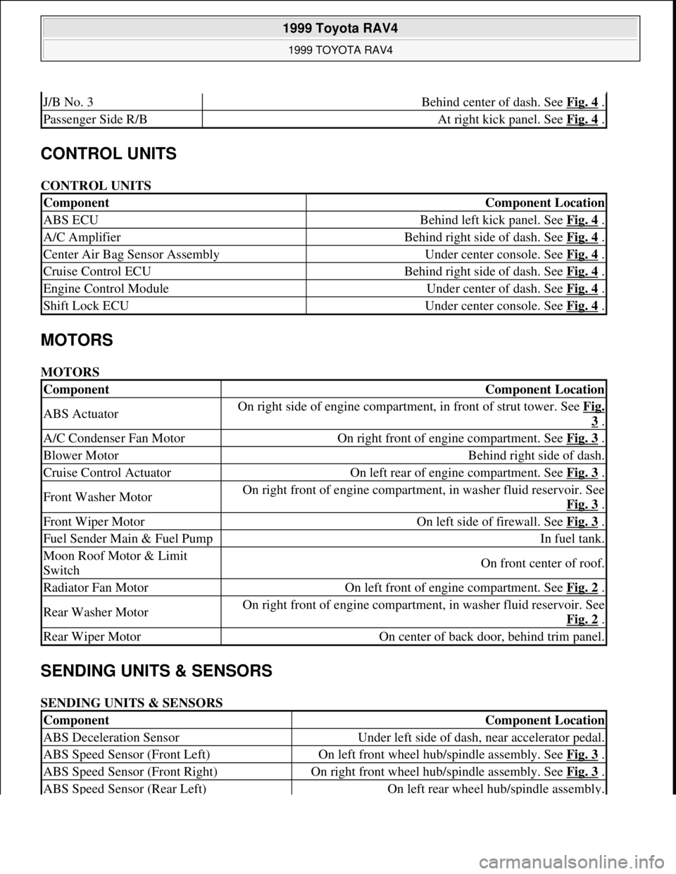
CONTROL UNITS
CONTROL UNITS
MOTORS
MOTORS
SENDING UNITS & SENSORS
SENDING UNITS & SENSORS
J/B No. 3Behind center of dash. See Fig. 4 .
Passenger Side R/BAt right kick panel. See Fig. 4 .
ComponentComponent Location
ABS ECUBehind left kick panel. See Fig. 4 .
A/C AmplifierBehind right side of dash. See Fig. 4 .
Center Air Bag Sensor AssemblyUnder center console. See Fig. 4 .
Cruise Control ECUBehind right side of dash. See Fig. 4 .
Engine Control ModuleUnder center of dash. See Fig. 4 .
Shift Lock ECUUnder center console. See Fig. 4 .
ComponentComponent Location
ABS ActuatorOn right side of engine compartment, in front of strut tower. See Fig.
3 .
A/C Condenser Fan MotorOn right front of engine compartment. See Fig. 3 .
Blower MotorBehind right side of dash.
Cruise Control ActuatorOn left rear of engine compartment. See Fig. 3 .
Front Washer MotorOn right front of engine compartment, in washer fluid reservoir. See
Fig. 3
.
Front Wiper MotorOn left side of firewall. See Fig. 3 .
Fuel Sender Main & Fuel PumpIn fuel tank.
Moon Roof Motor & Limit
SwitchOn front center of roof.
Radiator Fan MotorOn left front of engine compartment. See Fig. 2 .
Rear Washer MotorOn right front of engine compartment, in washer fluid reservoir. See
Fig. 2
.
Rear Wiper MotorOn center of back door, behind trim panel.
ComponentComponent Location
ABS Deceleration SensorUnder left side of dash, near accelerator pedal.
ABS Speed Sensor (Front Left)On left front wheel hub/spindle assembly. See Fig. 3 .
ABS Speed Sensor (Front Right)On right front wheel hub/spindle assembly. See Fig. 3 .
ABS Speed Sensor (Rear Left)On left rear wheel hub/spindle assembly.
1999 Toyota RAV4
1999 TOYOTA RAV4
Microsoft
Sunday, November 22, 2009 10:17:32 AMPage 2 © 2005 Mitchell Repair Information Company, LLC.
Page 676 of 1632
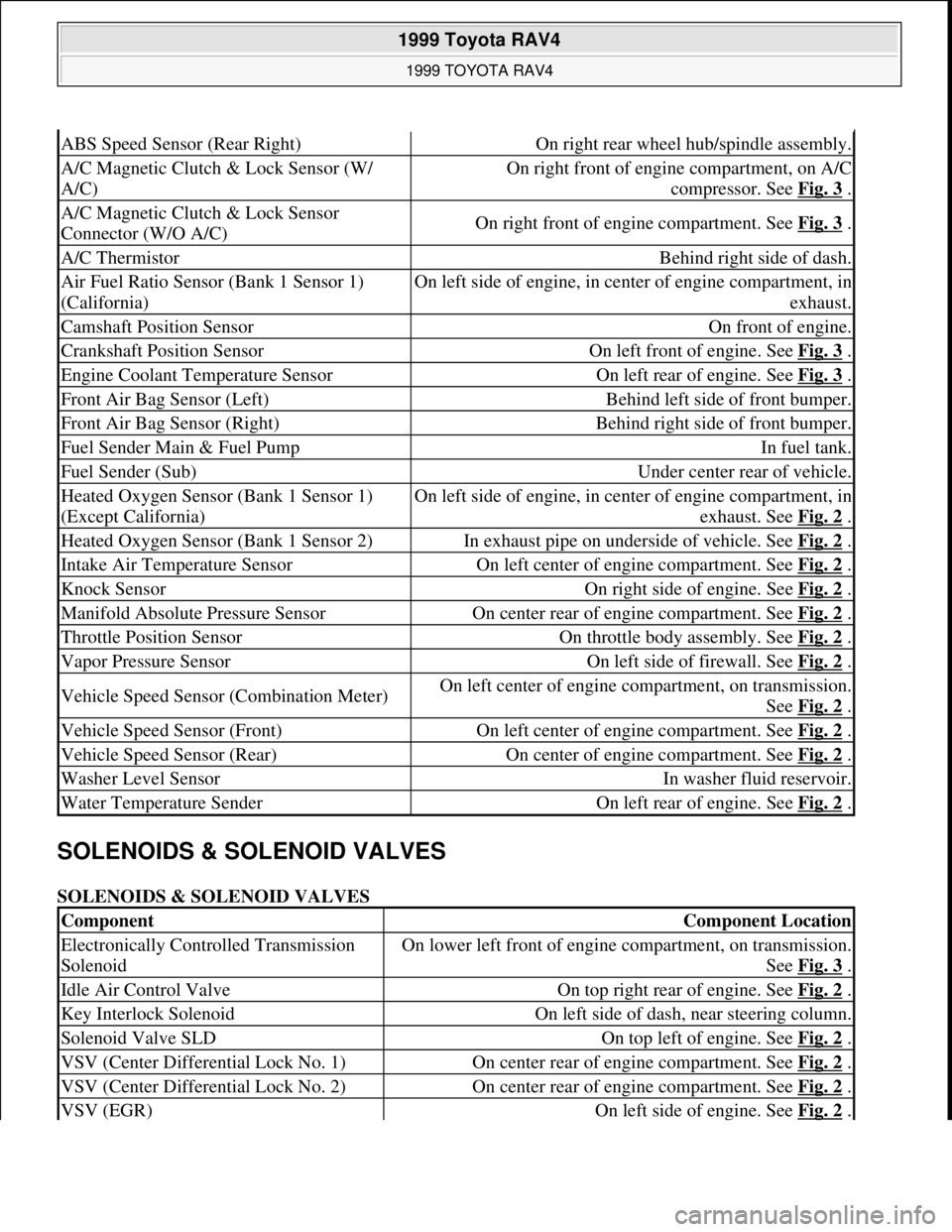
SOLENOIDS & SOLENOID VALVES
SOLENOIDS & SOLENOID VALVES
ABS Speed Sensor (Rear Right)On right rear wheel hub/spindle assembly.
A/C Magnetic Clutch & Lock Sensor (W/
A/C)On right front of engine compartment, on A/C
compressor. See Fig. 3
.
A/C Magnetic Clutch & Lock Sensor
Connector (W/O A/C)On right front of engine compartment. See Fig. 3 .
A/C ThermistorBehind right side of dash.
Air Fuel Ratio Sensor (Bank 1 Sensor 1)
(California)On left side of engine, in center of engine compartment, in
exhaust.
Camshaft Position SensorOn front of engine.
Crankshaft Position SensorOn left front of engine. See Fig. 3 .
Engine Coolant Temperature SensorOn left rear of engine. See Fig. 3 .
Front Air Bag Sensor (Left)Behind left side of front bumper.
Front Air Bag Sensor (Right)Behind right side of front bumper.
Fuel Sender Main & Fuel PumpIn fuel tank.
Fuel Sender (Sub)Under center rear of vehicle.
Heated Oxygen Sensor (Bank 1 Sensor 1)
(Except California)On left side of engine, in center of engine compartment, in
exhaust. See Fig. 2
.
Heated Oxygen Sensor (Bank 1 Sensor 2)In exhaust pipe on underside of vehicle. See Fig. 2 .
Intake Air Temperature SensorOn left center of engine compartment. See Fig. 2 .
Knock SensorOn right side of engine. See Fig. 2 .
Manifold Absolute Pressure SensorOn center rear of engine compartment. See Fig. 2 .
Throttle Position SensorOn throttle body assembly. See Fig. 2 .
Vapor Pressure SensorOn left side of firewall. See Fig. 2 .
Vehicle Speed Sensor (Combination Meter)On left center of engine compartment, on transmission.
See Fig. 2
.
Vehicle Speed Sensor (Front)On left center of engine compartment. See Fig. 2 .
Vehicle Speed Sensor (Rear)On center of engine compartment. See Fig. 2 .
Washer Level SensorIn washer fluid reservoir.
Water Temperature SenderOn left rear of engine. See Fig. 2 .
ComponentComponent Location
Electronically Controlled Transmission
SolenoidOn lower left front of engine compartment, on transmission.
See Fig. 3
.
Idle Air Control ValveOn top right rear of engine. See Fig. 2 .
Key Interlock SolenoidOn left side of dash, near steering column.
Solenoid Valve SLDOn top left of engine. See Fig. 2 .
VSV (Center Differential Lock No. 1)On center rear of engine compartment. See Fig. 2 .
VSV (Center Differential Lock No. 2)On center rear of engine compartment. See Fig. 2 .
VSV (EGR)On left side of engine. See Fig. 2 .
1999 Toyota RAV4
1999 TOYOTA RAV4
Microsoft
Sunday, November 22, 2009 10:17:32 AMPage 3 © 2005 Mitchell Repair Information Company, LLC.
Page 677 of 1632
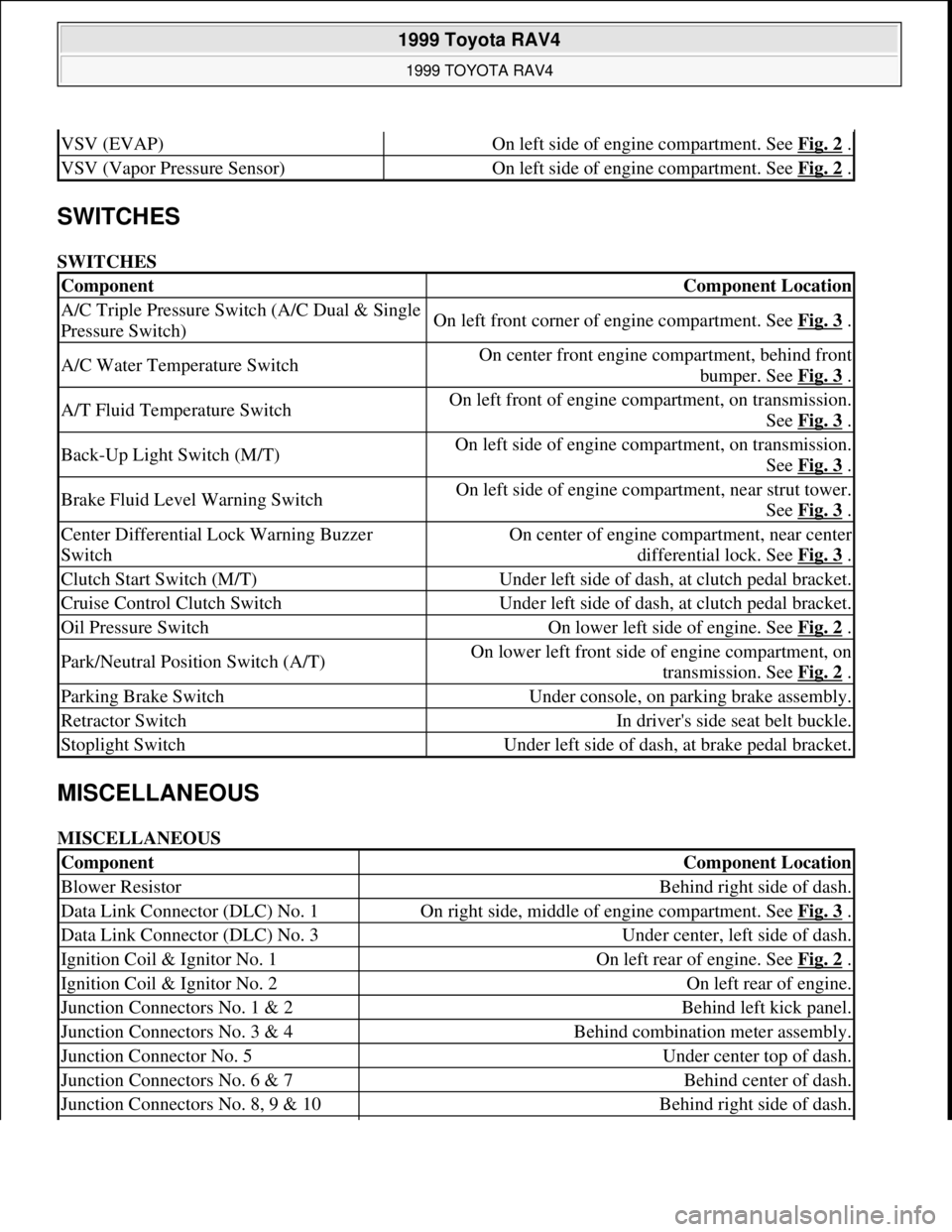
SWITCHES
SWITCHES
MISCELLANEOUS
MISCELLANEOUS
VSV (EVAP)On left side of engine compartment. See Fig. 2 .
VSV (Vapor Pressure Sensor)On left side of engine compartment. See Fig. 2 .
ComponentComponent Location
A/C Triple Pressure Switch (A/C Dual & Single
Pressure Switch)On left front corner of engine compartment. See Fig. 3 .
A/C Water Temperature SwitchOn center front engine compartment, behind front
bumper. See Fig. 3
.
A/T Fluid Temperature SwitchOn left front of engine compartment, on transmission.
See Fig. 3
.
Back-Up Light Switch (M/T)On left side of engine compartment, on transmission.
See Fig. 3
.
Brake Fluid Level Warning SwitchOn left side of engine compartment, near strut tower.
See Fig. 3
.
Center Differential Lock Warning Buzzer
SwitchOn center of engine compartment, near center
differential lock. See Fig. 3
.
Clutch Start Switch (M/T)Under left side of dash, at clutch pedal bracket.
Cruise Control Clutch SwitchUnder left side of dash, at clutch pedal bracket.
Oil Pressure SwitchOn lower left side of engine. See Fig. 2 .
Park/Neutral Position Switch (A/T)On lower left front side of engine compartment, on
transmission. See Fig. 2
.
Parking Brake SwitchUnder console, on parking brake assembly.
Retractor SwitchIn driver's side seat belt buckle.
Stoplight SwitchUnder left side of dash, at brake pedal bracket.
ComponentComponent Location
Blower ResistorBehind right side of dash.
Data Link Connector (DLC) No. 1On right side, middle of engine compartment. See Fig. 3 .
Data Link Connector (DLC) No. 3Under center, left side of dash.
Ignition Coil & Ignitor No. 1On left rear of engine. See Fig. 2 .
Ignition Coil & Ignitor No. 2On left rear of engine.
Junction Connectors No. 1 & 2Behind left kick panel.
Junction Connectors No. 3 & 4Behind combination meter assembly.
Junction Connector No. 5Under center top of dash.
Junction Connectors No. 6 & 7Behind center of dash.
Junction Connectors No. 8, 9 & 10Behind right side of dash.
1999 Toyota RAV4
1999 TOYOTA RAV4
Microsoft
Sunday, November 22, 2009 10:17:32 AMPage 4 © 2005 Mitchell Repair Information Company, LLC.
Page 678 of 1632
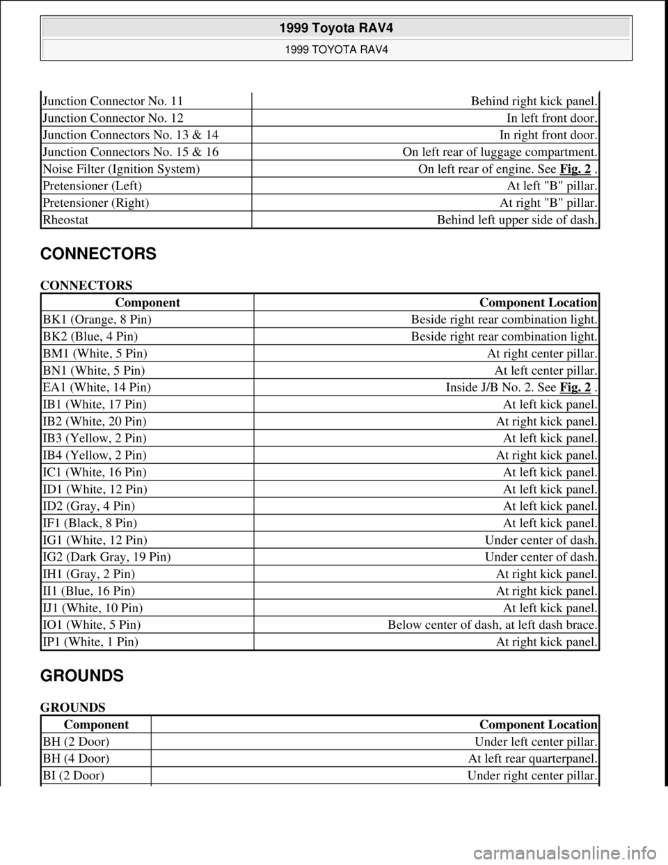
CONNECTORS
CONNECTORS
GROUNDS
GROUNDS
Junction Connector No. 11Behind right kick panel.
Junction Connector No. 12In left front door.
Junction Connectors No. 13 & 14In right front door.
Junction Connectors No. 15 & 16On left rear of luggage compartment.
Noise Filter (Ignition System)On left rear of engine. See Fig. 2 .
Pretensioner (Left)At left "B" pillar.
Pretensioner (Right)At right "B" pillar.
RheostatBehind left upper side of dash.
ComponentComponent Location
BK1 (Orange, 8 Pin)Beside right rear combination light.
BK2 (Blue, 4 Pin)Beside right rear combination light.
BM1 (White, 5 Pin)At right center pillar.
BN1 (White, 5 Pin)At left center pillar.
EA1 (White, 14 Pin)Inside J/B No. 2. See Fig. 2 .
IB1 (White, 17 Pin)At left kick panel.
IB2 (White, 20 Pin)At right kick panel.
IB3 (Yellow, 2 Pin)At left kick panel.
IB4 (Yellow, 2 Pin)At right kick panel.
IC1 (White, 16 Pin)At left kick panel.
ID1 (White, 12 Pin)At left kick panel.
ID2 (Gray, 4 Pin)At left kick panel.
IF1 (Black, 8 Pin)At left kick panel.
IG1 (White, 12 Pin)Under center of dash.
IG2 (Dark Gray, 19 Pin)Under center of dash.
IH1 (Gray, 2 Pin)At right kick panel.
II1 (Blue, 16 Pin)At right kick panel.
IJ1 (White, 10 Pin)At left kick panel.
IO1 (White, 5 Pin)Below center of dash, at left dash brace.
IP1 (White, 1 Pin)At right kick panel.
ComponentComponent Location
BH (2 Door)Under left center pillar.
BH (4 Door)At left rear quarterpanel.
BI (2 Door)Under right center pillar.
1999 Toyota RAV4
1999 TOYOTA RAV4
Microsoft
Sunday, November 22, 2009 10:17:32 AMPage 5 © 2005 Mitchell Repair Information Company, LLC.
Page 679 of 1632
SPLICES
SPLICES
COMPONENT LOCATION GRAPHICS
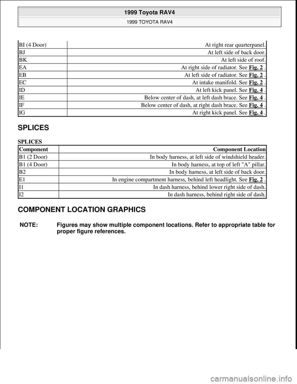
BI (4 Door)At right rear quarterpanel.
BJAt left side of back door.
BKAt left side of roof.
EAAt right side of radiator. See Fig. 2 .
EBAt left side of radiator. See Fig. 2 .
ECAt intake manifold. See Fig. 2 .
IDAt left kick panel. See Fig. 4 .
IEBelow center of dash, at left dash brace. See Fig. 4 .
IFBelow center of dash, at right dash brace. See Fig. 4 .
IGAt right kick panel. See Fig. 4 .
ComponentComponent Location
B1 (2 Door)In body harness, at left side of windshield header.
B1 (4 Door)In body harness, at top of left "A" pillar.
B2In body harness, at left side of back door.
E1In engine compartment harness, behind left headlight. See Fig. 2 .
I1In dash harness, behind lower right side of dash.
I2In dash harness, behind right side of dash.
NOTE: Figures may show multiple component locations. Refer to appropriate table for
proper figure references.
1999 Toyota RAV4
1999 TOYOTA RAV4
Microsoft
Sunday, November 22, 2009 10:17:32 AMPage 6 © 2005 Mitchell Repair Information Company, LLC.
Page 680 of 1632
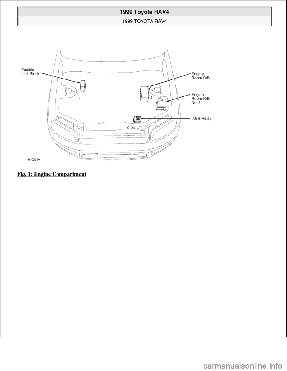
Fig. 1: Engine Compartment
1999 Toyota RAV4
1999 TOYOTA RAV4
Microsoft
Sunday, November 22, 2009 10:17:32 AMPage 7 © 2005 Mitchell Repair Information Company, LLC.