TOYOTA RAV4 2006 Service Repair Manual
Manufacturer: TOYOTA, Model Year: 2006, Model line: RAV4, Model: TOYOTA RAV4 2006Pages: 2000, PDF Size: 45.84 MB
Page 1901 of 2000
DOOR LOCK – POWER DOOR LOCK CONTROL SYSTEMDL–5
DL
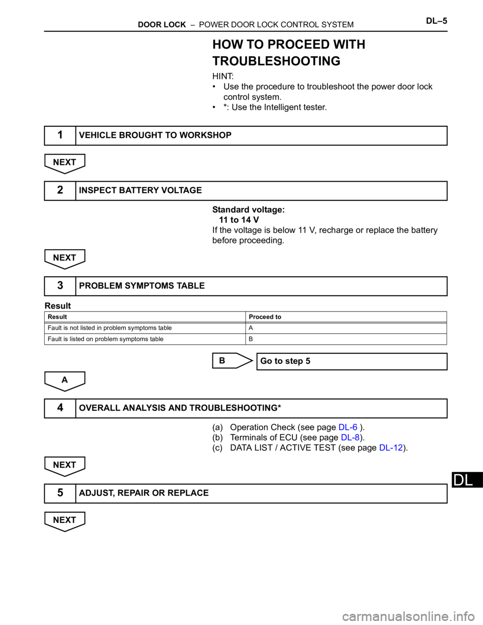
HOW TO PROCEED WITH
TROUBLESHOOTING
HINT:
• Use the procedure to troubleshoot the power door lock
control system.
• *: Use the Intelligent tester.
NEXT
Standard voltage:
11 to 14 V
If the voltage is below 11 V, recharge or replace the battery
before proceeding.
NEXT
Result
B
A
(a) Operation Check (see page DL-6 ).
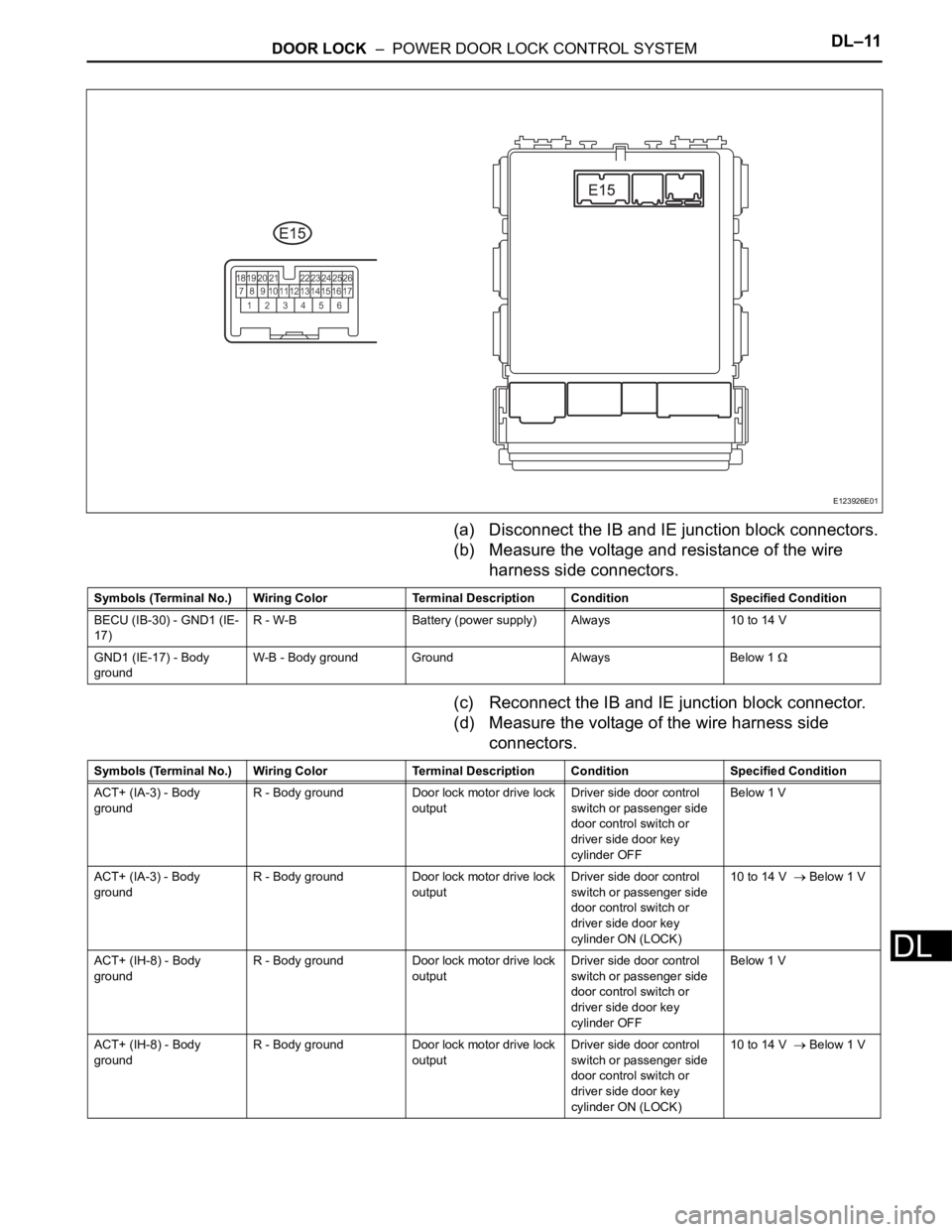
(b) Terminals of ECU (see page DL-8).
(c) DATA LIST / ACTIVE TEST (see page DL-12).
NEXT
NEXT
1VEHICLE BROUGHT TO WORKSHOP
2INSPECT BATTERY VOLTAGE
3PROBLEM SYMPTOMS TABLE
Result Proceed to
Fault is not listed in problem symptoms table A
Fault is listed on problem symptoms table B
Go to step 5
4OVERALL ANALYSIS AND TROUBLESHOOTING*
5ADJUST, REPAIR OR REPLACE
Page 1902 of 2000
DL–6DOOR LOCK – POWER DOOR LOCK CONTROL SYSTEM
DL
NEXT
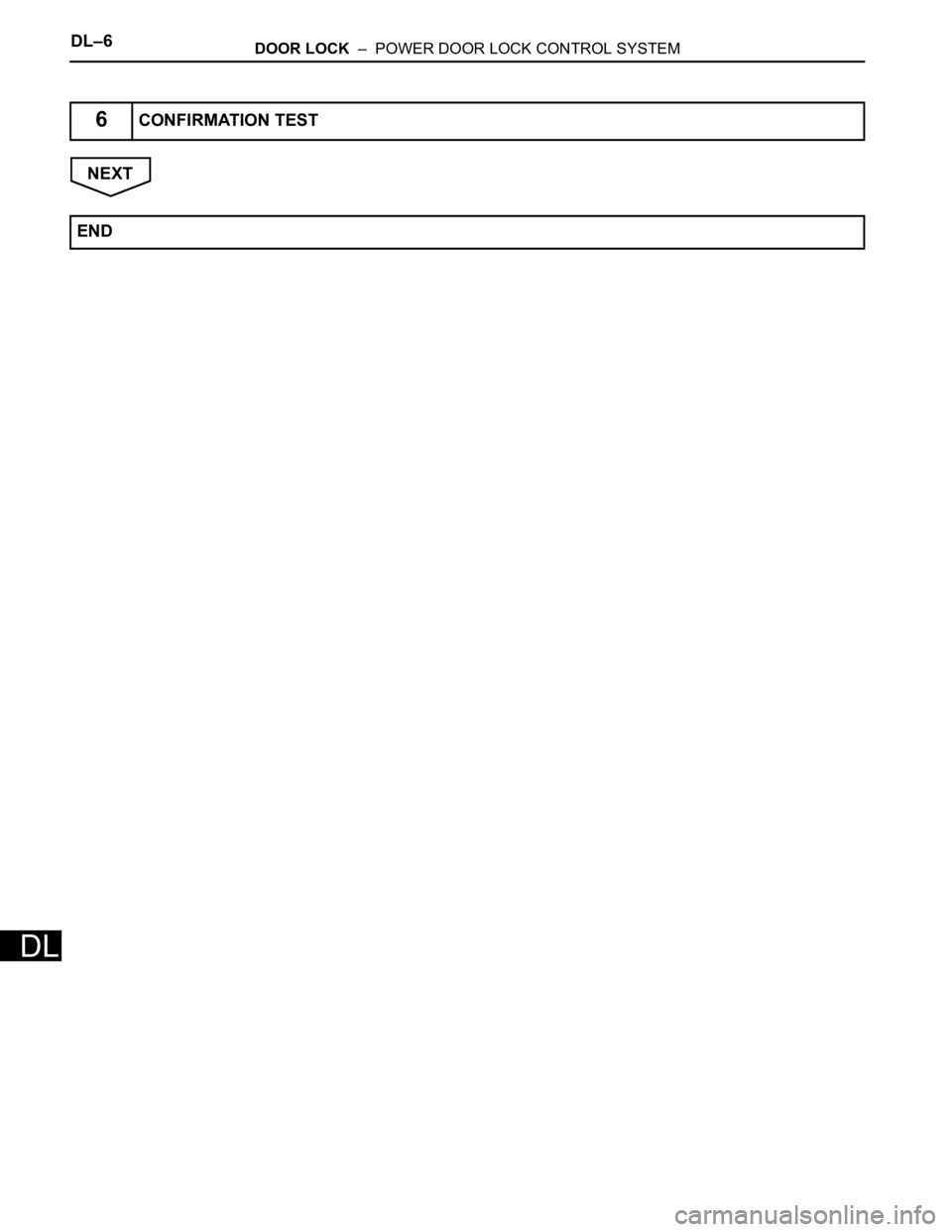
6CONFIRMATION TEST
END
Page 1903 of 2000

DOOR LOCK – POWER DOOR LOCK CONTROL SYSTEMDL–7
DL
OPERATION CHECK
1. CHECK ELECTRICAL DOOR LOCK OPERATION
(a) Check the basic function.
(1) Check that all doors lock when the door control
switch (for manual operation) is turned to LOCK
and all doors unlock when turned to UNLOCK.
(2) Check that all doors lock when the driver side
door lock key cylinder is turned to LOCK using
the key.
(3) Check that only the driver side door unlocks
when the driver side door lock key cylinder is
turned to UNLOCK and all doors unlock when
turned to UNLOCK once again within 3 seconds
using the key (2-step unlocking function).
(b) Check the key lock-in prevention.
NOTICE:
In order to prevent the key from being actually
locked-in, the inspection should be made with
the driver side door window open.
(1) Have the key inserted into the ignition key
cylinder.
(2) With the driver side door open, check that all
doors unlock immediately after the door lock
knob for the driver side door is turned to LOCK.
(3) With the driver side door open, check that all
doors unlock immediately after the door control
switch (for manual operation) is turned to LOCK.
(4) With the driver side door open, turn the driver
side door lock knob to LOCK and hold it for 2
seconds or more, and then close the driver side
door. Then check that all doors unlock.
Page 1904 of 2000

DL–8DOOR LOCK – POWER DOOR LOCK CONTROL SYSTEM
DL
CUSTOMIZE PARAMETERS
1. CUSTOMIZING FUNCTION WITH INTELLIGENT
TESTER (REFERENCE)
HINT:
The following item can be customized.
NOTICE:
• When the customer requests a change in a
function, first make sure that the function can be
customized.
• Make a note of the current settings before
customizing.
• When troubleshooting a function, first make sure
that the function is set to the default setting.
Power door lock control system:
Display (Item) Default Function Setting
UNLK/KEY TWICE ON Unlocks only driver side door
when driver side door key
cylinder turned to unlock once,
and unlocks all doors when
turned to unlock twice. For OFF
setting, turning it once unlocks all
doors.ON/OFF
Page 1905 of 2000
DOOR LOCK – POWER DOOR LOCK CONTROL SYSTEMDL–9
DL
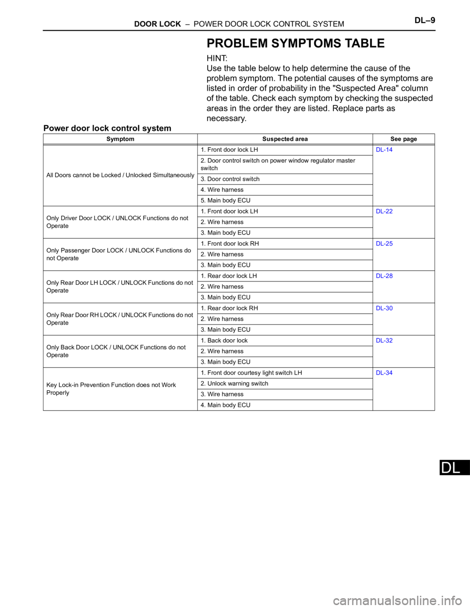
PROBLEM SYMPTOMS TABLE
HINT:
Use the table below to help determine the cause of the
problem symptom. The potential causes of the symptoms are
listed in order of probability in the "Suspected Area" column
of the table. Check each symptom by checking the suspected
areas in the order they are listed. Replace parts as
necessary.
Power door lock control system
Symptom Suspected area See page
All Doors cannot be Locked / Unlocked Simultaneously1. Front door lock LHDL-14
2. Door control switch on power window regulator master
switch
3. Door control switch
4. Wire harness
5. Main body ECU
Only Driver Door LOCK / UNLOCK Functions do not
Operate1. Front door lock LHDL-22
2. Wire harness
3. Main body ECU
Only Passenger Door LOCK / UNLOCK Functions do
not Operate1. Front door lock RHDL-25
2. Wire harness
3. Main body ECU
Only Rear Door LH LOCK / UNLOCK Functions do not
Operate1. Rear door lock LHDL-28
2. Wire harness
3. Main body ECU
Only Rear Door RH LOCK / UNLOCK Functions do not
Operate1. Rear door lock RHDL-30
2. Wire harness
3. Main body ECU
Only Back Door LOCK / UNLOCK Functions do not
Operate1. Back door lockDL-32
2. Wire harness
3. Main body ECU
Key Lock-in Prevention Function does not Work
Properly1. Front door courtesy light switch LHDL-34
2. Unlock warning switch
3. Wire harness
4. Main body ECU
Page 1906 of 2000
DL–10DOOR LOCK – POWER DOOR LOCK CONTROL SYSTEM
DL
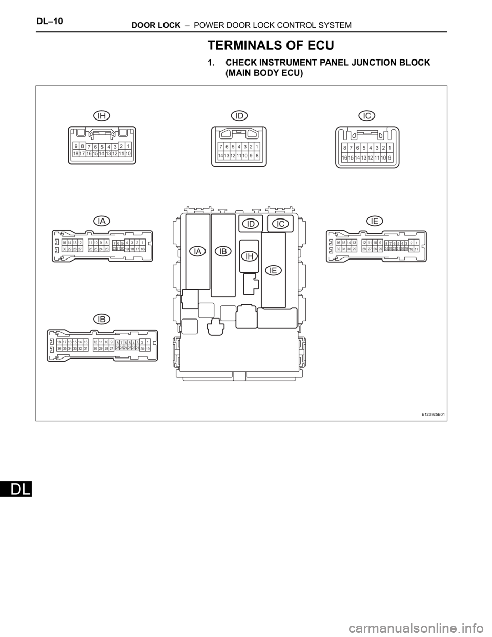
TERMINALS OF ECU
1. CHECK INSTRUMENT PANEL JUNCTION BLOCK
(MAIN BODY ECU)
E123925E01
Page 1907 of 2000
DOOR LOCK – POWER DOOR LOCK CONTROL SYSTEMDL–11
DL
(a) Disconnect the IB and IE junction block connectors.
(b) Measure the voltage and resistance of the wire
harness side connectors.
(c) Reconnect the IB and IE junction block connector.
(d) Measure the voltage of the wire harness side
connectors.
E123926E01
Symbols (Terminal No.) Wiring Color Terminal Description ConditionSpecified Condition
BECU (IB-30) - GND1 (IE-
17)R - W-B Battery (power supply) Always 10 to 14 V
GND1 (IE-17) - Body
groundW-B - Body ground Ground Always Below 1
Symbols (Terminal No.) Wiring Color Terminal Description ConditionSpecified Condition
ACT+ (IA-3) - Body
groundR - Body ground Door lock motor drive lock
outputDriver side door control
switch or passenger side
door control switch or
driver side door key
cylinder OFFBelow 1 V
ACT+ (IA-3) - Body
groundR - Body ground Door lock motor drive lock
outputDriver side door control
switch or passenger side
door control switch or
driver side door key
cylinder ON (LOCK)10 to 14 V
Below 1 V
ACT+ (IH-8) - Body
groundR - Body ground Door lock motor drive lock
outputDriver side door control
switch or passenger side
door control switch or
driver side door key
cylinder OFFBelow 1 V
ACT+ (IH-8) - Body
groundR - Body ground Door lock motor drive lock
outputDriver side door control
switch or passenger side
door control switch or
driver side door key
cylinder ON (LOCK)10 to 14 V
Below 1 V
Page 1908 of 2000

DL–12DOOR LOCK – POWER DOOR LOCK CONTROL SYSTEM
DL
ACT+ (IH-17) - Body
groundR - Body ground Door lock motor drive lock
outputDriver side door control
switch or passenger side
door control switch or
driver side door key
cylinder OFFBelow 1 V
ACT+ (IH-17) - Body
groundR - Body ground Door lock motor drive lock
outputDriver side door control
switch or passenger side
door control switch or
driver side door key
cylinder ON (LOCK)10 to 14 V
Below 1 V
ACT- (IA-4) - Body ground BR- Body ground Door lock motor drive
unlock outputDriver side door control
switch or passenger side
door control switch or
driver side door key
cylinder OFFBelow 1 V
ACT- (IA-4) - Body ground BR - Body ground Door lock motor drive
unlock outputDriver side door control
switch or passenger side
door control switch or
driver side door key
cylinder ON (UNLOCK)10 to 14 V
Below 1 V
ACT- (IH-18) - Body
groundB - Body ground Door lock motor drive
unlock outputDriver side door control
switch or passenger side
door control switch or
driver side door key
cylinder OFFBelow 1 V
ACT- (IH-18) - Body
groundB - Body ground Door lock motor drive
unlock outputDriver side door control
switch or passenger side
door control switch or
driver side door key
cylinder ON (UNLOCK)10 to 14 V
Below 1 V
KSW (IE-26) - Body
groundL- Body ground Key unlock warning switch
inputKey is inserted in ignition
key cylinderBelow 1 V
KSW (IE-26) - Body
groundL- Body ground Key unlock warning switch
inputNo key is in ignition key
cylinder10 to 14 V
UL1 (IH-5) - Body ground B - Body ground Driver side manual unlock
switch inputDriver side door control
switch OFFBelow 1 V
UL1 (IH-5) - Body ground B - Body ground Driver side manual unlock
switch inputDriver side door control
switch ON (UNLOCK)10 to 14 V
Below 1 V
UL1 (IH-14) - Body ground O - Body ground Passenger side manual
unlock switch inputPassenger side door
control switch OFFBelow 1 V
UL1 (IH-14) - Body ground O - Body ground Passenger side manual
unlock switch inputPassenger side door
control switch ON
(UNLOCK)10 to 14 V
Below 1 V
L1 (IH-4) - Body ground P - Body ground Driver side manual lock
switch inputDriver side door control
switch OFFBelow 1 V
L1 (IH-4) - Body ground P - Body ground Driver side manual lock
switch inputDriver side door control
switch ON (LOCK)10 to 14 V
Below 1 V
L1 (IH-13) - Body ground V - Body ground Passenger side manual
lock switch inputPassenger side door
control switch OFFBelow 1 V
L1 (IH-13) - Body ground V - Body ground Passenger side manual
lock switch inputPassenger side door
control switch ON (LOCK)10 to 14 V
Below 1 V
L2 (IH-7) - Body ground SB - Body ground Driver side Key-linked
operated lock switch inputDriver side door key
cylinder OFFBelow 1 V
L2 (IH-7) - Body ground SB - Body ground Driver side Key-linked
operated lock switch inputDriver side door key
cylinder ON (LOCK)10 to 14 V
Below 1 V
PCTY (IC-14) - Body
groundBR - Body ground Passenger door courtesy
switch inputPassenger side door
closed10 to 14 V
PCTY (IC-14) - Body
groundBR - Body ground Passenger door courtesy
switch inputPassenger side door open Below 1 V
RRCY (ID-7) - Body
groundLC - Body ground Rear door courtesy switch
LH inputRear RH door closed 10 to 14 V Symbols (Terminal No.) Wiring Color Terminal Description ConditionSpecified Condition
Page 1909 of 2000

DOOR LOCK – POWER DOOR LOCK CONTROL SYSTEMDL–13
DL
RRCY (ID-7) - Body
groundLC - Body ground Rear door courtesy switch
LH inputRear RH door open Below 1 V
BCTY (IA-7) - Body
groundLG - Body ground Back door courtesy switch
inputBack door closed 10 to 14 V
BCTY (IA-7) - Body
groundLG - Body ground Back door courtesy switch
inputBack door open Below 1 V
DCTY (IA-21) - Body
groundW - Body ground Driver side door courtesy
switch inputDriver side door open 10 to 14 V
DCTY (IA-21) - Body
groundW - Body ground Driver side door courtesy
switch inputDriver side door closed Below 1 V
DCTY (IC-6) - Body
groundBR - Body ground Driver side door courtesy
switch inputDriver side door open 10 to 14 V
DCTY (IC-6) - Body
groundBR - Body ground Driver side door courtesy
switch inputDriver side door closed Below 1 V
ACTD (E15-5) - Body
groundB - Body ground Driver side door unlock
motor driveDriver side door control
switch or door control
switch or driver side door
key cylinder OFFBelow 1 V
ACTD (E15-5) - Body
groundB - Body ground Driver side door unlock
motor driveDriver side door control
switch or door control
switch or driver side door
key cylinder ON
(UNLOCK)10 to 14 V
Below 1 V
LSWP (E15-10) - Body
groundY - Body ground Passenger side door lock
position switch inputPassenger side door
UNLOCK10 to 14 V
LSWP (E15-10) - Body
groundY - Body ground Passenger side door lock
position switch inputPassenger side door
LOCKBelow 1 V
UL3 (E15-9) - Body
groundLG - Body ground Driver side door key-linked
operated door unlock
switch inputDriver side door key
cylinder OFFBelow 1 V
UL3 (E15-9) - Body
groundLG - Body ground Driver side door key-linked
operated door unlock
switch inputDriver side door key
cylinder ON (LOCK)10 to 14 V
Below 1 V Symbols (Terminal No.) Wiring Color Terminal Description ConditionSpecified Condition
Page 1910 of 2000
DL–14DOOR LOCK – POWER DOOR LOCK CONTROL SYSTEM
DL
DIAGNOSIS SYSTEM
1. DESCRIPTION
Power door lock control system data can be read in the
Data Link Connector 3 (DLC3) of the vehicle. When the
system seems to be malfunctioning, use the intelligent
tester to check for malfunctions and perform repairs.
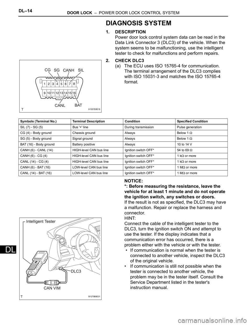
2. CHECK DLC3
(a) The ECU uses ISO 15765-4 for communication.
The terminal arrangement of the DLC3 complies
with ISO 15031-3 and matches the ISO 15765-4
format.
NOTICE:
*: Before measuring the resistance, leave the
vehicle for at least 1 minute and do not operate
the ignition switch, any switches or doors.
If the result is not as specified, the DLC3 may have
a malfunction. Repair or replace the harness and
connector.
HINT:
Connect the cable of the intelligent tester to the
DLC3, turn the ignition switch ON and attempt to
use the tester. If the display indicates that a
communication error has occurred, there is a
problem either with the vehicle or with the tester.
• If communication is normal when the tester is
connected to another vehicle, inspect the DLC3
of the original vehicle.
• If communication is still not possible when the
tester is connected to another vehicle, the
problem may be in the tester itself. Consult the
Service Department listed in the tester's
instruction manual.
H100769E16
Symbols (Terminal No.) Terminal Description Condition Specified Condition
SIL (7) - SG (5) Bus '+' line During transmission Pulse generation
CG (4) - Body ground Chassis ground Always Below 1
SG (5) - Body ground Signal ground Always Below 1
BAT (16) - Body ground Battery positive Always 10 to 14 V
CANH (6) - CANL (14) HIGH-level CAN bus line Ignition switch OFF*54 to 69
CANH (6) - CG (4) HIGH-level CAN bus line Ignition switch OFF* 1 k or more
CANL (14) - CG (4) HIGH-level CAN bus line Ignition switch OFF* 1 k
or more
CANH (6) - BAT (16) LOW-level CAN bus line Ignition switch OFF* 1 M
or more
CANL (14) - BAT (16) LOW-level CAN bus line Ignition switch OFF* 1 M
or more
B127989E01