TOYOTA RAV4 2006 Service Repair Manual
Manufacturer: TOYOTA, Model Year: 2006,
Model line: RAV4,
Model: TOYOTA RAV4 2006
Pages: 2000, PDF Size: 45.84 MB
TOYOTA RAV4 2006 Service Repair Manual
RAV4 2006
TOYOTA
TOYOTA
https://www.carmanualsonline.info/img/14/57463/w960_57463-0.png
TOYOTA RAV4 2006 Service Repair Manual
Trending: lights, washer fluid, recommended oil, torque, Engine cover, water drain, jump start
Page 1921 of 2000
DOOR LOCK – POWER DOOR LOCK CONTROL SYSTEMDL–25
DL
DESCRIPTION
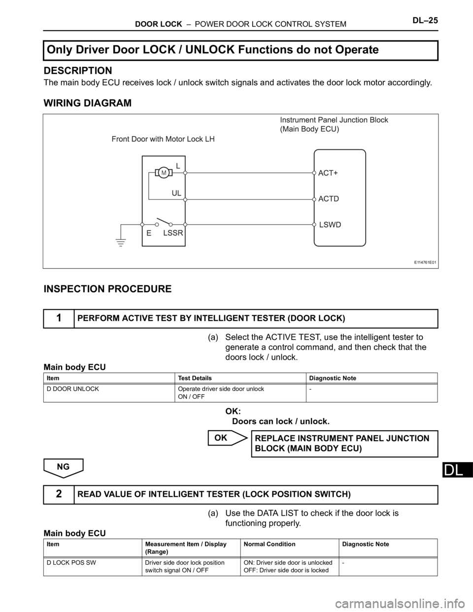
The main body ECU receives lock / unlock switch signals and activates the door lock motor accordingly.
WIRING DIAGRAM
INSPECTION PROCEDURE
(a) Select the ACTIVE TEST, use the intelligent tester to
generate a control command, and then check that the
doors lock / unlock.
Main body ECU
OK:
Doors can lock / unlock.
OK
NG
(a) Use the DATA LIST to check if the door lock is
functioning properly.
Main body ECU
Only Driver Door LOCK / UNLOCK Functions do not Operate
1PERFORM ACTIVE TEST BY INTELLIGENT TESTER (DOOR LOCK)
E114761E01
Item Test Details Diagnostic Note
D DOOR UNLOCK Operate driver side door unlock
ON / OFF-
REPLACE INSTRUMENT PANEL JUNCTION
BLOCK (MAIN BODY ECU)
2READ VALUE OF INTELLIGENT TESTER (LOCK POSITION SWITCH)
Item Measurement Item / Display
(Range)Normal Condition Diagnostic Note
D LOCK POS SW Driver side door lock position
switch signal ON / OFFON: Driver side door is unlocked
OFF: Driver side door is locked-
Page 1922 of 2000
DL–26DOOR LOCK – POWER DOOR LOCK CONTROL SYSTEM
DL
OK:
When the door lock is operating, the intelligent
tester should display as shown in the table.
OK
NG
(a) Apply the battery voltage to the motor terminals and
check the operation of the door lock motor.
OK
(b) Measure the resistance of the door lock position switch.
Standard resistance
NG
OKREPLACE INSTRUMENT PANEL JUNCTION
BLOCK (MAIN BODY ECU)
3INSPECT FRONT DOOR WITH MOTOR LOCK ASSEMBLY LH
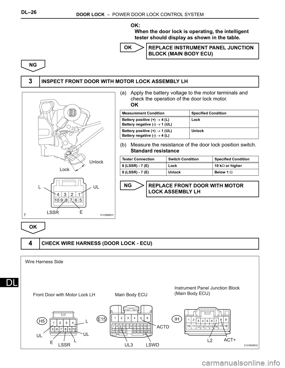
E123888E01
Measurement Condition Specified Condition
Battery positive (+)
4 (L)
Battery negative (-)
1 (UL)Lock
Battery positive (+)
1 (UL)
Battery negative (-)
4 (L)Unlock
Tester Connection Switch Condition Specified Condition
8 (LSSR) - 7 (E) Lock 10 k
or higher
8 (LSSR) - 7 (E) Unlock Below 1
REPLACE FRONT DOOR WITH MOTOR
LOCK ASSEMBLY LH
4CHECK WIRE HARNESS (DOOR LOCK - ECU)
E123902E02
Page 1923 of 2000
DOOR LOCK – POWER DOOR LOCK CONTROL SYSTEMDL–27
DL
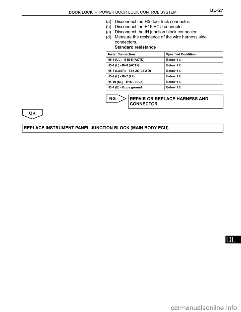
(a) Disconnect the H5 door lock connector.
(b) Disconnect the E15 ECU connector.
(c) Disconnect the IH junction block connector.
(d) Measure the resistance of the wire harness side
connectors.
Standard resistance
NG
OK
Tester Connection Specified Condition
H5-1 (UL) - E15-5 (ACTD) Below 1
H5-4 (L) - IH-8 (ACT+) Below 1
H5-8 (LSSR) - E15-25 (LSWD) Below 1
H5-9 (L) - IH-7 (L2) Below 1
H5-10 (UL) - E15-9 (UL3) Below 1
H5-7 (E) - Body ground Below 1
REPAIR OR REPLACE HARNESS AND
CONNECTOR
REPLACE INSTRUMENT PANEL JUNCTION BLOCK (MAIN BODY ECU)
Page 1924 of 2000
DL–28DOOR LOCK – POWER DOOR LOCK CONTROL SYSTEM
DL
DESCRIPTION
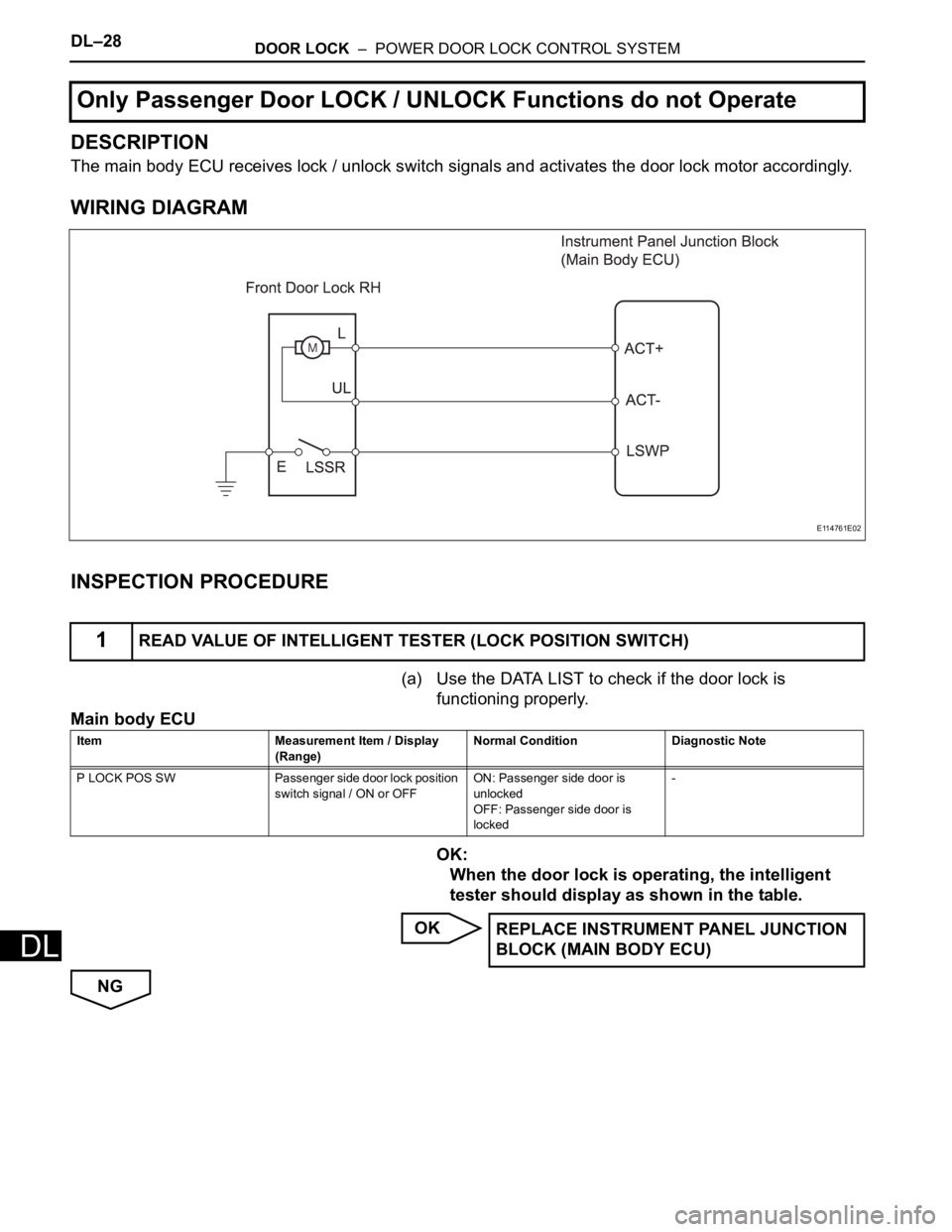
The main body ECU receives lock / unlock switch signals and activates the door lock motor accordingly.
WIRING DIAGRAM
INSPECTION PROCEDURE
(a) Use the DATA LIST to check if the door lock is
functioning properly.
Main body ECU
OK:
When the door lock is operating, the intelligent
tester should display as shown in the table.
OK
NG
Only Passenger Door LOCK / UNLOCK Functions do not Operate
1READ VALUE OF INTELLIGENT TESTER (LOCK POSITION SWITCH)
E114761E02
Item Measurement Item / Display
(Range)Normal Condition Diagnostic Note
P LOCK POS SW Passenger side door lock position
switch signal / ON or OFFON: Passenger side door is
unlocked
OFF: Passenger side door is
locked-
REPLACE INSTRUMENT PANEL JUNCTION
BLOCK (MAIN BODY ECU)
Page 1925 of 2000
DOOR LOCK – POWER DOOR LOCK CONTROL SYSTEMDL–29
DL
(a) Apply the battery voltage to the door lock motor and
check the operation of the door lock motor.
OK
(b) Measure the resistance of the door lock position switch.
Standard resistance
NG
OK
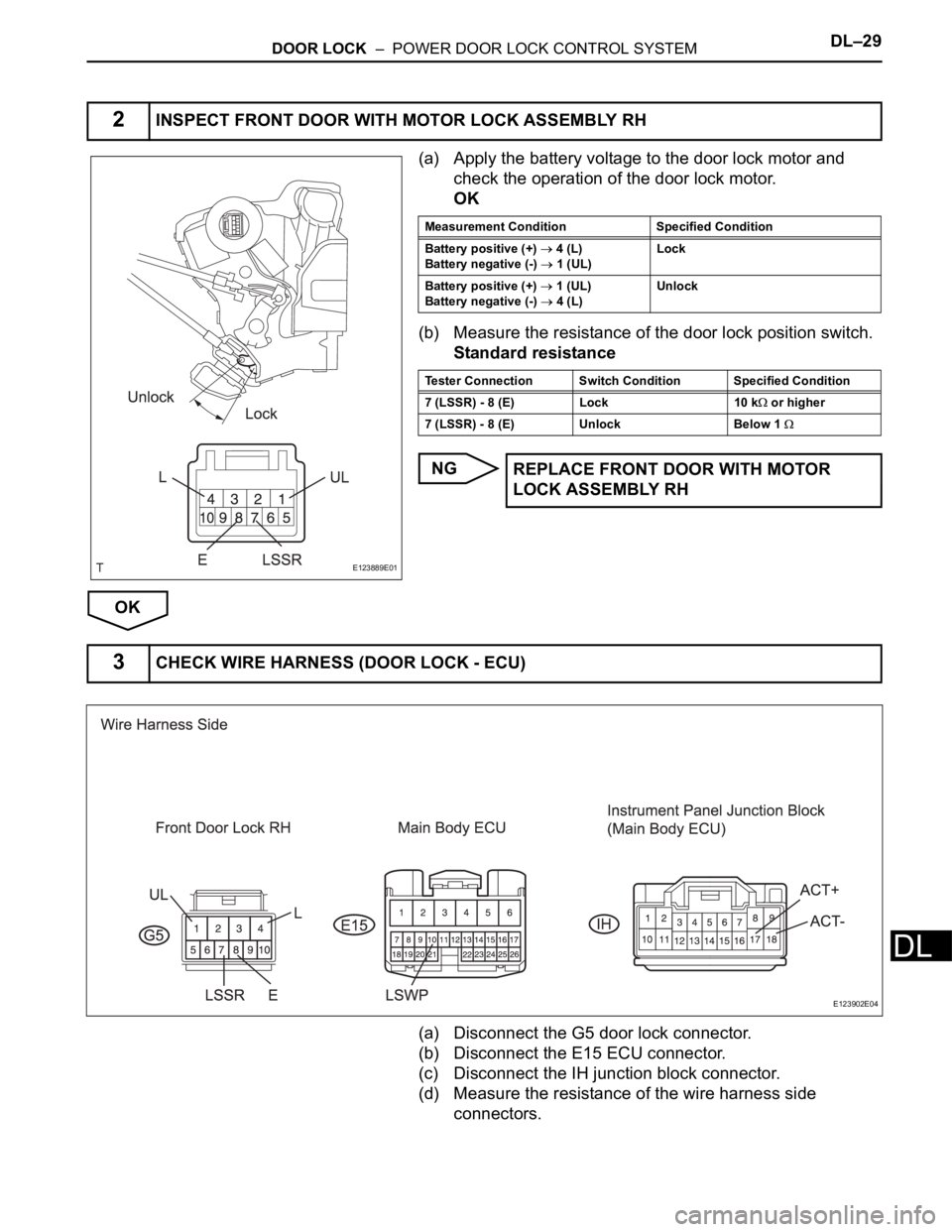
(a) Disconnect the G5 door lock connector.
(b) Disconnect the E15 ECU connector.
(c) Disconnect the IH junction block connector.
(d) Measure the resistance of the wire harness side
connectors.
2INSPECT FRONT DOOR WITH MOTOR LOCK ASSEMBLY RH
E123889E01
Measurement Condition Specified Condition
Battery positive (+)
4 (L)
Battery negative (-) 1 (UL)Lock
Battery positive (+)
1 (UL)
Battery negative (-) 4 (L)Unlock
Tester Connection Switch Condition Specified Condition
7 (LSSR) - 8 (E) Lock 10 k
or higher
7 (LSSR) - 8 (E) Unlock Below 1
REPLACE FRONT DOOR WITH MOTOR
LOCK ASSEMBLY RH
3CHECK WIRE HARNESS (DOOR LOCK - ECU)
E123902E04
Page 1926 of 2000
DL–30DOOR LOCK – POWER DOOR LOCK CONTROL SYSTEM
DL
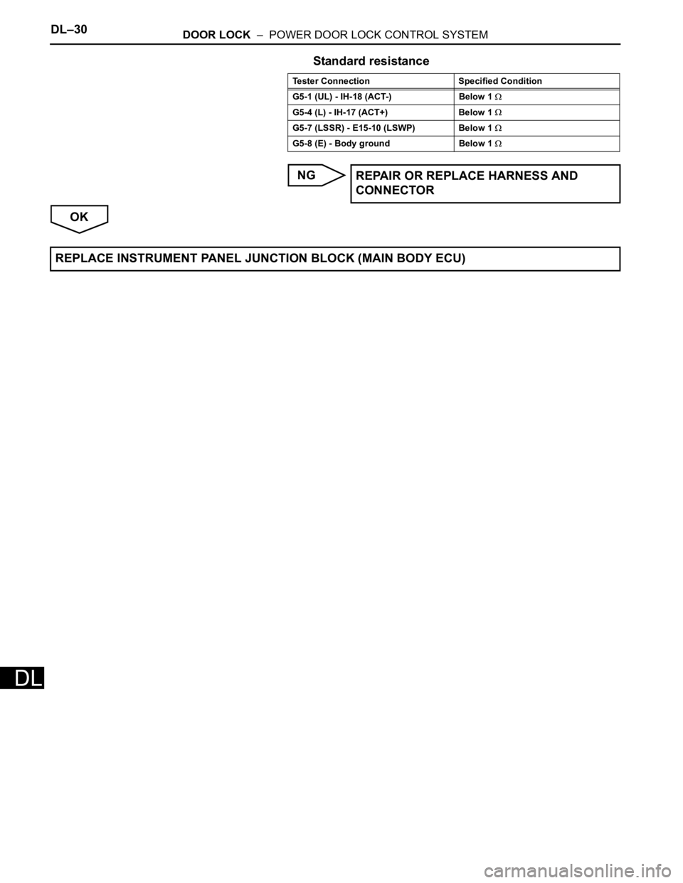
Standard resistance
NG
OK
Tester Connection Specified Condition
G5-1 (UL) - IH-18 (ACT-) Below 1
G5-4 (L) - IH-17 (ACT+) Below 1
G5-7 (LSSR) - E15-10 (LSWP) Below 1
G5-8 (E) - Body ground Below 1
REPAIR OR REPLACE HARNESS AND
CONNECTOR
REPLACE INSTRUMENT PANEL JUNCTION BLOCK (MAIN BODY ECU)
Page 1927 of 2000
DOOR LOCK – POWER DOOR LOCK CONTROL SYSTEMDL–31
DL
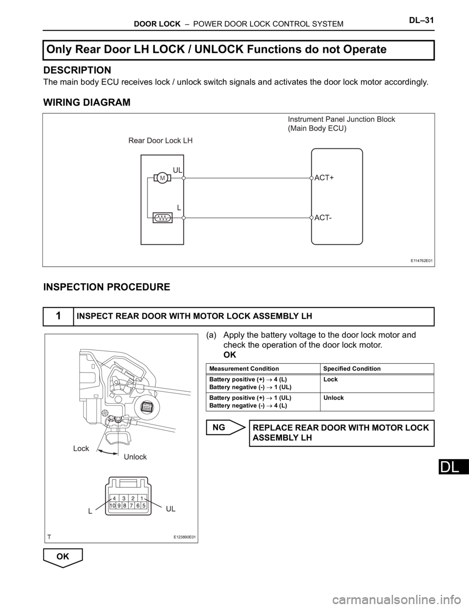
DESCRIPTION
The main body ECU receives lock / unlock switch signals and activates the door lock motor accordingly.
WIRING DIAGRAM
INSPECTION PROCEDURE
(a) Apply the battery voltage to the door lock motor and
check the operation of the door lock motor.
OK
NG
OK
Only Rear Door LH LOCK / UNLOCK Functions do not Operate
1INSPECT REAR DOOR WITH MOTOR LOCK ASSEMBLY LH
E114762E01
E123890E01
Measurement Condition Specified Condition
Battery positive (+)
4 (L)
Battery negative (-)
1 (UL)Lock
Battery positive (+)
1 (UL)
Battery negative (-)
4 (L)Unlock
REPLACE REAR DOOR WITH MOTOR LOCK
ASSEMBLY LH
Page 1928 of 2000
DL–32DOOR LOCK – POWER DOOR LOCK CONTROL SYSTEM
DL
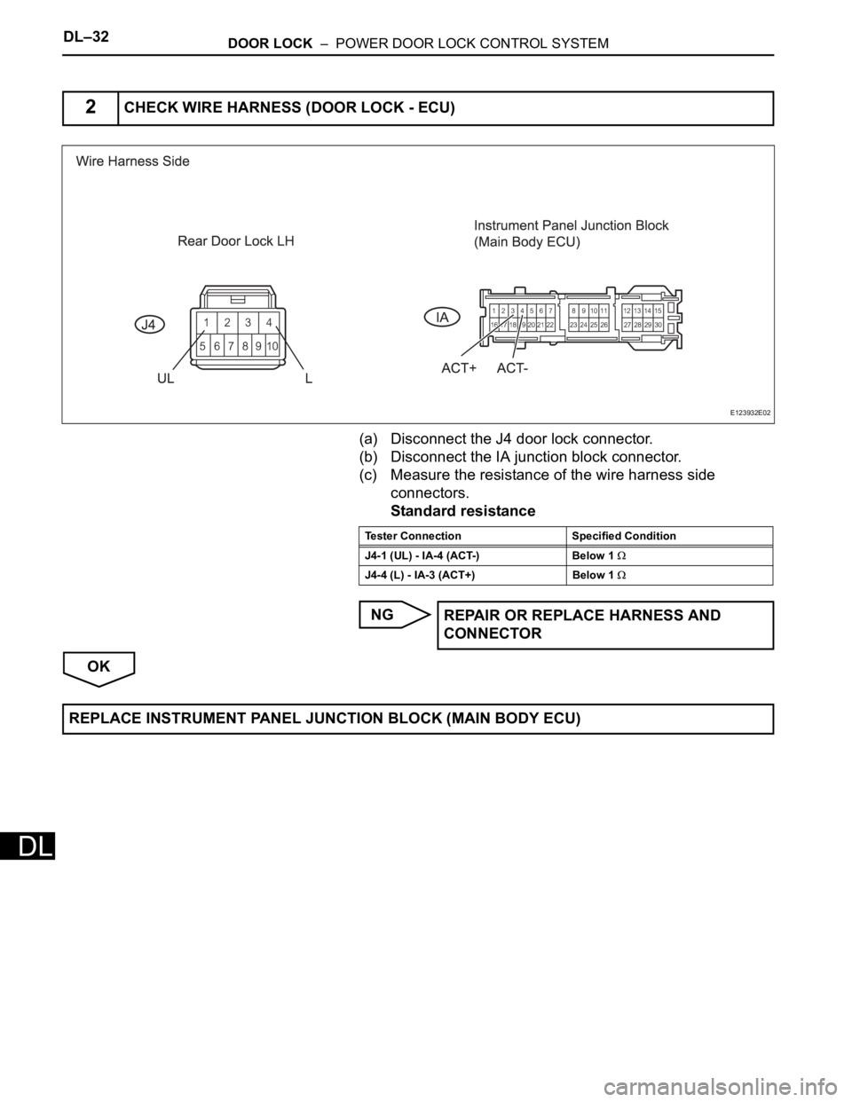
(a) Disconnect the J4 door lock connector.
(b) Disconnect the IA junction block connector.
(c) Measure the resistance of the wire harness side
connectors.
Standard resistance
NG
OK
2CHECK WIRE HARNESS (DOOR LOCK - ECU)
E123932E02
Tester Connection Specified Condition
J4-1 (UL) - IA-4 (ACT-) Below 1
J4-4 (L) - IA-3 (ACT+) Below 1
REPAIR OR REPLACE HARNESS AND
CONNECTOR
REPLACE INSTRUMENT PANEL JUNCTION BLOCK (MAIN BODY ECU)
Page 1929 of 2000
DOOR LOCK – POWER DOOR LOCK CONTROL SYSTEMDL–33
DL
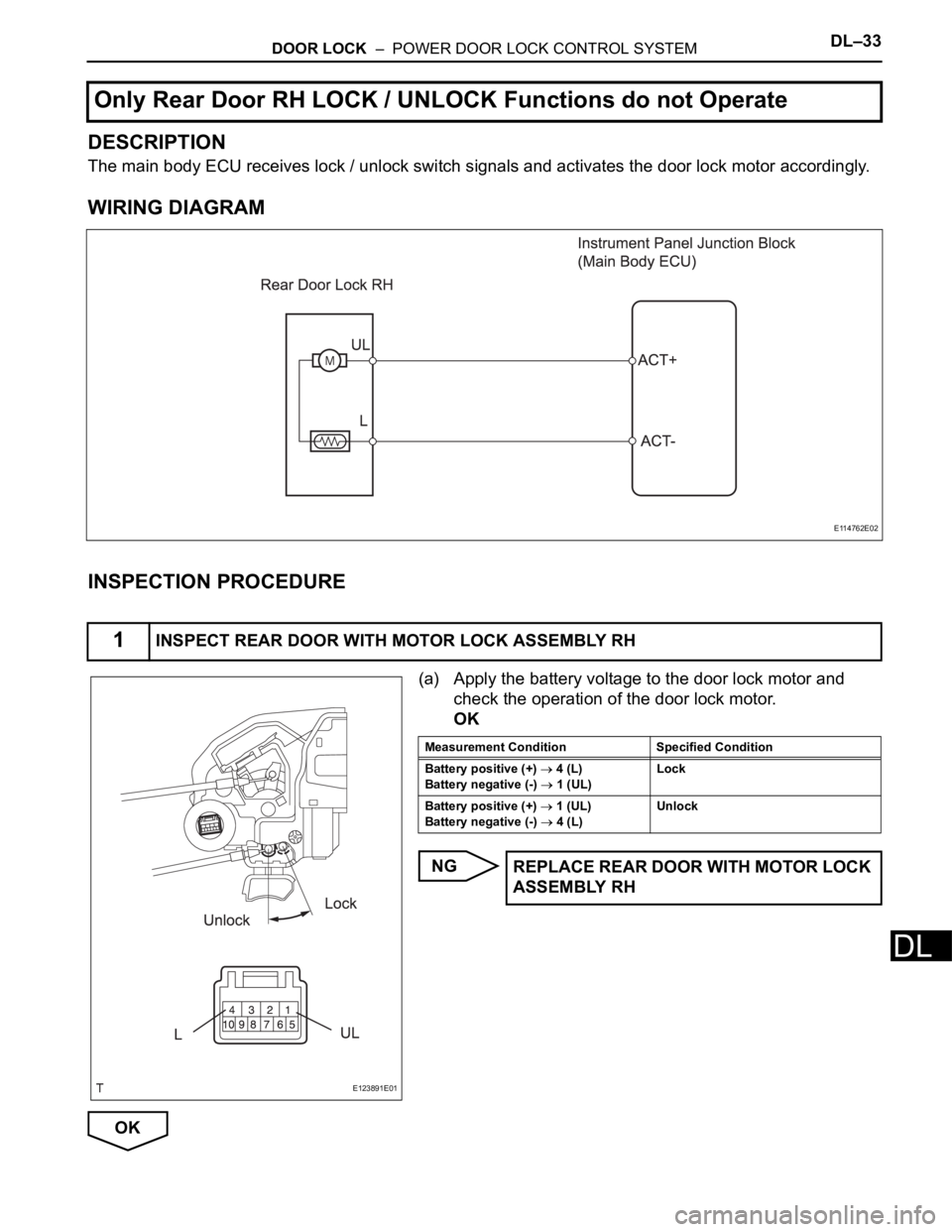
DESCRIPTION
The main body ECU receives lock / unlock switch signals and activates the door lock motor accordingly.
WIRING DIAGRAM
INSPECTION PROCEDURE
(a) Apply the battery voltage to the door lock motor and
check the operation of the door lock motor.
OK
NG
OK
Only Rear Door RH LOCK / UNLOCK Functions do not Operate
1INSPECT REAR DOOR WITH MOTOR LOCK ASSEMBLY RH
E114762E02
E123891E01
Measurement Condition Specified Condition
Battery positive (+)
4 (L)
Battery negative (-)
1 (UL)Lock
Battery positive (+)
1 (UL)
Battery negative (-)
4 (L)Unlock
REPLACE REAR DOOR WITH MOTOR LOCK
ASSEMBLY RH
Page 1930 of 2000
DL–34DOOR LOCK – POWER DOOR LOCK CONTROL SYSTEM
DL
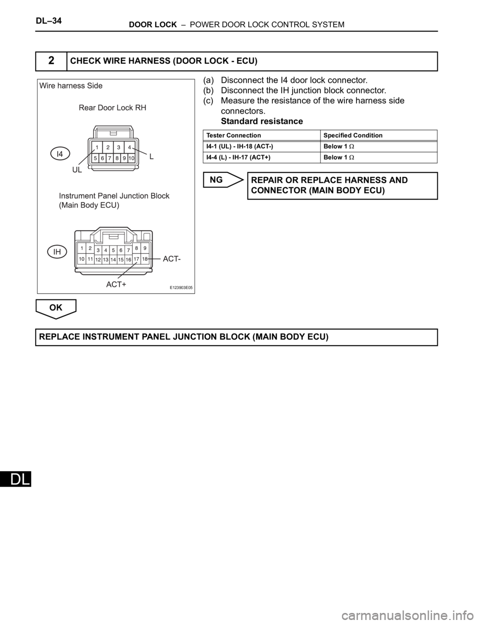
(a) Disconnect the I4 door lock connector.
(b) Disconnect the IH junction block connector.
(c) Measure the resistance of the wire harness side
connectors.
Standard resistance
NG
OK
2CHECK WIRE HARNESS (DOOR LOCK - ECU)
E123903E05
Tester Connection Specified Condition
I4-1 (UL) - IH-18 (ACT-) Below 1
I4-4 (L) - IH-17 (ACT+) Below 1
REPAIR OR REPLACE HARNESS AND
CONNECTOR (MAIN BODY ECU)
REPLACE INSTRUMENT PANEL JUNCTION BLOCK (MAIN BODY ECU)
Trending: wipers, refrigeration system, Ws atf, power steering fluid, drain bolt, valve body, wiper fluid

