TOYOTA RAV4 2006 Service Repair Manual
Manufacturer: TOYOTA, Model Year: 2006, Model line: RAV4, Model: TOYOTA RAV4 2006Pages: 2000, PDF Size: 45.84 MB
Page 431 of 2000
SUPPLEMENTAL RESTRAINT SYSTEM – AIRBAG SYSTEMRS–21
RS
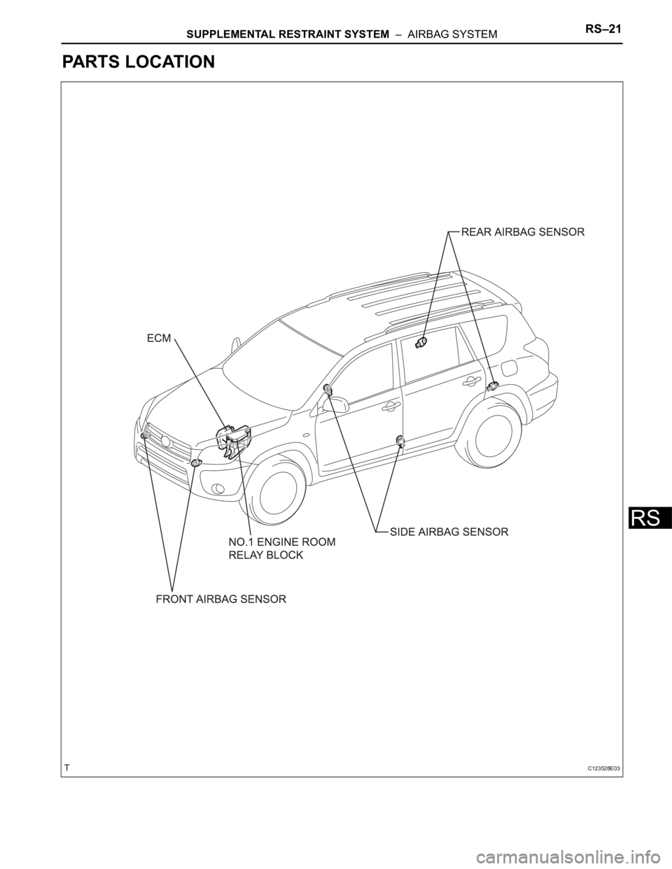
PARTS LOCATION
C123528E03
Page 432 of 2000
RS–22SUPPLEMENTAL RESTRAINT SYSTEM – AIRBAG SYSTEM
RS
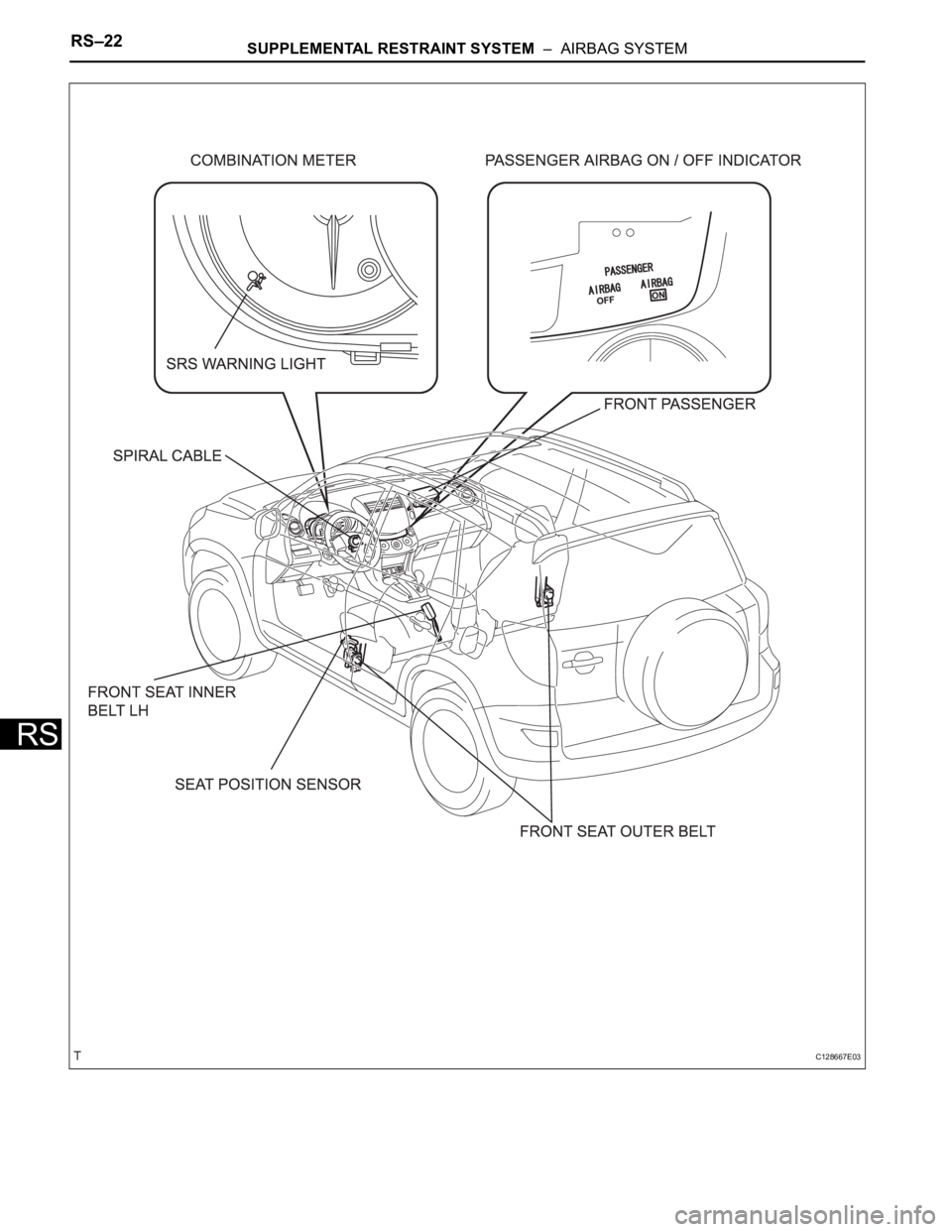
C128667E03
Page 433 of 2000
SUPPLEMENTAL RESTRAINT SYSTEM – AIRBAG SYSTEMRS–23
RS
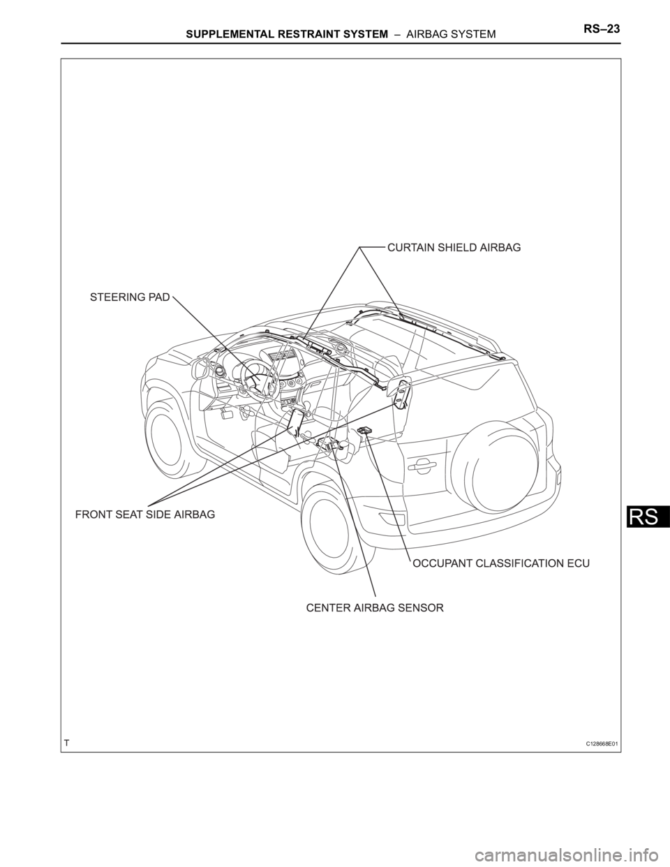
C128668E01
Page 434 of 2000
SUPPLEMENTAL RESTRAINT SYSTEM – SIDE AIRBAG SENSORRS–383
RS
REMOVAL
CAUTION:
Be sure to read the precautionary notices concerning the
SRS airbag system before servicing it (see page RS-1).
HINT:
• Use the same procedures for the RH side and LH side.
• The procedures listed below are for the LH side.
1. DISCONNECT CABLE FROM NEGATIVE BATTERY
TERMINAL
CAUTION:
Wait at least 90 seconds after disconnecting the
cable from the negative (-) battery terminal to
prevent airbag and seat belt pretensioner activation.
2. REMOVE FRONT DOOR SCUFF PLATE LH (See page
IR-26)
3. REMOVE REAR DOOR SCUFF PLATE LH (See page
IR-57)
4. REMOVE CENTER PILLAR GARNISH LOWER LH
(See page SB-27)
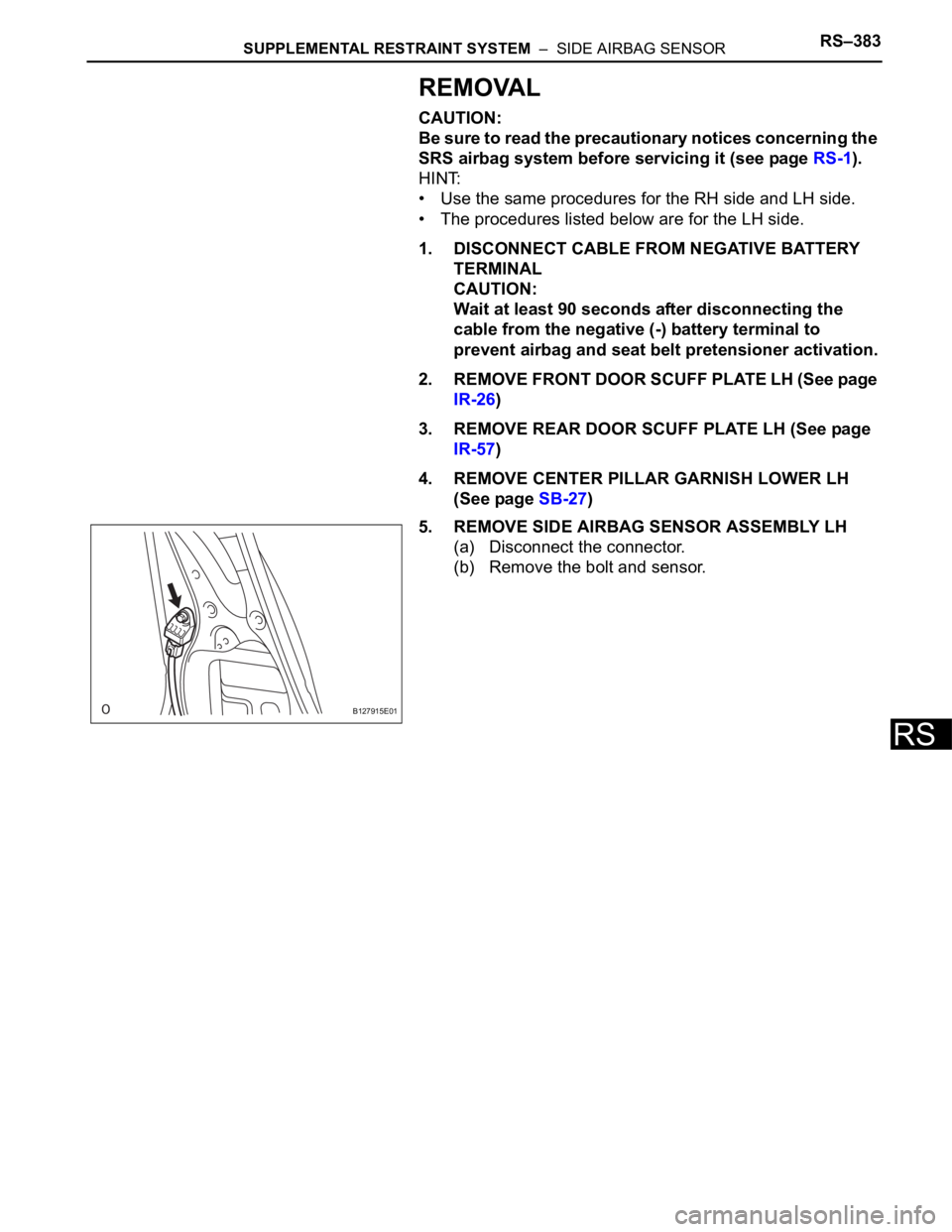
5. REMOVE SIDE AIRBAG SENSOR ASSEMBLY LH
(a) Disconnect the connector.
(b) Remove the bolt and sensor.
B127915E01
Page 435 of 2000
RS–384SUPPLEMENTAL RESTRAINT SYSTEM – SIDE AIRBAG SENSOR
RS
INSTALLATION
HINT:
• Use the same procedures for the RH side and LH side.
• The procedures listed below are for the LH side.
CAUTION:
Be sure to read the precautionary notices concerning the
SRS airbag system before servicing it (see page RS-1).
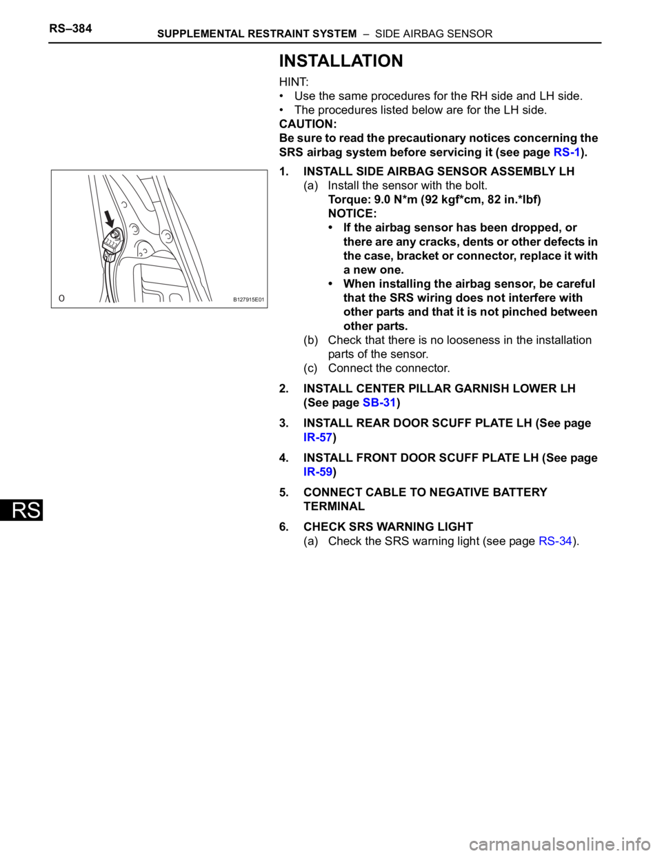
1. INSTALL SIDE AIRBAG SENSOR ASSEMBLY LH
(a) Install the sensor with the bolt.
Torque: 9.0 N*m (92 kgf*cm, 82 in.*lbf)
NOTICE:
• If the airbag sensor has been dropped, or
there are any cracks, dents or other defects in
the case, bracket or connector, replace it with
a new one.
• When installing the airbag sensor, be careful
that the SRS wiring does not interfere with
other parts and that it is not pinched between
other parts.
(b) Check that there is no looseness in the installation
parts of the sensor.
(c) Connect the connector.
2. INSTALL CENTER PILLAR GARNISH LOWER LH
(See page SB-31)
3. INSTALL REAR DOOR SCUFF PLATE LH (See page
IR-57)
4. INSTALL FRONT DOOR SCUFF PLATE LH (See page
IR-59)
5. CONNECT CABLE TO NEGATIVE BATTERY
TERMINAL
6. CHECK SRS WARNING LIGHT
(a) Check the SRS warning light (see page RS-34).
B127915E01
Page 436 of 2000

SEAT BELT – SEAT BELT WARNING SYSTEMSB–3
SB
SYSTEM DESCRIPTION
1. DRIVER SEAT BELT WARNING LIGHT
(a) When the driver seat belt is not fastened with the
ignition switch ON, the driver seat belt warning light
on the combination meter comes on to inform the
driver. The center airbag sensor detects the driver
seat belt status and sends signals to the
combination meter through the CAN bus line.
2. PASSENGER SEAT BELT WARNING LIGHT
(a) for Automatic air conditioning system:
When the passenger seat belt is not fastened with
the ignition switch ON and the passenger seat
occupied, check that the passenger seat belt
warning light on the heater control panel display
blinks. The combination meter detects the
passenger seat belt status and whether the
passenger seat is occupied.
(b) for Manual air conditioning system:
When the passenger seat belt is not fastened with
the ignition switch ON and the passenger seat
occupied, check that the passenger seat belt
warning light on the clock panel blinks. The
combination meter detects the passenger seat belt
status and whether the passenger seat is occupied.
Page 437 of 2000
SB–4SEAT BELT – SEAT BELT WARNING SYSTEM
SB
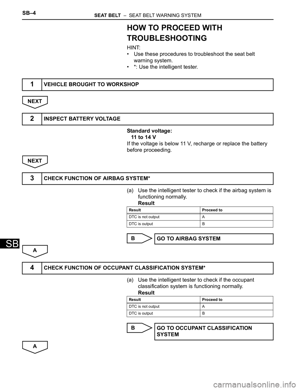
HOW TO PROCEED WITH
TROUBLESHOOTING
HINT:
• Use these procedures to troubleshoot the seat belt
warning system.
• *: Use the intelligent tester.
NEXT
Standard voltage:
11 to 14 V
If the voltage is below 11 V, recharge or replace the battery
before proceeding.
NEXT
(a) Use the intelligent tester to check if the airbag system is
functioning normally.
Result
B
A
(a) Use the intelligent tester to check if the occupant
classification system is functioning normally.
Result
B
A
1VEHICLE BROUGHT TO WORKSHOP
2INSPECT BATTERY VOLTAGE
3CHECK FUNCTION OF AIRBAG SYSTEM*
Result Proceed to
DTC is not output A
DTC is output B
GO TO AIRBAG SYSTEM
4CHECK FUNCTION OF OCCUPANT CLASSIFICATION SYSTEM*
Result Proceed to
DTC is not output A
DTC is output B
GO TO OCCUPANT CLASSIFICATION
SYSTEM
Page 438 of 2000
SEAT BELT – SEAT BELT WARNING SYSTEMSB–5
SB
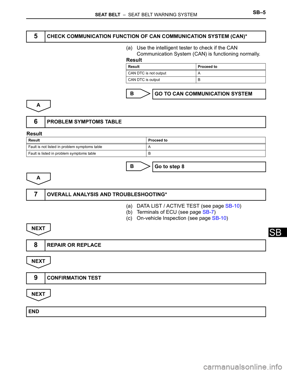
(a) Use the intelligent tester to check if the CAN
Communication System (CAN) is functioning normally.
Result
B
A
Result
B
A
(a) DATA LIST / ACTIVE TEST (see page SB-10)
(b) Terminals of ECU (see page SB-7)
(c) On-vehicle Inspection (see page SB-10)
NEXT
NEXT
NEXT
5CHECK COMMUNICATION FUNCTION OF CAN COMMUNICATION SYSTEM (CAN)*
Result Proceed to
CAN DTC is not output A
CAN DTC is output B
GO TO CAN COMMUNICATION SYSTEM
6PROBLEM SYMPTOMS TABLE
Result Proceed to
Fault is not listed in problem symptoms table A
Fault is listed in problem symptoms table B
Go to step 8
7OVERALL ANALYSIS AND TROUBLESHOOTING*
8REPAIR OR REPLACE
9CONFIRMATION TEST
END
Page 439 of 2000

ENGINE IMMOBILISER – ENGINE IMMOBILISER SYSTEMEI–3
EI
SYSTEM DESCRIPTION
1. ENGINE IMMOBILISER SYSTEM DESCRIPTION
The engine immobiliser system is designed to prevent
the vehicle from being stolen. This system uses a
transponder key ECU that stores the key codes of
authorized ignition keys. If an attempt is made to start
the engine using an unauthorized key, the ECU sends a
signal to the ECM to prohibit fuel delivery and ignition,
effectively disabling the engine.
2. FUNCTION OF MAIN COMPONENT
3. SYSTEM FUNCTION
• When the transponder key ECU detects that the
unlock warning switch is ON, the ECU provides
current to the transponder key coil and produces a
faint electric wave. A transponder chip in the key grip
receives the wave and outputs a key ID code signal.
The transponder key coil receives this signal, the
transponder key amplifier amplifies it, and then the
signal is transmitted to the ECU. The ECU matches
the key's ID code with the vehicle's ID code, which
was previously registered in the ECU and then
communicates the results to the ECM using SFI
communication.
• After the identification results show that the key's ID
code matches the vehicle's ID code and the ECU has
confirmed their match: 1) the engine immobiliser
system is canceled and the engine starting controls
(fuel injection control and ignition control) enter
standby mode; and 2) the ECU receives a security
indicator light signal, and turns the security indicator
light OFF.
Component Outline
Transponder key coil/amplifierWhen key is inserted into ignition key cylinder, key coil receives key
code. Then amplifier amplifies ID code and outputs it to transponder
key ECU.
Unlock warning switch assemblyDetects whether key is in ignition key cylinder and outputs results to
transponder key ECU
ECMThrough SFI communication, ECM receives ID verification results
from transponder key ECU. ECM also verifies ECUs. Then ECM
judges whether or not to immobilize engine.
Security indicator lightDepending on operation of transponder key ECU, interior security
indicator light comes on or starts blinking
Page 440 of 2000
EI–4ENGINE IMMOBILISER – ENGINE IMMOBILISER SYSTEM
EI
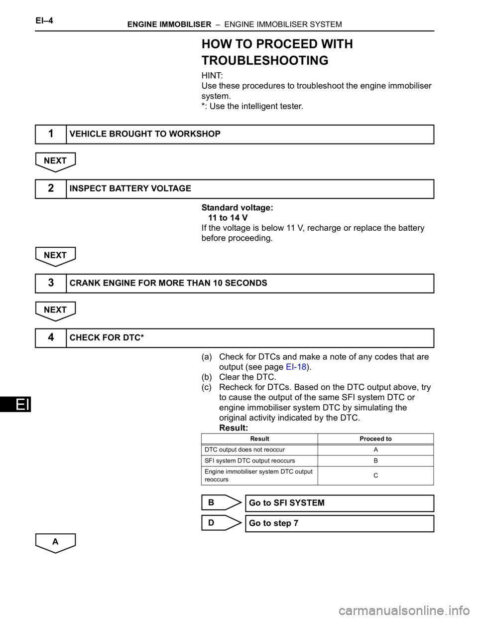
HOW TO PROCEED WITH
TROUBLESHOOTING
HINT:
Use these procedures to troubleshoot the engine immobiliser
system.
*: Use the intelligent tester.
NEXT
Standard voltage:
11 to 14 V
If the voltage is below 11 V, recharge or replace the battery
before proceeding.
NEXT
NEXT
(a) Check for DTCs and make a note of any codes that are
output (see page EI-18).
(b) Clear the DTC.
(c) Recheck for DTCs. Based on the DTC output above, try
to cause the output of the same SFI system DTC or
engine immobiliser system DTC by simulating the
original activity indicated by the DTC.
Result:
B
D
A
1VEHICLE BROUGHT TO WORKSHOP
2INSPECT BATTERY VOLTAGE
3CRANK ENGINE FOR MORE THAN 10 SECONDS
4CHECK FOR DTC*
Result Proceed to
DTC output does not reoccur A
SFI system DTC output reoccurs B
Engine immobiliser system DTC output
reoccursC
Go to SFI SYSTEM
Go to step 7