TOYOTA RAV4 2006 Service Repair Manual
Manufacturer: TOYOTA, Model Year: 2006,
Model line: RAV4,
Model: TOYOTA RAV4 2006
Pages: 2000, PDF Size: 45.84 MB
TOYOTA RAV4 2006 Service Repair Manual
RAV4 2006
TOYOTA
TOYOTA
https://www.carmanualsonline.info/img/14/57463/w960_57463-0.png
TOYOTA RAV4 2006 Service Repair Manual
Trending: etc, Ws atf, Install oil pan sub-assembly, Belt, Rele, rear entertainment, compression ratio
Page 411 of 2000
TW–4TIRE AND WHEEL – TIRE PRESSURE WARNING SYSTEM
TW
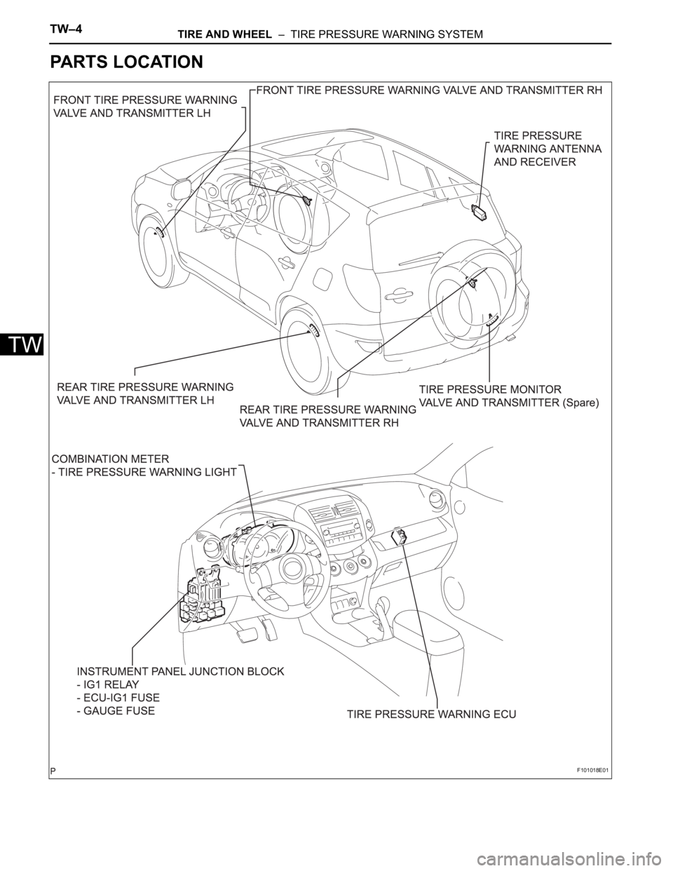
PARTS LOCATION
F101018E01
Page 412 of 2000
TIRE AND WHEEL – TIRE PRESSURE WARNING SYSTEMTW–5
TW
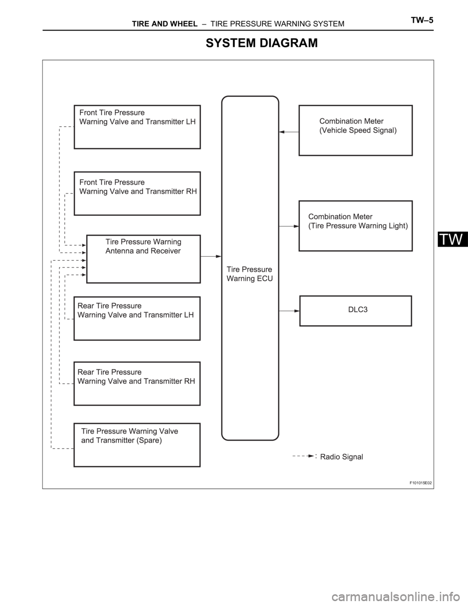
SYSTEM DIAGRAM
F101015E02
Page 413 of 2000
BC–4BRAKE CONTROL – VEHICLE STABILITY CONTROL SYSTEM
BC
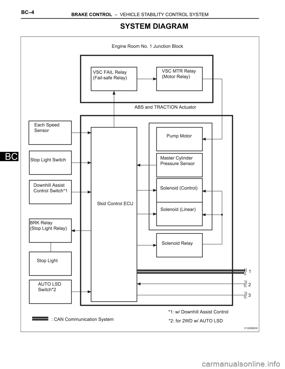
SYSTEM DIAGRAM
C132092E03
Page 414 of 2000
BRAKE CONTROL – VEHICLE STABILITY CONTROL SYSTEMBC–5
BC
C136077E01
Page 415 of 2000
BRAKE – BRAKE SYSTEMBR–3
BR
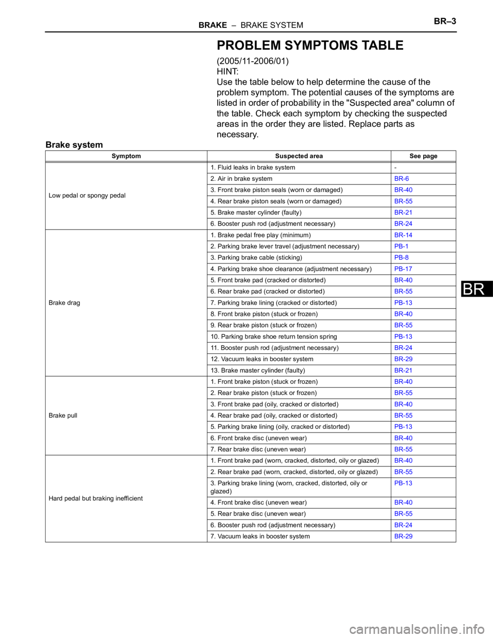
PROBLEM SYMPTOMS TABLE
(2005/11-2006/01)
HINT:
Use the table below to help determine the cause of the
problem symptom. The potential causes of the symptoms are
listed in order of probability in the "Suspected area" column of
the table. Check each symptom by checking the suspected
areas in the order they are listed. Replace parts as
necessary.
Brake system
Symptom Suspected area See page
Low pedal or spongy pedal1. Fluid leaks in brake system -
2. Air in brake systemBR-6
3. Front brake piston seals (worn or damaged)BR-40
4. Rear brake piston seals (worn or damaged)BR-55
5. Brake master cylinder (faulty)BR-21
6. Booster push rod (adjustment necessary)BR-24
Brake drag1. Brake pedal free play (minimum)BR-14
2. Parking brake lever travel (adjustment necessary)PB-1
3. Parking brake cable (sticking)PB-8
4. Parking brake shoe clearance (adjustment necessary)PB-17
5. Front brake pad (cracked or distorted)BR-40
6. Rear brake pad (cracked or distorted)BR-55
7. Parking brake lining (cracked or distorted)PB-13
8. Front brake piston (stuck or frozen)BR-40
9. Rear brake piston (stuck or frozen)BR-55
10. Parking brake shoe return tension springPB-13
11. Booster push rod (adjustment necessary)BR-24
12. Vacuum leaks in booster systemBR-29
13. Brake master cylinder (faulty)BR-21
Brake pull1. Front brake piston (stuck or frozen)BR-40
2. Rear brake piston (stuck or frozen)BR-55
3. Front brake pad (oily, cracked or distorted)BR-40
4. Rear brake pad (oily, cracked or distorted)BR-55
5. Parking brake lining (oily, cracked or distorted)PB-13
6. Front brake disc (uneven wear)BR-40
7. Rear brake disc (uneven wear)BR-55
Hard pedal but braking inefficient1. Front brake pad (worn, cracked, distorted, oily or glazed)BR-40
2. Rear brake pad (worn, cracked, distorted, oily or glazed)BR-55
3. Parking brake lining (worn, cracked, distorted, oily or
glazed)PB-13
4. Front brake disc (uneven wear)BR-40
5. Rear brake disc (uneven wear)BR-55
6. Booster push rod (adjustment necessary)BR-24
7. Vacuum leaks in booster systemBR-29
Page 416 of 2000
BR–4BRAKE – BRAKE SYSTEM
BR
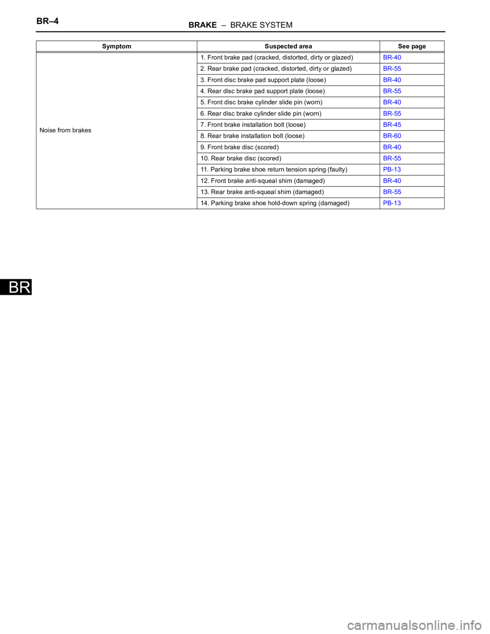
Noise from brakes1. Front brake pad (cracked, distorted, dirty or glazed)BR-40
2. Rear brake pad (cracked, distorted, dirty or glazed)BR-55
3. Front disc brake pad support plate (loose)BR-40
4. Rear disc brake pad support plate (loose)BR-55
5. Front disc brake cylinder slide pin (worn)BR-40
6. Rear disc brake cylinder slide pin (worn)BR-55
7. Front brake installation bolt (loose)BR-45
8. Rear brake installation bolt (loose)BR-60
9. Front brake disc (scored)BR-40
10. Rear brake disc (scored)BR-55
11. Parking brake shoe return tension spring (faulty)PB-13
12. Front brake anti-squeal shim (damaged)BR-40
13. Rear brake anti-squeal shim (damaged)BR-55
14. Parking brake shoe hold-down spring (damaged)PB-13 Symptom Suspected area See page
Page 417 of 2000
PARKING BRAKE – PARKING BRAKE LEVERPB–5
PB
REMOVAL
1. DISCONNECT CABLE FROM NEGATIVE BATTERY
TERMINAL
CAUTION:
Wait at least 90 seconds after disconnecting the
cable from the negative (-) battery terminal to
prevent airbag and seat belt pretensioner activation.
2. REMOVE REAR CONSOLE BOX SUB-ASSEMBLY
(a) Remove the rear console box (see page IP-16).
HINT:
Refer to the procedures from the removal of the No.
1 console upper panel garnish up until the removal
of the rear console box sub-assembly.
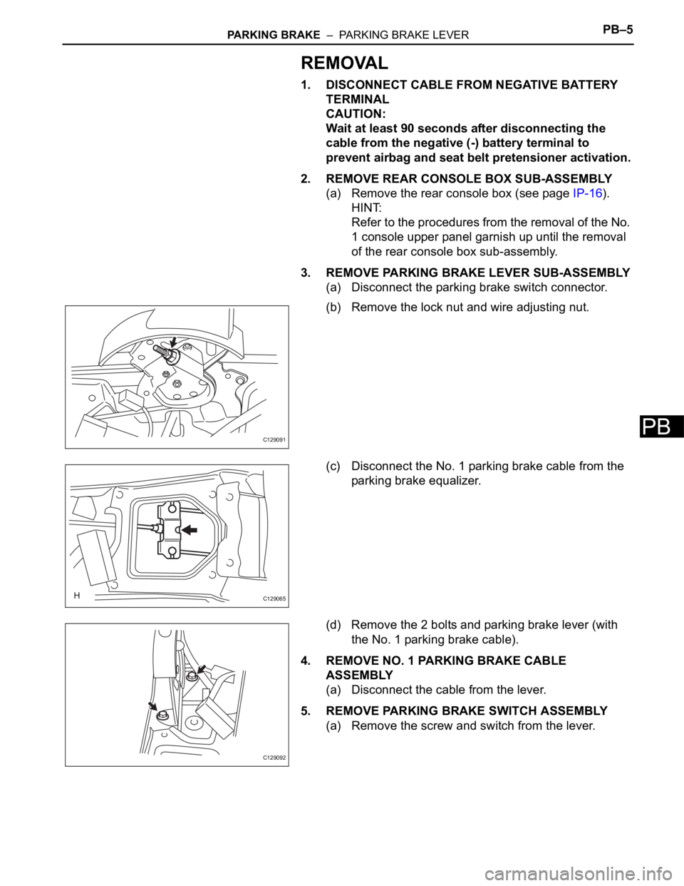
3. REMOVE PARKING BRAKE LEVER SUB-ASSEMBLY
(a) Disconnect the parking brake switch connector.
(b) Remove the lock nut and wire adjusting nut.
(c) Disconnect the No. 1 parking brake cable from the
parking brake equalizer.
(d) Remove the 2 bolts and parking brake lever (with
the No. 1 parking brake cable).
4. REMOVE NO. 1 PARKING BRAKE CABLE
ASSEMBLY
(a) Disconnect the cable from the lever.
5. REMOVE PARKING BRAKE SWITCH ASSEMBLY
(a) Remove the screw and switch from the lever.
C129091
C129065
C129092
Page 418 of 2000
PB–6PARKING BRAKE – PARKING BRAKE LEVER
PB
INSTALLATION
1. INSTALL PARKING BRAKE SWITCH ASSEMBLY
(a) Install the parking brake switch with the screw.
Torque: 0.88 N*m (9.0 kgf*cm, 7.8 in.*lbf)
2. INSTALL NO. 1 PARKING BRAKE CABLE ASSEMBLY
(a) Connect the cable to the lever.
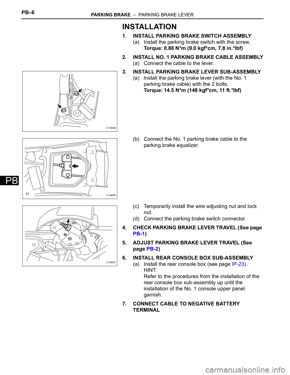
3. INSTALL PARKING BRAKE LEVER SUB-ASSEMBLY
(a) Install the parking brake lever (with the No. 1
parking brake cable) with the 2 bolts.
Torque: 14.5 N*m (148 kgf*cm, 11 ft.*lbf)
(b) Connect the No. 1 parking brake cable to the
parking brake equalizer.
(c) Temporarily install the wire adjusting nut and lock
nut.
(d) Connect the parking brake switch connector.
4. CHECK PARKING BRAKE LEVER TRAVEL (See page
PB-1)
5. ADJUST PARKING BRAKE LEVER TRAVEL (See
page PB-2)
6. INSTALL REAR CONSOLE BOX SUB-ASSEMBLY
(a) Install the rear console box (see page IP-23).
HINT:
Refer to the procedures from the installation of the
rear console box sub-assembly up until the
installation of the No. 1 console upper panel
garnish.
7. CONNECT CABLE TO NEGATIVE BATTERY
TERMINAL
C129092
C129065
C129091
Page 419 of 2000
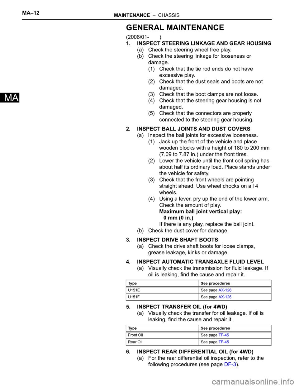
MA–12MAINTENANCE – CHASSIS
MA
GENERAL MAINTENANCE
(2006/01- )
1. INSPECT STEERING LINKAGE AND GEAR HOUSING
(a) Check the steering wheel free play.
(b) Check the steering linkage for looseness or
damage.
(1) Check that the tie rod ends do not have
excessive play.
(2) Check that the dust seals and boots are not
damaged.
(3) Check that the boot clamps are not loose.
(4) Check that the steering gear housing is not
damaged.
(5) Check that the connectors are properly
connected to the steering gear housing.
2. INSPECT BALL JOINTS AND DUST COVERS
(a) Inspect the ball joints for excessive looseness.
(1) Jack up the front of the vehicle and place
wooden blocks with a height of 180 to 200 mm
(7.09 to 7.87 in.) under the front tires.
(2) Lower the vehicle until the front coil spring has
about half its ordinary load. Place stands under
the vehicle for safety.
(3) Check that the front wheels are pointing
straight ahead. Use wheel chocks on all 4
wheels.
(4) Using a lever, pry up the end of the lower arm.
Check the amount of play.
Maximum ball joint vertical play:
0 mm (0 in.)
If there is any play, replace the ball joint.
(b) Check the dust cover for damage.
3. INSPECT DRIVE SHAFT BOOTS
(a) Check the drive shaft boots for loose clamps,
grease leakage, kinks or damage.
4. INSPECT AUTOMATIC TRANSAXLE FLUID LEVEL
(a) Visually check the transmission for fluid leakage. If
oil is leaking, find the cause and repair it.
5. INSPECT TRANSFER OIL (for 4WD)
(a) Visually check the transfer for oil leakage. If oil is
leaking, find the cause and repair it.
6. INSPECT REAR DIFFERENTIAL OIL (for 4WD)
(a) For the rear differential oil inspection, refer to the
following procedures (see page DF-3).
Type See procedures
U151E See page AX-126
U151F See page AX-126
Type See procedures
Front Oil See page TF-45
Rear Oil See page TF-45
Page 420 of 2000
MAINTENANCE – CHASSISMA–13
MA
7. ROTATE TIRES (See page TW-1)
Trending: transaxle, Lu-17, set clock, open gas tank, pcv valve, oil temperature, fuel pump circuit
