TOYOTA RAV4 2006 Service Repair Manual
Manufacturer: TOYOTA, Model Year: 2006,
Model line: RAV4,
Model: TOYOTA RAV4 2006
Pages: 2000, PDF Size: 45.84 MB
TOYOTA RAV4 2006 Service Repair Manual
RAV4 2006
TOYOTA
TOYOTA
https://www.carmanualsonline.info/img/14/57463/w960_57463-0.png
TOYOTA RAV4 2006 Service Repair Manual
Trending: washer fluid, wiper blades, battery location, heater, roof, Vsc, engine oil
Page 391 of 2000
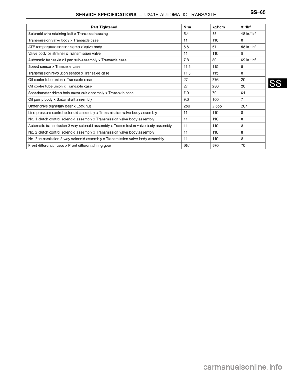
SERVICE SPECIFICATIONS – U241E AUTOMATIC TRANSAXLESS–65
SS
Solenoid wire retaining bolt x Transaxle housing 5.4 55 48 in.*lbf
Transmission valve body x Transaxle case 11 110 8
ATF temperature sensor clamp x Valve body 6.6 67 58 in.*lbf
Valve body oil strainer x Transmission valve 11 110 8
Automatic transaxle oil pan sub-assembly x Transaxle case 7.8 80 69 in.*lbf
Speed sensor x Transaxle case 11.3 115 8
Transmission revolution sensor x Transaxle case 11.3 115 8
Oil cooler tube union x Transaxle case 27 276 20
Oil cooler tube union x Transaxle case 27 280 20
Speedometer driven hole cover sub-assembly x Transaxle case 7.0 7061
Oil pump body x Stator shaft assembly 9.8 100 7
Under drive planetary gear x Lock nut 280 2,855 207
Line pressure control solenoid assembly x Transmission valve body assembly 11 110 8
No. 1 clutch control solenoid assembly x Transmission valve body assembly 11 110 8
Automatic transmission 3 way solenoid assembly x Transmission valve body assembly 11 110 8
No. 2 clutch control solenoid assembly x Transmission valve body assembly 11 110 8
No. 2 transmission 3 way solenoid assembly x Transmission valve body assembly 11 110 8
Front differential case x Front differential ring gear 95.1 970 70Part Tightened N*m kgf*cm ft.*lbf
Page 392 of 2000
SERVICE SPECIFICATIONS – GF1A TRANSFERSS–69
SS
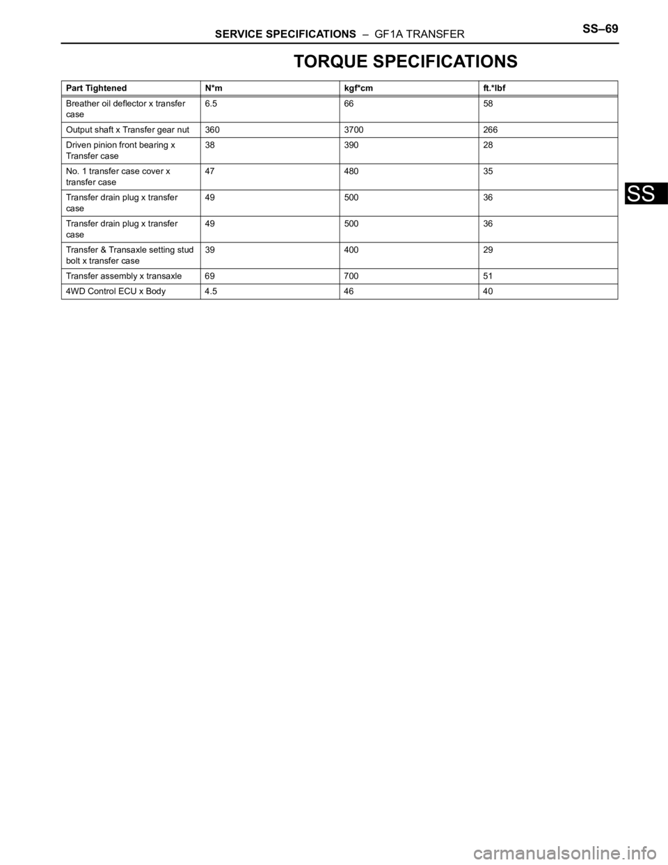
TORQUE SPECIFICATIONS
Part Tightened N*m kgf*cm ft.*lbf
Breather oil deflector x transfer
case6.5 66 58
Output shaft x Transfer gear nut 360 3700 266
Driven pinion front bearing x
Transfer case38 390 28
No. 1 transfer case cover x
transfer case47 480 35
Transfer drain plug x transfer
case49 500 36
Transfer drain plug x transfer
case49 500 36
Transfer & Transaxle setting stud
bolt x transfer case39 400 29
Transfer assembly x transaxle 69 700 51
4WD Control ECU x Body 4.5 46 40
Page 393 of 2000
SS–72SERVICE SPECIFICATIONS – DRIVE SHAFT
SS
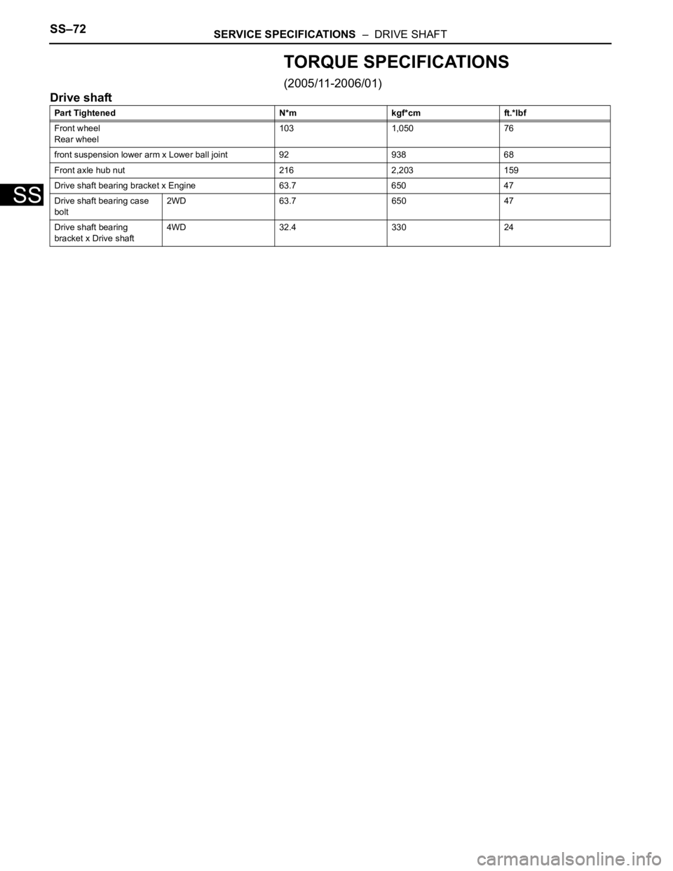
TORQUE SPECIFICATIONS
(2005/11-2006/01)
Drive shaft
Part Tightened N*m kgf*cm ft.*lbf
Front wheel
Rear wheel103 1,050 76
front suspension lower arm x Lower ball joint 92 938 68
Front axle hub nut 216 2,203 159
Drive shaft bearing bracket x Engine 63.7 650 47
Drive shaft bearing case
bolt2WD 63.7 650 47
Drive shaft bearing
bracket x Drive shaft4WD 32.4 330 24
Page 394 of 2000
SERVICE SPECIFICATIONS – DRIVE SHAFTSS–73
SS
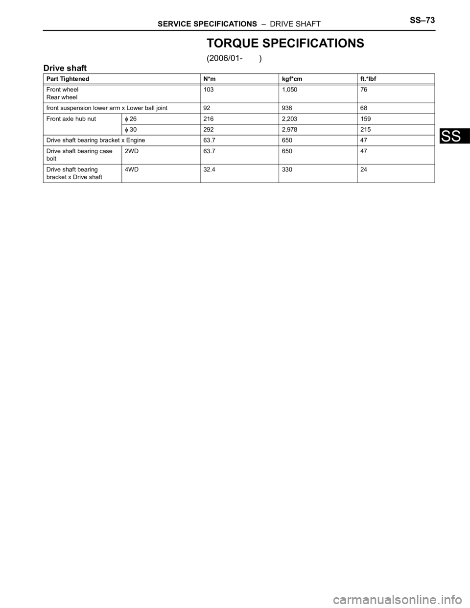
TORQUE SPECIFICATIONS
(2006/01- )
Drive shaft
Part Tightened N*m kgf*cm ft.*lbf
Front wheel
Rear wheel103 1,050 76
front suspension lower arm x Lower ball joint 92 938 68
Front axle hub nut
26 216 2,203 159
30 292 2,978 215
Drive shaft bearing bracket x Engine 63.7 650 47
Drive shaft bearing case
bolt2WD 63.7 650 47
Drive shaft bearing
bracket x Drive shaft4WD 32.4 330 24
Page 395 of 2000
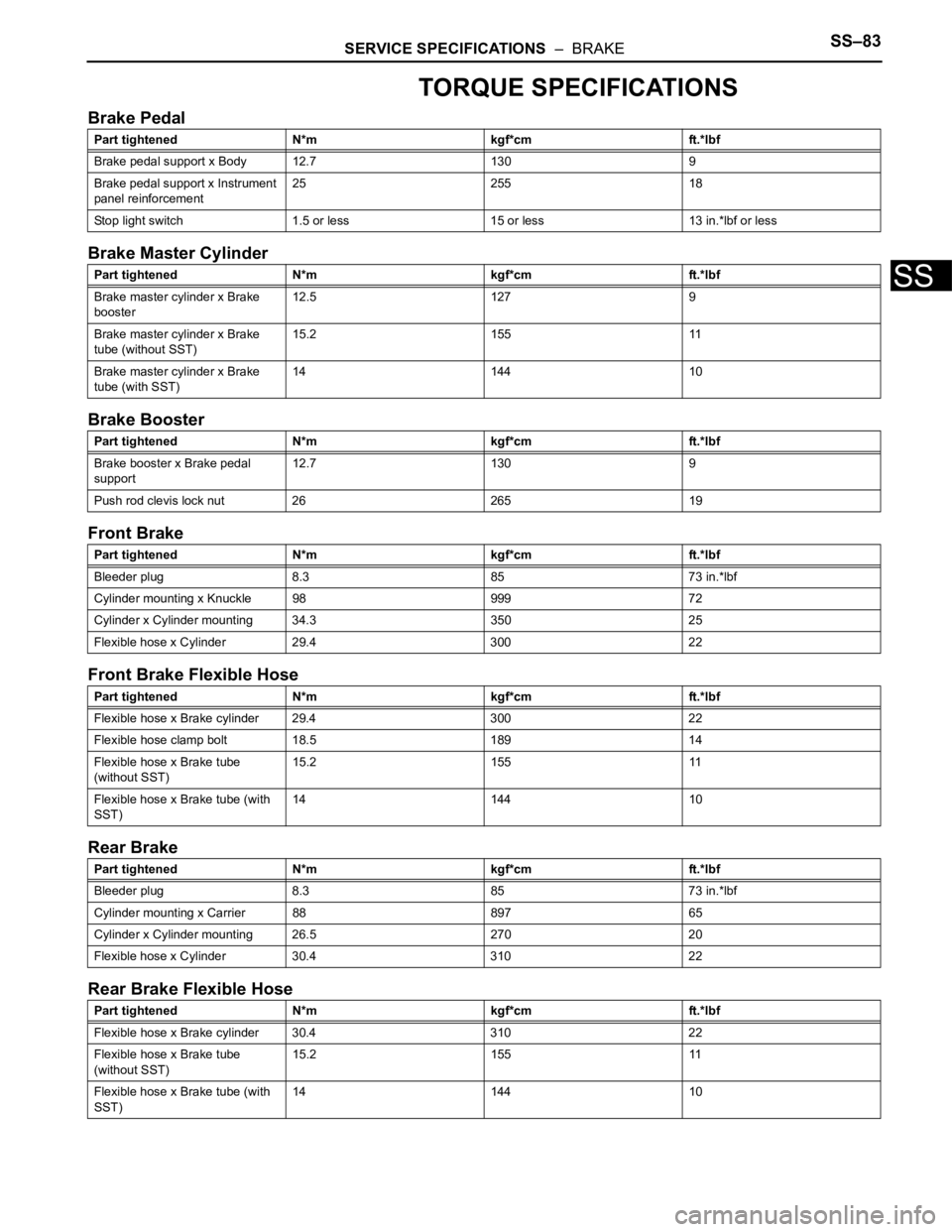
SERVICE SPECIFICATIONS – BRAKESS–83
SS
TORQUE SPECIFICATIONS
Brake Pedal
Brake Master Cylinder
Brake Booster
Front Brake
Front Brake Flexible Hose
Rear Brake
Rear Brake Flexible Hose
Part tightened N*m kgf*cm ft.*lbf
Brake pedal support x Body 12.7 130 9
Brake pedal support x Instrument
panel reinforcement25 255 18
Stop light switch 1.5 or less 15 or less 13 in.*lbf or less
Part tightened N*m kgf*cm ft.*lbf
Brake master cylinder x Brake
booster12.5 127 9
Brake master cylinder x Brake
tube (without SST)15.2 155 11
Brake master cylinder x Brake
tube (with SST)14 144 10
Part tightened N*m kgf*cm ft.*lbf
Brake booster x Brake pedal
support12.7 130 9
Push rod clevis lock nut 26 265 19
Part tightened N*m kgf*cm ft.*lbf
Bleeder plug 8.3 85 73 in.*lbf
Cylinder mounting x Knuckle 98 999 72
Cylinder x Cylinder mounting 34.3 350 25
Flexible hose x Cylinder 29.4 300 22
Part tightened N*m kgf*cm ft.*lbf
Flexible hose x Brake cylinder 29.4 300 22
Flexible hose clamp bolt 18.5 189 14
Flexible hose x Brake tube
(without SST)15.2 155 11
Flexible hose x Brake tube (with
SST)14 144 10
Part tightened N*m kgf*cm ft.*lbf
Bleeder plug 8.3 85 73 in.*lbf
Cylinder mounting x Carrier 88 897 65
Cylinder x Cylinder mounting 26.5 270 20
Flexible hose x Cylinder 30.4 310 22
Part tightened N*m kgf*cm ft.*lbf
Flexible hose x Brake cylinder 30.4 310 22
Flexible hose x Brake tube
(without SST)15.2 155 11
Flexible hose x Brake tube (with
SST)14 144 10
Page 396 of 2000
PROPELLER SHAFT – PROPELLER SHAFT ASSEMBLYPR–5
PR
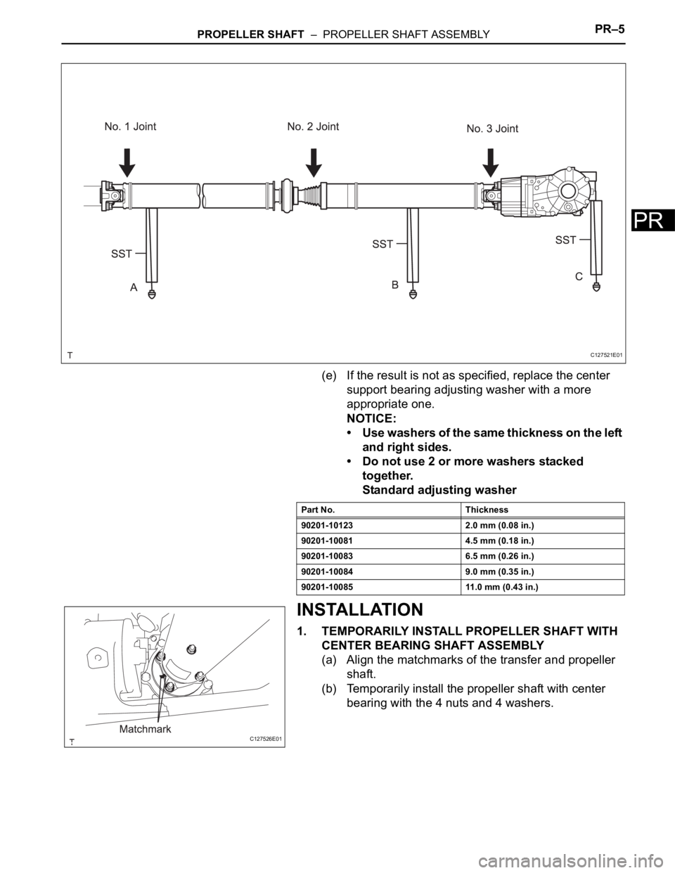
(e) If the result is not as specified, replace the center
support bearing adjusting washer with a more
appropriate one.
NOTICE:
• Use washers of the same thickness on the left
and right sides.
• Do not use 2 or more washers stacked
together.
Standard adjusting washer
INSTALLATION
1. TEMPORARILY INSTALL PROPELLER SHAFT WITH
CENTER BEARING SHAFT ASSEMBLY
(a) Align the matchmarks of the transfer and propeller
shaft.
(b) Temporarily install the propeller shaft with center
bearing with the 4 nuts and 4 washers.
C127521E01
Part No. Thickness
90201-10123 2.0 mm (0.08 in.)
90201-10081 4.5 mm (0.18 in.)
90201-10083 6.5 mm (0.26 in.)
90201-10084 9.0 mm (0.35 in.)
90201-10085 11.0 mm (0.43 in.)
C127526E01
Page 397 of 2000
PR–6PROPELLER SHAFT – PROPELLER SHAFT ASSEMBLY
PR
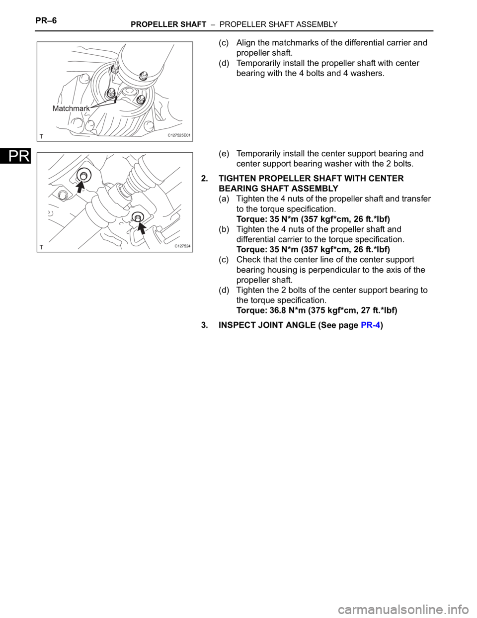
(c) Align the matchmarks of the differential carrier and
propeller shaft.
(d) Temporarily install the propeller shaft with center
bearing with the 4 bolts and 4 washers.
(e) Temporarily install the center support bearing and
center support bearing washer with the 2 bolts.
2. TIGHTEN PROPELLER SHAFT WITH CENTER
BEARING SHAFT ASSEMBLY
(a) Tighten the 4 nuts of the propeller shaft and transfer
to the torque specification.
Torque: 35 N*m (357 kgf*cm, 26 ft.*lbf)
(b) Tighten the 4 nuts of the propeller shaft and
differential carrier to the torque specification.
Torque: 35 N*m (357 kgf*cm, 26 ft.*lbf)
(c) Check that the center line of the center support
bearing housing is perpendicular to the axis of the
propeller shaft.
(d) Tighten the 2 bolts of the center support bearing to
the torque specification.
Torque: 36.8 N*m (375 kgf*cm, 27 ft.*lbf)
3. INSPECT JOINT ANGLE (See page PR-4)
C127525E01
C127524
Page 398 of 2000
DS–4DRIVE SHAFT – FRONT DRIVE SHAFT ASSEMBLY (for 2WD)
DS
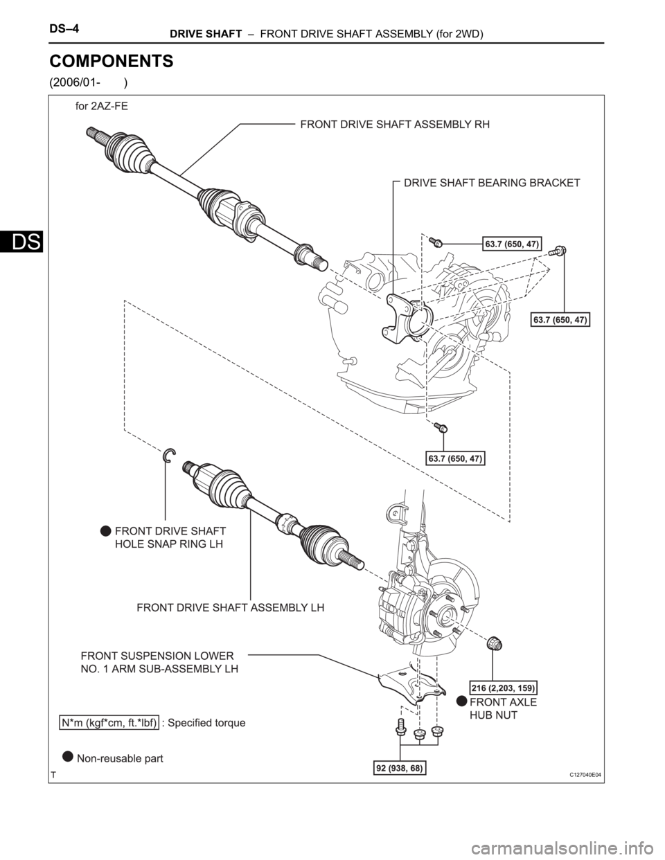
COMPONENTS
(2006/01- )
C127040E04
Page 399 of 2000
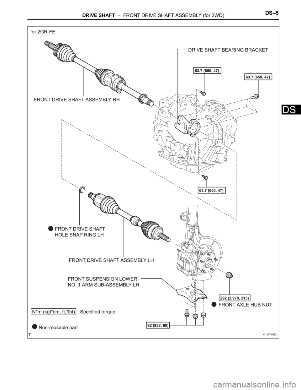
DRIVE SHAFT – FRONT DRIVE SHAFT ASSEMBLY (for 2WD)DS–5
DS
C137744E01
Page 400 of 2000
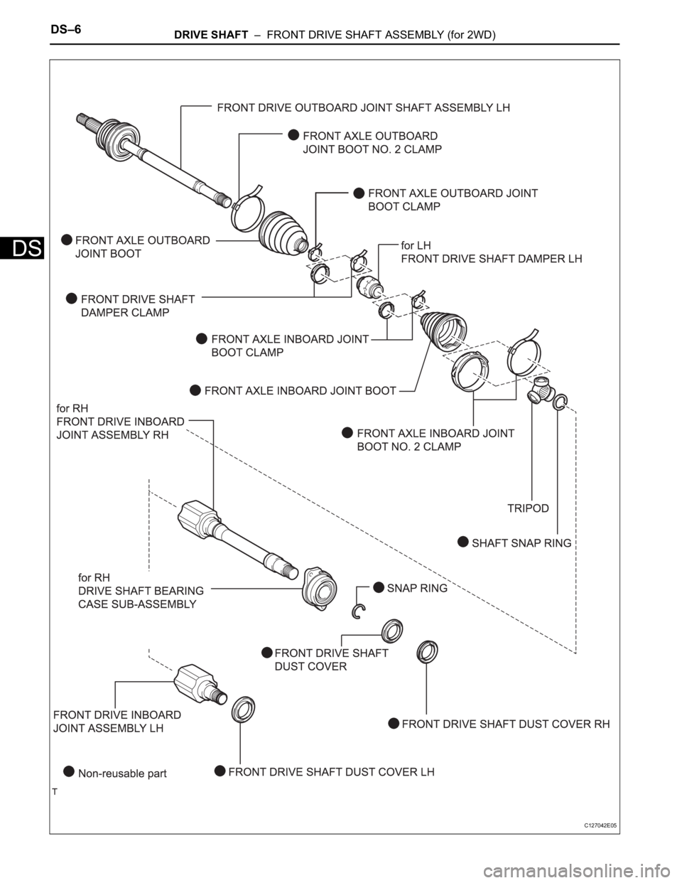
DS–6DRIVE SHAFT – FRONT DRIVE SHAFT ASSEMBLY (for 2WD)
DS
C127042E05
Trending: parking brake, drain, heater, hood, ECO mode, wiper blades, oil temperature

