TOYOTA SIENNA 2007 Service Repair Manual
Manufacturer: TOYOTA, Model Year: 2007, Model line: SIENNA, Model: TOYOTA SIENNA 2007Pages: 3000, PDF Size: 52.26 MB
Page 1851 of 3000
AX–156U151F AUTOMATIC TRANSAXLE – TRANSMISSION CONTROL CABLE ASSEMBLY
AX
ADJUSTMENT
1. INSPECT SHIFT LEVER POSITION
(a) When shifting from P to R position only with ignition
switch ON and brake pedal, make sure that the
shifting lever moves smoothly and can be
moderately operated.
(b) When starting engine, make sure that the vehicle
moves forward when shifting from N to D position
and moves rearward when shifting to R position.
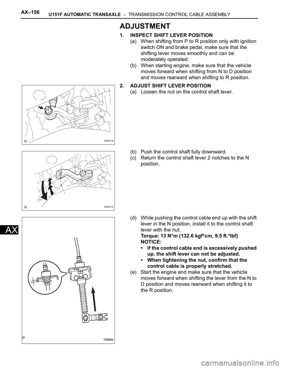
2. ADJUST SHIFT LEVER POSITION
(a) Loosen the nut on the control shaft lever.
(b) Push the control shaft fully downward.
(c) Return the control shaft lever 2 notches to the N
position.
(d) While pushing the control cable end up with the shift
lever in the N position, install it to the control shaft
lever with the nut.
Torque: 13 N*m (132.6 kgf*cm, 9.5 ft.*lbf)
NOTICE:
• If the control cable end is excessively pushed
up, the shift lever can not be adjusted.
• When tightening the nut, confirm that the
control cable is properly stretched.
(e) Start the engine and make sure that the vehicle
moves forward when shifting the lever from the N to
D position and moves rearward when shifting it to
the R position.
D025118
D025119
C098998
Page 1852 of 3000
U151F AUTOMATIC TRANSAXLE – TRANSMISSION CONTROL CABLE ASSEMBLYAX–157
AX
INSTALLATION
1. INSTALL TRANSMISSION CONTROL CABLE
ASSEMBLY
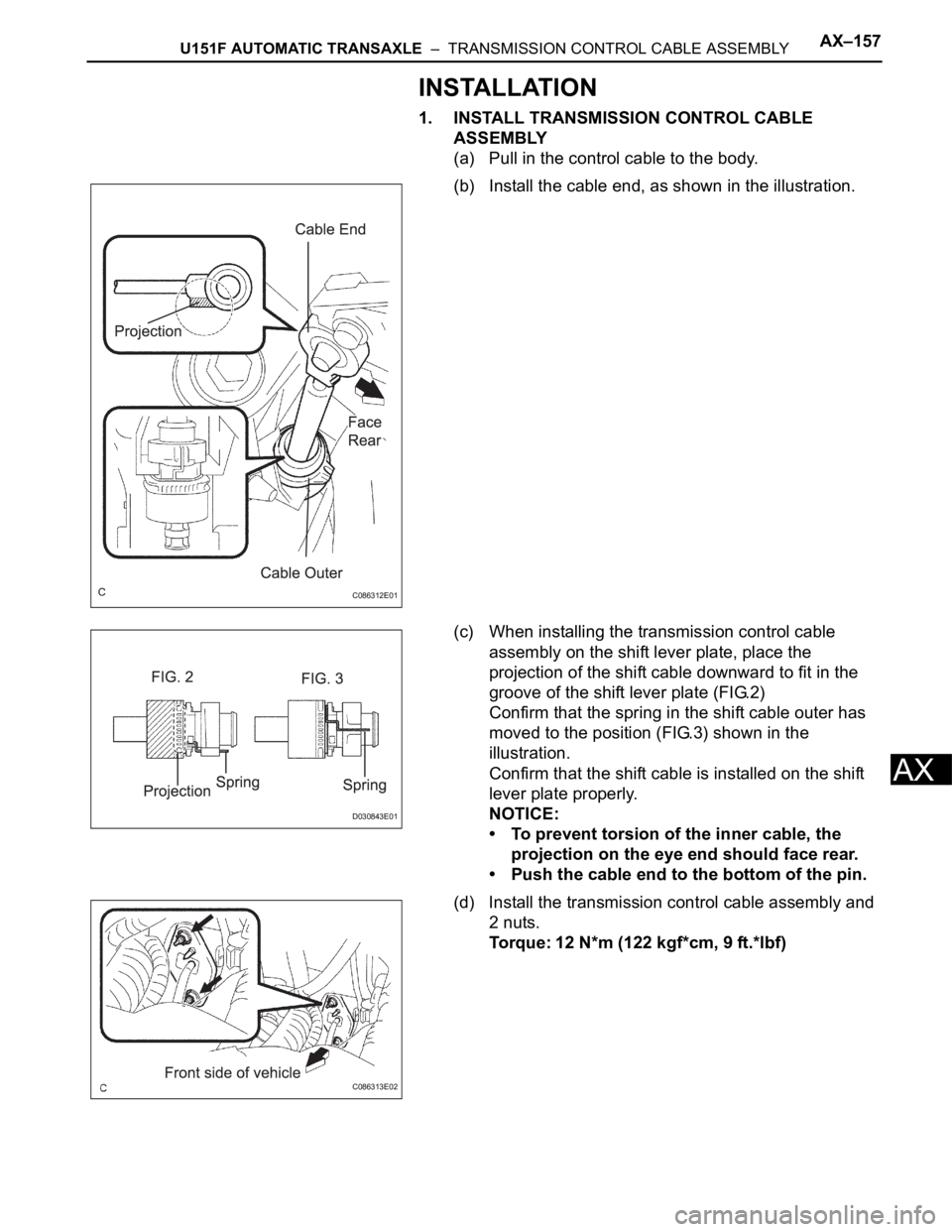
(a) Pull in the control cable to the body.
(b) Install the cable end, as shown in the illustration.
(c) When installing the transmission control cable
assembly on the shift lever plate, place the
projection of the shift cable downward to fit in the
groove of the shift lever plate (FIG.2)
Confirm that the spring in the shift cable outer has
moved to the position (FIG.3) shown in the
illustration.
Confirm that the shift cable is installed on the shift
lever plate properly.
NOTICE:
• To prevent torsion of the inner cable, the
projection on the eye end should face rear.
• Push the cable end to the bottom of the pin.
(d) Install the transmission control cable assembly and
2 nuts.
Torque: 12 N*m (122 kgf*cm, 9 ft.*lbf)
C086312E01
D030843E01
C086313E02
Page 1853 of 3000
AX–158U151F AUTOMATIC TRANSAXLE – TRANSMISSION CONTROL CABLE ASSEMBLY
AX
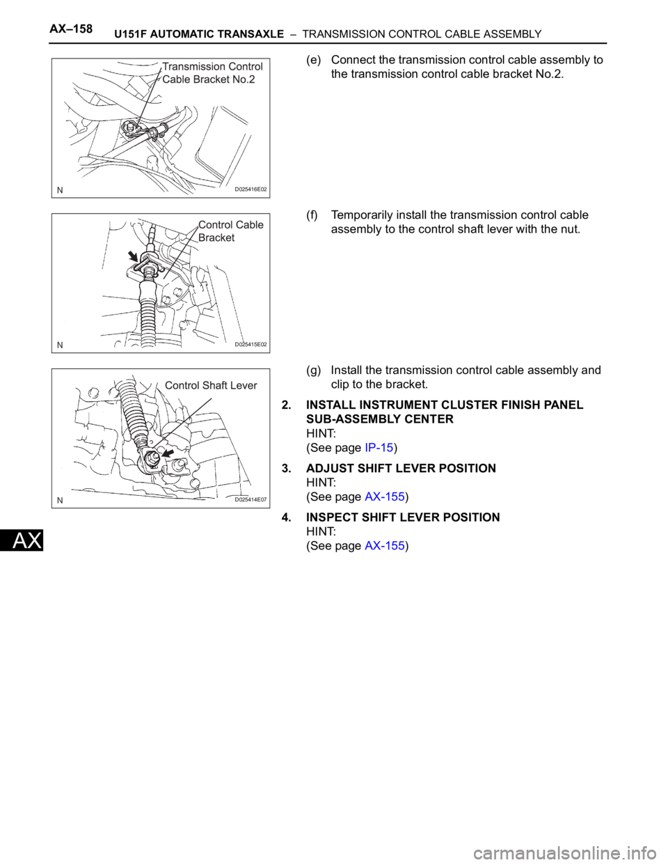
(e) Connect the transmission control cable assembly to
the transmission control cable bracket No.2.
(f) Temporarily install the transmission control cable
assembly to the control shaft lever with the nut.
(g) Install the transmission control cable assembly and
clip to the bracket.
2. INSTALL INSTRUMENT CLUSTER FINISH PANEL
SUB-ASSEMBLY CENTER
HINT:
(See page IP-15)
3. ADJUST SHIFT LEVER POSITION
HINT:
(See page AX-155)
4. INSPECT SHIFT LEVER POSITION
HINT:
(See page AX-155)
D025416E02
D025415E02
D025414E07
Page 1854 of 3000
AX–32U151F AUTOMATIC TRANSAXLE – AUTOMATIC TRANSAXLE SYSTEM
AX
DTC CHECK / CLEAR
1. DTC CHECK (NORMAL MODE)
NOTICE:
When the diagnostic system is switched from the
normal mode to the check mode, all the DTCs and
freeze frame data recorded in the normal mode will
be erased. So before switching modes, always check
the DTCs and freeze frame data, and note them
down.
(a) Checking DTCs using the OBD II scan tool or
intelligent tester.
(1) Turn the ignition switch off.
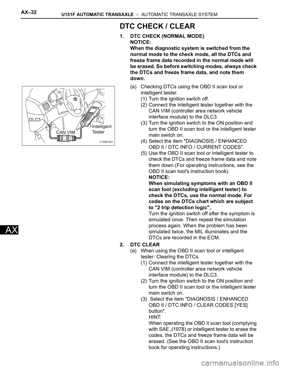
(2) Connect the intelligent tester together with the
CAN VIM (controller area network vehicle
interface module) to the DLC3.
(3) Turn the ignition switch to the ON position and
turn the OBD II scan tool or the intelligent tester
main switch on.
(4) Select the item "DIAGNOSIS / ENHANCED
OBD II / DTC INFO / CURRENT CODES".
(5) Use the OBD II scan tool or intelligent tester to
check the DTCs and freeze frame data and note
them down (For operating instructions, see the
OBD II scan tool's instruction book).
NOTICE:
When simulating symptoms with an OBD II
scan tool (excluding intelligent tester) to
check the DTCs, use the normal mode. For
codes on the DTCs chart which are subject
to "2 trip detection logic",
Turn the ignition switch off after the symptom is
simulated once. Then repeat the simulation
process again. When the problem has been
simulated twice, the MIL illuminates and the
DTCs are recorded in the ECM.
2. DTC CLEAR
(a) When using the OBD II scan tool or intelligent
tester: Clearing the DTCs.
(1) Connect the intelligent tester together with the
CAN VIM (controller area network vehicle
interface module) to the DLC3.
(2) Turn the ignition switch to the ON position and
turn the OBD II scan tool or the intelligent tester
main switch on.
(3) Select the item "DIAGNOSIS / ENHANCED
OBD II / DTC INFO / CLEAR CODES [YES]
button".
HINT:
When operating the OBD II scan tool (complying
with SAE J1978) or intelligent tester to erase the
codes, the DTCs and freeze frame data will be
erased. (See the OBD II scan tool's instruction
book for operating instructions.)
C159873E01
Page 1855 of 3000

U151F AUTOMATIC TRANSAXLE – AUTOMATIC TRANSAXLE SYSTEMAX–33
AX
(b) When not using the OBD II scan tool or intelligent
tester: Clearing the DTCs.
(1) Disconnect the battery terminal or remove the
EFI and ETCS fuses from the engine room J/B
for 60 seconds or more. However, if you
disconnect the battery terminal, perform do the
"INITIALIZE" procedure.
Page 1856 of 3000
U151F AUTOMATIC TRANSAXLE – AUTOMATIC TRANSAXLE UNITAX–181
AX
DISASSEMBLY
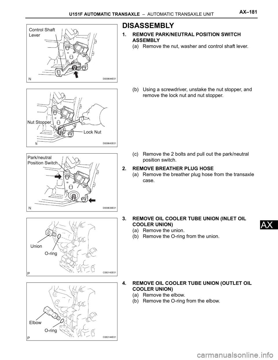
1. REMOVE PARK/NEUTRAL POSITION SWITCH
ASSEMBLY
(a) Remove the nut, washer and control shaft lever.
(b) Using a screwdriver, unstake the nut stopper, and
remove the lock nut and nut stopper.
(c) Remove the 2 bolts and pull out the park/neutral
position switch.
2. REMOVE BREATHER PLUG HOSE
(a) Remove the breather plug hose from the transaxle
case.
3. REMOVE OIL COOLER TUBE UNION (INLET OIL
COOLER UNION)
(a) Remove the union.
(b) Remove the O-ring from the union.
4. REMOVE OIL COOLER TUBE UNION (OUTLET OIL
COOLER UNION)
(a) Remove the elbow.
(b) Remove the O-ring from the elbow.
D009644E01
D009643E01
D009639E01
C083143E01
C083144E01
Page 1857 of 3000
AX–182U151F AUTOMATIC TRANSAXLE – AUTOMATIC TRANSAXLE UNIT
AX
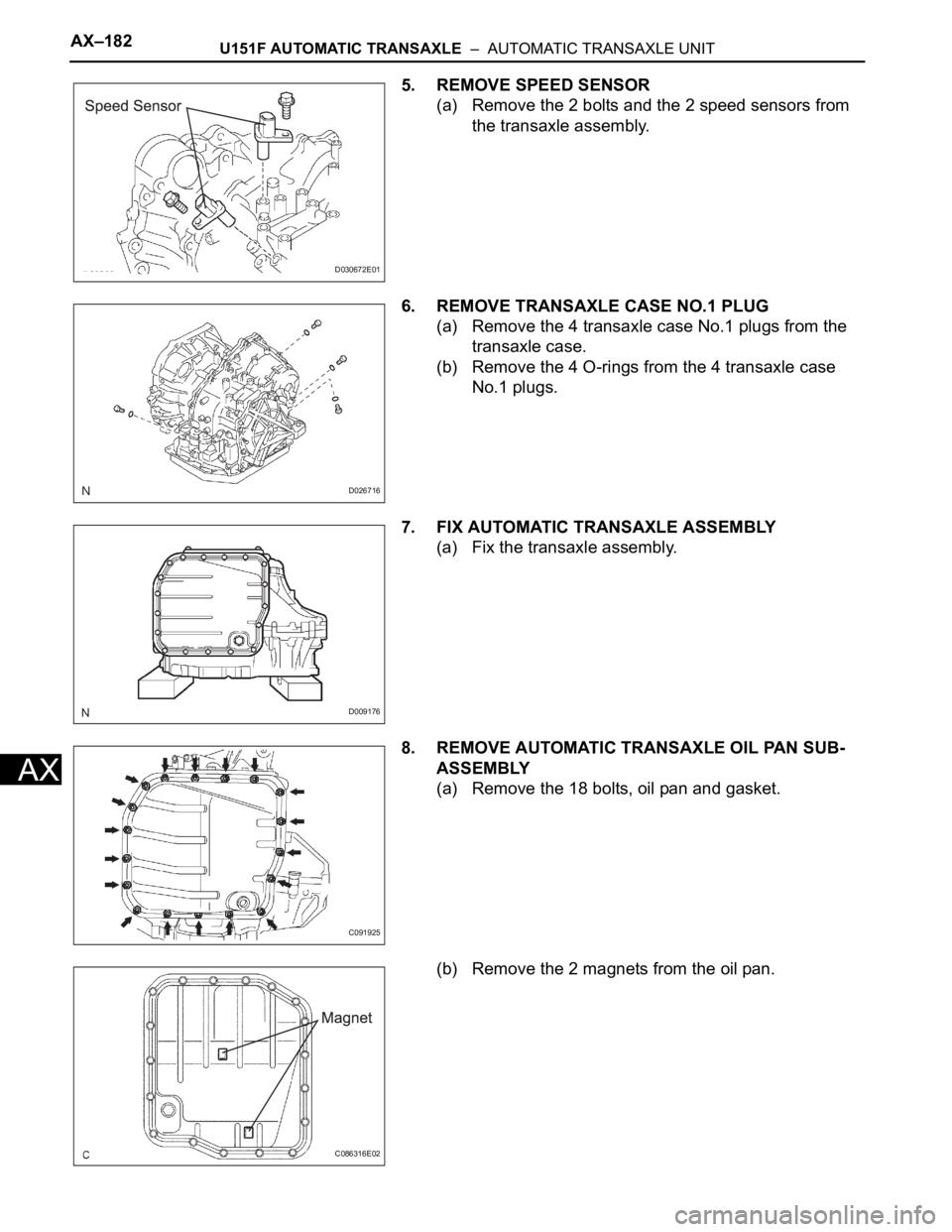
5. REMOVE SPEED SENSOR
(a) Remove the 2 bolts and the 2 speed sensors from
the transaxle assembly.
6. REMOVE TRANSAXLE CASE NO.1 PLUG
(a) Remove the 4 transaxle case No.1 plugs from the
transaxle case.
(b) Remove the 4 O-rings from the 4 transaxle case
No.1 plugs.
7. FIX AUTOMATIC TRANSAXLE ASSEMBLY
(a) Fix the transaxle assembly.
8. REMOVE AUTOMATIC TRANSAXLE OIL PAN SUB-
ASSEMBLY
(a) Remove the 18 bolts, oil pan and gasket.
(b) Remove the 2 magnets from the oil pan.
D030672E01
D026716
D009176
C091925
C086316E02
Page 1858 of 3000
U151F AUTOMATIC TRANSAXLE – AUTOMATIC TRANSAXLE UNITAX–183
AX
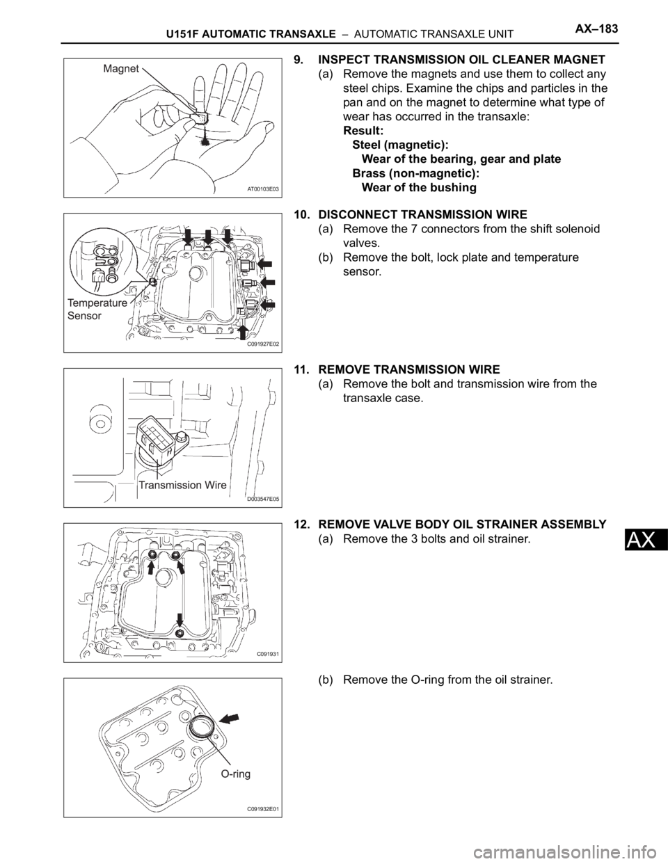
9. INSPECT TRANSMISSION OIL CLEANER MAGNET
(a) Remove the magnets and use them to collect any
steel chips. Examine the chips and particles in the
pan and on the magnet to determine what type of
wear has occurred in the transaxle:
Result:
Steel (magnetic):
Wear of the bearing, gear and plate
Brass (non-magnetic):
Wear of the bushing
10. DISCONNECT TRANSMISSION WIRE
(a) Remove the 7 connectors from the shift solenoid
valves.
(b) Remove the bolt, lock plate and temperature
sensor.
11. REMOVE TRANSMISSION WIRE
(a) Remove the bolt and transmission wire from the
transaxle case.
12. REMOVE VALVE BODY OIL STRAINER ASSEMBLY
(a) Remove the 3 bolts and oil strainer.
(b) Remove the O-ring from the oil strainer.
AT00103E03
C091927E02
D003547E05
C091931
C091932E01
Page 1859 of 3000
AX–184U151F AUTOMATIC TRANSAXLE – AUTOMATIC TRANSAXLE UNIT
AX
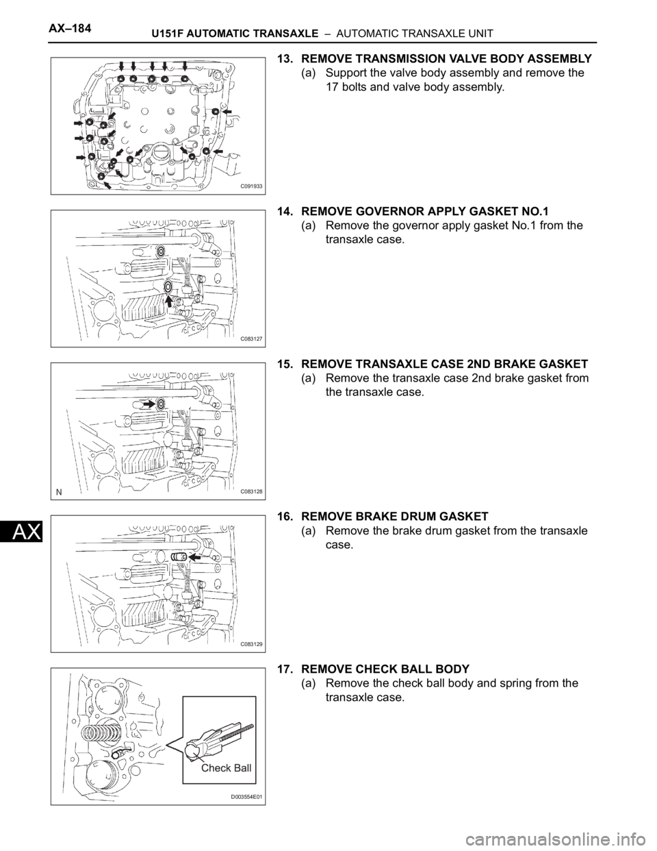
13. REMOVE TRANSMISSION VALVE BODY ASSEMBLY
(a) Support the valve body assembly and remove the
17 bolts and valve body assembly.
14. REMOVE GOVERNOR APPLY GASKET NO.1
(a) Remove the governor apply gasket No.1 from the
transaxle case.
15. REMOVE TRANSAXLE CASE 2ND BRAKE GASKET
(a) Remove the transaxle case 2nd brake gasket from
the transaxle case.
16. REMOVE BRAKE DRUM GASKET
(a) Remove the brake drum gasket from the transaxle
case.
17. REMOVE CHECK BALL BODY
(a) Remove the check ball body and spring from the
transaxle case.
C091933
C083127
C083128
C083129
D003554E01
Page 1860 of 3000
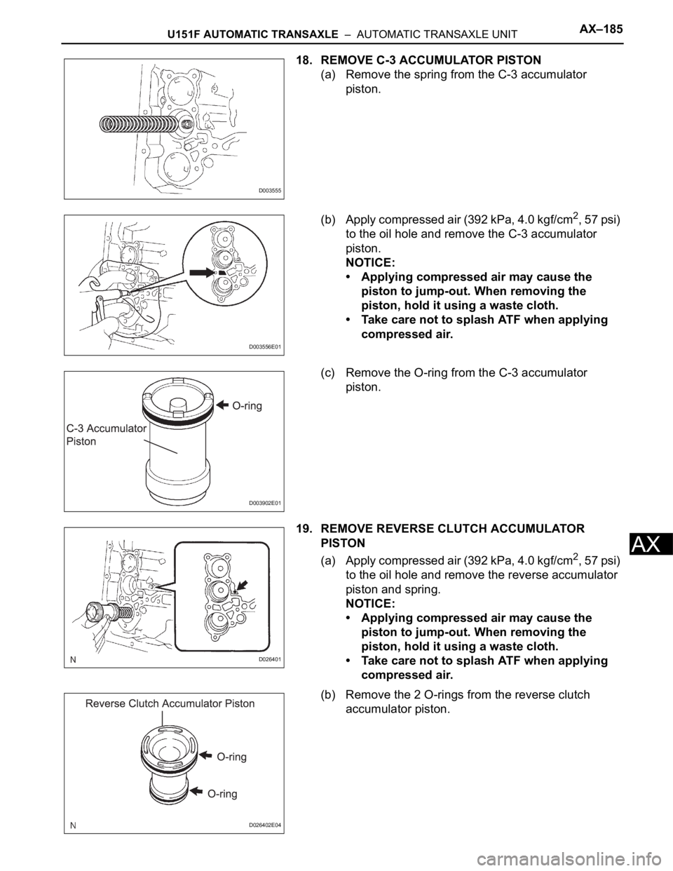
U151F AUTOMATIC TRANSAXLE – AUTOMATIC TRANSAXLE UNITAX–185
AX
18. REMOVE C-3 ACCUMULATOR PISTON
(a) Remove the spring from the C-3 accumulator
piston.
(b) Apply compressed air (392 kPa, 4.0 kgf/cm
2, 57 psi)
to the oil hole and remove the C-3 accumulator
piston.
NOTICE:
• Applying compressed air may cause the
piston to jump-out. When removing the
piston, hold it using a waste cloth.
• Take care not to splash ATF when applying
compressed air.
(c) Remove the O-ring from the C-3 accumulator
piston.
19. REMOVE REVERSE CLUTCH ACCUMULATOR
PISTON
(a) Apply compressed air (392 kPa, 4.0 kgf/cm
2, 57 psi)
to the oil hole and remove the reverse accumulator
piston and spring.
NOTICE:
• Applying compressed air may cause the
piston to jump-out. When removing the
piston, hold it using a waste cloth.
• Take care not to splash ATF when applying
compressed air.
(b) Remove the 2 O-rings from the reverse clutch
accumulator piston.
D003555
D003556E01
D003902E01
D026401
D026402E04