TOYOTA SIENNA 2007 Service Repair Manual
Manufacturer: TOYOTA, Model Year: 2007, Model line: SIENNA, Model: TOYOTA SIENNA 2007Pages: 3000, PDF Size: 52.26 MB
Page 181 of 3000
BRAKE CONTROL – ANTI-LOCK BRAKE SYSTEMBC–5
BC
• After the ABS warning light goes off and if
vehicle speed exceeds 50 mph (80 km/h), the
signal check code will be stored again.
Decelerate or stop the vehicle before the
speed reaches 50 mph (80 km/h).
• If the signal check has not been completed,
the ABS warning light blinks while driving
and the ABS system does not operate.
HINT:
When the signal check has been completed, the
ABS warning light goes off while driving and blinks
in the Test Mode pattern while stationary.
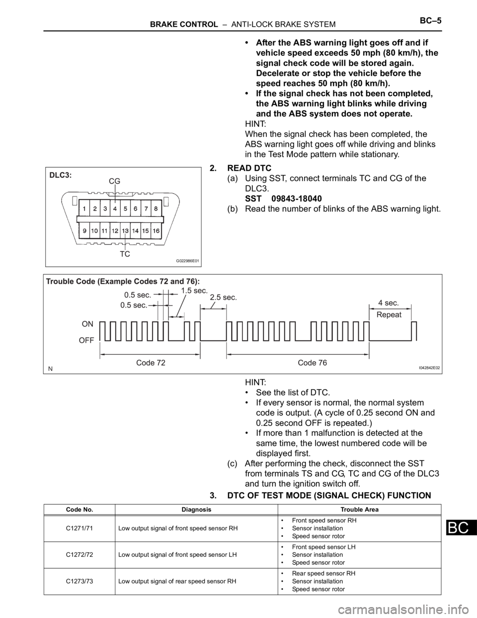
2. READ DTC
(a) Using SST, connect terminals TC and CG of the
DLC3.
SST 09843-18040
(b) Read the number of blinks of the ABS warning light.
HINT:
• See the list of DTC.
• If every sensor is normal, the normal system
code is output. (A cycle of 0.25 second ON and
0.25 second OFF is repeated.)
• If more than 1 malfunction is detected at the
same time, the lowest numbered code will be
displayed first.
(c) After performing the check, disconnect the SST
from terminals TS and CG, TC and CG of the DLC3
and turn the ignition switch off.
3. DTC OF TEST MODE (SIGNAL CHECK) FUNCTION
G022986E01
I042842E02
Code No. Diagnosis Trouble Area
C1271/71 Low output signal of front speed sensor RH• Front speed sensor RH
• Sensor installation
• Speed sensor rotor
C1272/72 Low output signal of front speed sensor LH• Front speed sensor LH
• Sensor installation
• Speed sensor rotor
C1273/73 Low output signal of rear speed sensor RH• Rear speed sensor RH
• Sensor installation
• Speed sensor rotor
Page 182 of 3000
BC–6BRAKE CONTROL – ANTI-LOCK BRAKE SYSTEM
BC
HINT:
The codes in this table are output only in Test Mode
(signal check).
4. SPEED SENSOR SIGNAL CHECK (WHEN USING
INTELLIGENT TESTER):
HINT:
• If the ignition switch is turned from the ON to the ACC
or LOCK position during Test Mode, DTCs of the
signal check function will be erased.
• During Test Mode, the ECU records all DTCs of the
signal check function. By performing the signal check,
the codes are erased if normality is confirmed. The
remaining codes are the codes where an abnormality
was found.
(a) Turn the ignition switch off.
(b) Check that the steering wheel is in the straight-
ahead position.
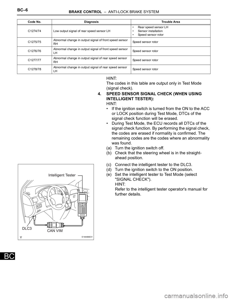
(c) Connect the intelligent tester to the DLC3.
(d) Turn the ignition switch to the ON position.
(e) Set the intelligent tester to Test Mode (select
"SIGNAL CHECK").
HINT:
Refer to the intelligent tester operator's manual for
further details.
C1274/74 Low output signal of rear speed sensor LH• Rear speed sensor LH
• Sensor installation
• Speed sensor rotor
C1275/75Abnormal change in output signal of front speed sensor
RHSpeed sensor rotor
C1276/76Abnormal change in output signal of front speed sensor
LHSpeed sensor rotor
C1277/77Abnormal change in output signal of rear speed sensor
RHSpeed sensor rotor
C1278/78Abnormal change in output signal of rear speed sensor
LHSpeed sensor rotor Code No. Diagnosis Trouble Area
E144486E01
Page 183 of 3000

BRAKE CONTROL – ANTI-LOCK BRAKE SYSTEMBC–7
BC
(f) Check that the ABS warning light is blinking in the
Test Mode.
HINT:
If the ABS warning light does not blink, inspect the
TS and CG terminal circuit and the ABS warning
light circuit.
(g) Start the engine.
(h) Using the intelligent tester, perform the speed
sensor signal check in Test Mode.
(i) Drive the vehicle straight forward.
(j) Accelerate the vehicle to a speed of 28 mph (45 km/
h) or higher for several seconds and check that the
ABS warning light goes off.
HINT:
The signal check may not be completed if the
vehicle has its wheels spun.
(k) Stop the vehicle.
NOTICE:
• The speed sensor signal check may not be
completed if the steering wheel is turned or
the wheels are spun during the check.
• After the ABS warning light goes off and if
vehicle speed exceeds 50 mph (80 km/h), a
signal check code will be stored again.
Decelerate or stop the vehicle before the
speed reaches 50 mph (80 km/h).
• If the signal check has not been completed,
the ABS warning light blinks while driving
and the ABS system does not operate.
HINT:
When the signal check has been completed, the
ABS warning light goes off while driving and blinks
in the Test Mode pattern while stationary.
5. READ DTC
(a) Read the DTC(s) by following the tester screen.
HINT:
• Refer to the intelligent tester operator's manual
for further details.
• See the list of DTC.
6. DTC OF TEST MODE (SIGNAL CHECK) FUNCTION
BR03904E13
Trouble Area See procedure
TS and CG terminal circuitBC-64
ABS warning light circuitBC-47 or BC-50
Code No. Diagnosis Trouble Area
C1271/71 Low output signal of front speed sensor RH• Front speed sensor RH
• Sensor installation
• Speed sensor rotor
C1272/72 Low output signal of front speed sensor LH• Front speed sensor LH
• Sensor installation
• Speed sensor rotor
C1273/73 Low output signal of rear speed sensor RH• Rear speed sensor RH
• Sensor installation
• Speed sensor rotor
Page 184 of 3000

BC–8BRAKE CONTROL – ANTI-LOCK BRAKE SYSTEM
BC
HINT:
The codes in this table are output only in Test Mode
(signal check).
C1274/74 Low output signal of rear speed sensor LH• Rear speed sensor LH
• Sensor installation
• Speed sensor rotor
C1275/75Abnormal change in output signal of front speed sensor
RHSpeed sensor rotor
C1276/76Abnormal change in output signal of front speed sensor
LHSpeed sensor rotor
C1277/77Abnormal change in output signal of rear speed sensor
RHSpeed sensor rotor
C1278/78Abnormal change in output signal of rear speed sensor
LHSpeed sensor rotor Code No. Diagnosis Trouble Area
Page 185 of 3000
BRAKE – BRAKE PEDALBR–11
BR
REMOVAL
1. SEPARATE BATTERY NEGATIVE TERMINAL
2. REMOVE FRONT DOOR SCUFF PLATE LH
3. REMOVE COWL SIDE TRIM BOARD LH
4. REMOVE INSTRUMENT PANEL FINISH PANEL SUB-
ASSEMBLY LOWER LH
(a) Remove the 2 bolts and instrument panel finish
panel sub-assembly lower LH.
5. REMOVE INSTRUMENT PANEL SAFETY PAD
INSERT SUB-ASSEMBLY NO. 1
(a) Remove the 4 bolts and instrument panel safety pad
insert sub-assembly No. 1.
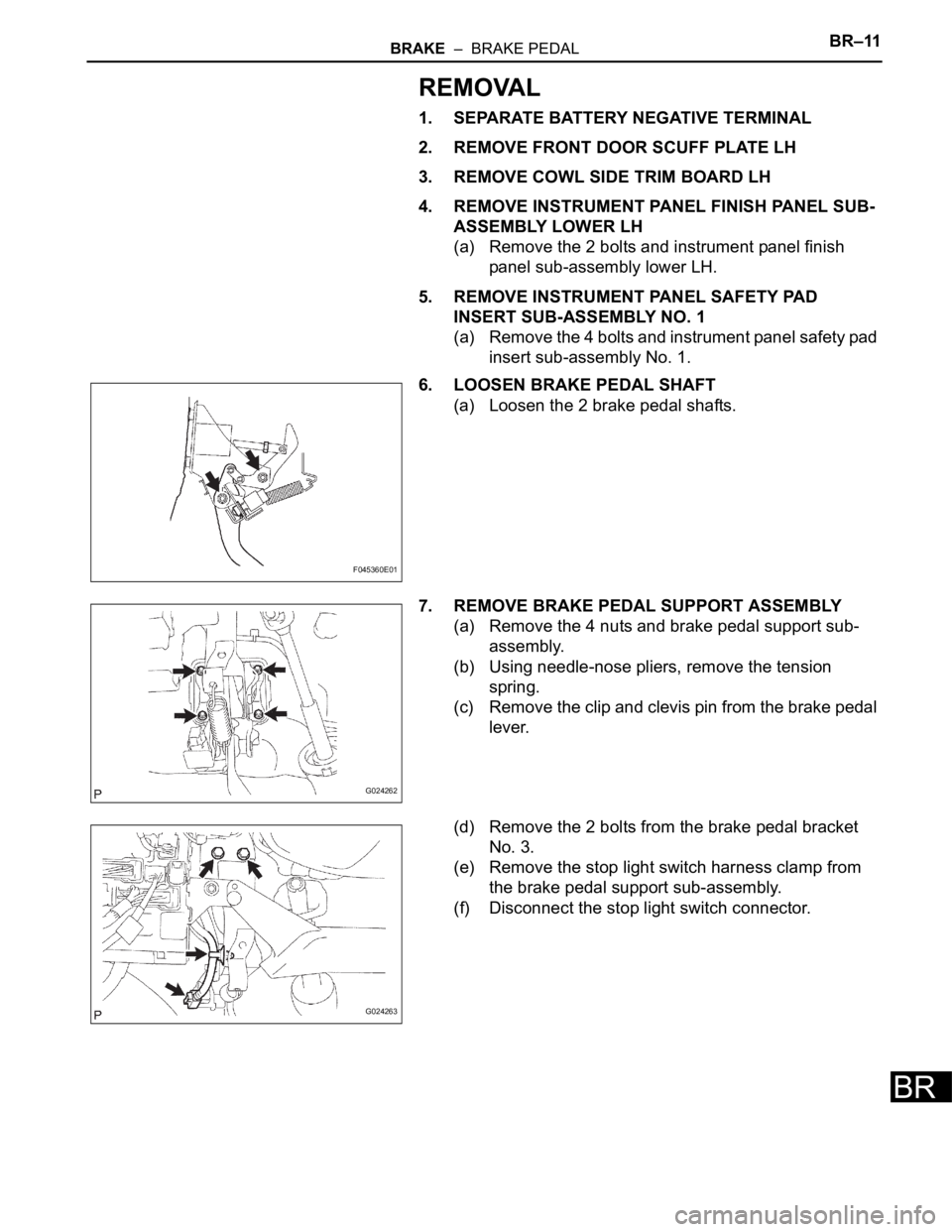
6. LOOSEN BRAKE PEDAL SHAFT
(a) Loosen the 2 brake pedal shafts.
7. REMOVE BRAKE PEDAL SUPPORT ASSEMBLY
(a) Remove the 4 nuts and brake pedal support sub-
assembly.
(b) Using needle-nose pliers, remove the tension
spring.
(c) Remove the clip and clevis pin from the brake pedal
lever.
(d) Remove the 2 bolts from the brake pedal bracket
No. 3.
(e) Remove the stop light switch harness clamp from
the brake pedal support sub-assembly.
(f) Disconnect the stop light switch connector.
F045360E01
G024262
G024263
Page 186 of 3000
BR–12BRAKE – BRAKE PEDAL
BR
DISASSEMBLY
1. REMOVE STOP LIGHT SWITCH ASSEMBLY
(a) Turn the stop light switch assembly
counterclockwise and remove the stop light switch
assembly.
(b) Remove the stop light switch mounting adjuster
from the brake pedal support sub-assembly.
2. REMOVE STOP LIGHT SWITCH CUSHION
(a) Remove the stop light switch cushion from the brake
pedal sub-assembly.
3. REMOVE BRAKE PEDAL
(a) Remove the 2 brake pedal shafts, 2 nuts and brake
pedal from the brake pedal support sub-assembly.
4. REMOVE BRAKE PEDAL BUSH
(a) Remove the 4 brake pedal bushes from the brake
pedal.
5. REMOVE BRAKE PEDAL SHAFT COLLAR
(a) Remove the 2 brake pedal shaft collars from the
brake pedal.
6. REMOVE PUSH ROD PIN
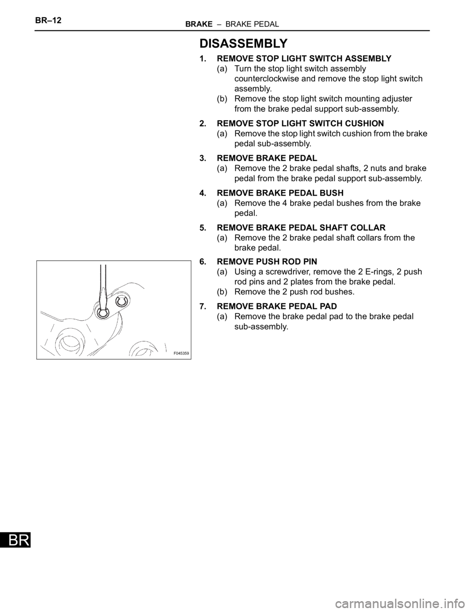
(a) Using a screwdriver, remove the 2 E-rings, 2 push
rod pins and 2 plates from the brake pedal.
(b) Remove the 2 push rod bushes.
7. REMOVE BRAKE PEDAL PAD
(a) Remove the brake pedal pad to the brake pedal
sub-assembly.
F045359
Page 187 of 3000
PARKING BRAKE – PARKING BRAKE PEDALPB–5
PB
REMOVAL
1. DISCONNECT BATTERY NEGATIVE TERMINAL
2. REMOVE FRONT DOOR SCUFF PLATE LH
3. REMOVE COWL SIDE TRIM BOARD LH
4. REMOVE INSTRUMENT PANEL FINISH PANEL SUB-
ASSEMBLY LOWER LH (See page IP-6)
5. REMOVE REAR DOOR SCUFF PLATE RH
6. REMOVE REAR DOOR SCUFF PLATE LH
7. REMOVE FRONT SEAT ASSEMBLY LH
HINT:
• Manual Seat Type (See page SE-48)
• Power Seat Type (See page SE-58)
• Fold Flat Type (See page SE-40)
8. REMOVE REAR SEAT NO.1 ASSEMBLY
HINT:
• Captain Seat Type (See page SE-68)
• Center Seat Type (See page SE-77)
9. REMOVE REAR FLOOR SEAT LOCK COVER
10. REMOVE REAR FLOOR SEAT LOCK COVER
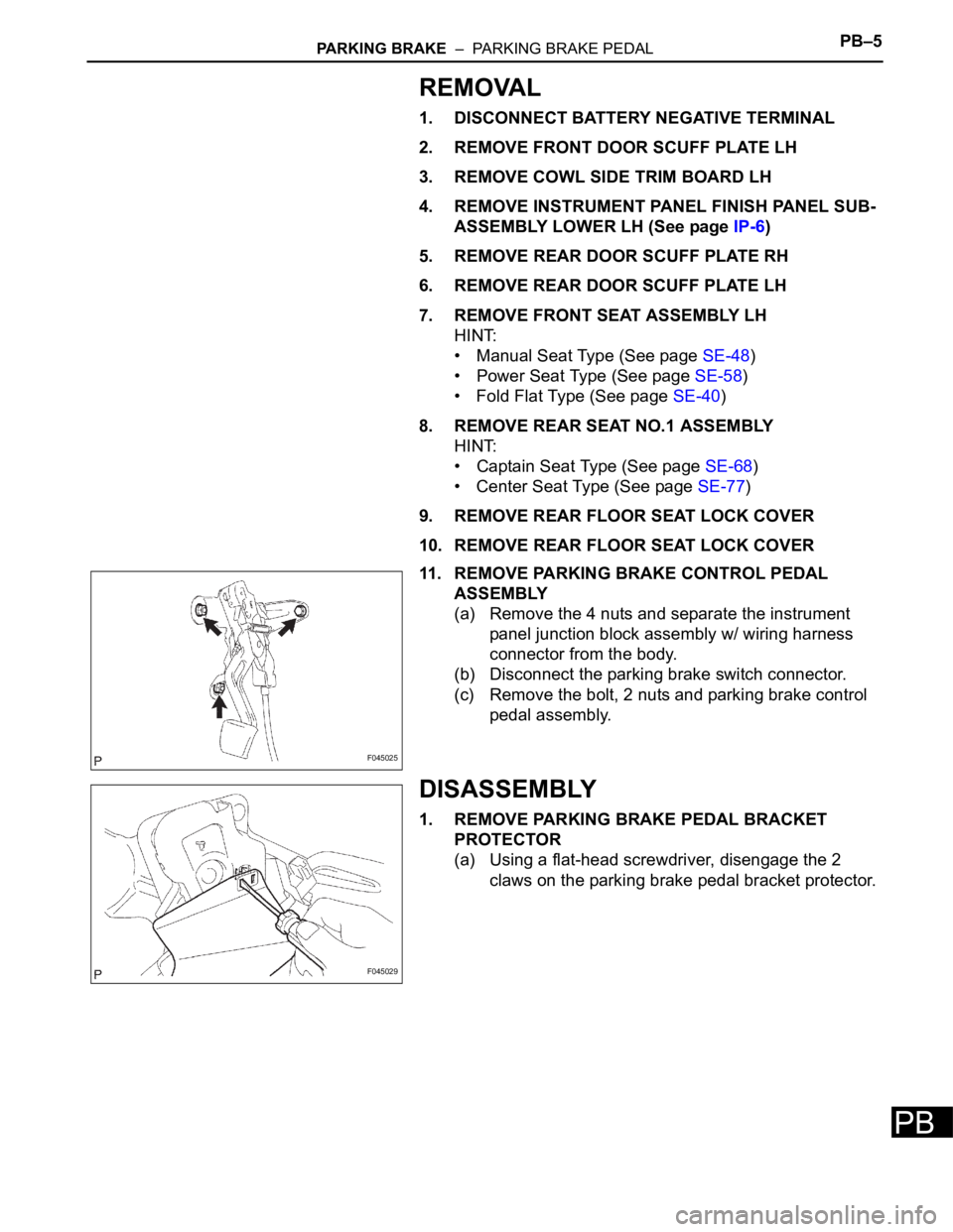
11. REMOVE PARKING BRAKE CONTROL PEDAL
ASSEMBLY
(a) Remove the 4 nuts and separate the instrument
panel junction block assembly w/ wiring harness
connector from the body.
(b) Disconnect the parking brake switch connector.
(c) Remove the bolt, 2 nuts and parking brake control
pedal assembly.
DISASSEMBLY
1. REMOVE PARKING BRAKE PEDAL BRACKET
PROTECTOR
(a) Using a flat-head screwdriver, disengage the 2
claws on the parking brake pedal bracket protector.
F045025
F045029
Page 188 of 3000
PB–6PARKING BRAKE – PARKING BRAKE PEDAL
PB
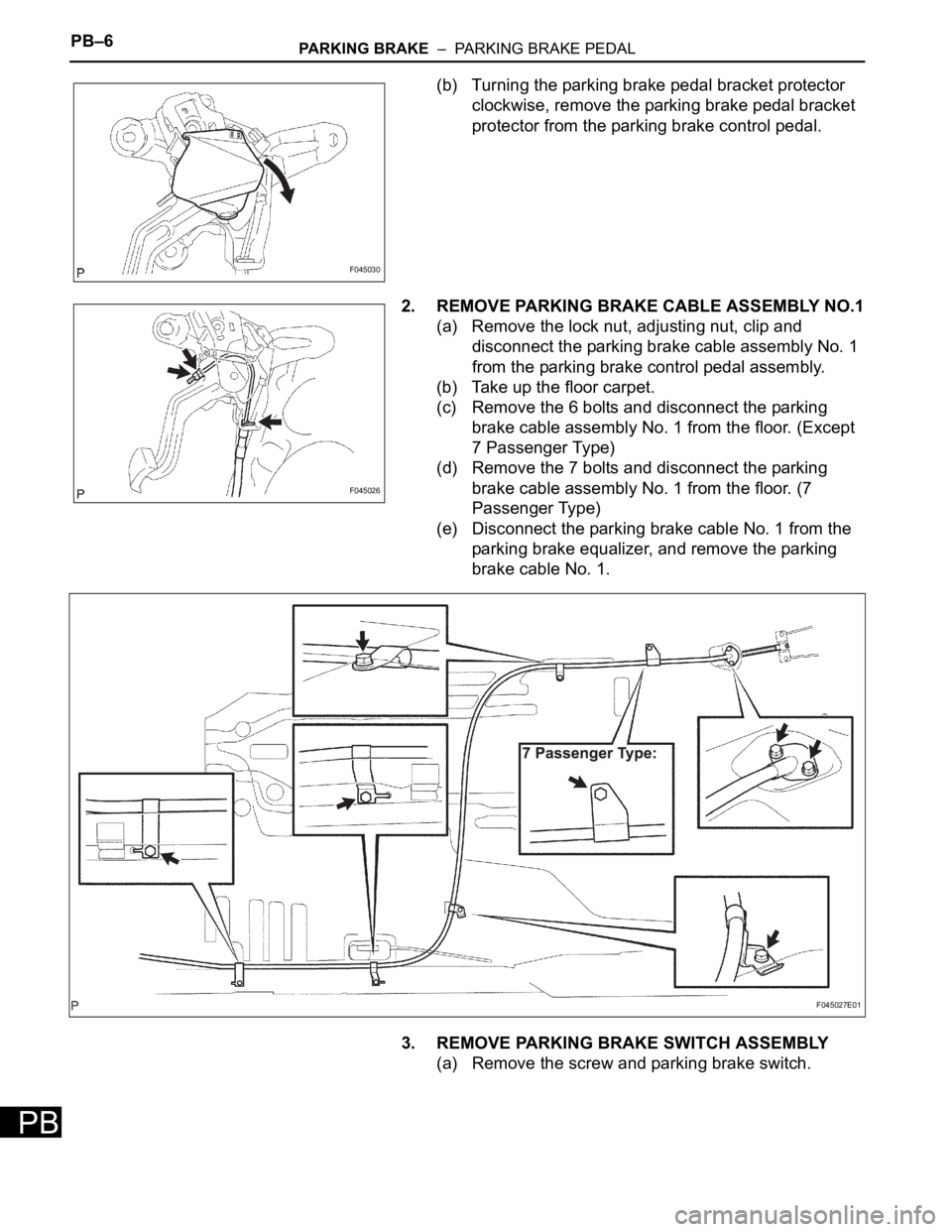
(b) Turning the parking brake pedal bracket protector
clockwise, remove the parking brake pedal bracket
protector from the parking brake control pedal.
2. REMOVE PARKING BRAKE CABLE ASSEMBLY NO.1
(a) Remove the lock nut, adjusting nut, clip and
disconnect the parking brake cable assembly No. 1
from the parking brake control pedal assembly.
(b) Take up the floor carpet.
(c) Remove the 6 bolts and disconnect the parking
brake cable assembly No. 1 from the floor. (Except
7 Passenger Type)
(d) Remove the 7 bolts and disconnect the parking
brake cable assembly No. 1 from the floor. (7
Passenger Type)
(e) Disconnect the parking brake cable No. 1 from the
parking brake equalizer, and remove the parking
brake cable No. 1.
3. REMOVE PARKING BRAKE SWITCH ASSEMBLY
(a) Remove the screw and parking brake switch.
F045030
F045026
F045027E01
Page 189 of 3000
STEERING COLUMN – STEERING SYSTEMSR–3
SR
REPAIR
1. STEERING OFF CENTER REPAIR PROCEDURE
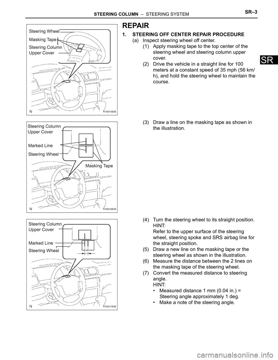
(a) Inspect steering wheel off center.
(1) Apply masking tape to the top center of the
steering wheel and steering column upper
cover.
(2) Drive the vehicle in a straight line for 100
meters at a constant speed of 35 mph (56 km/
h), and hold the steering wheel to maintain the
course.
(3) Draw a line on the masking tape as shown in
the illustration.
(4) Turn the steering wheel to its straight position.
HINT:
Refer to the upper surface of the steering
wheel, steering spoke and SRS airbag line for
the straight position.
(5) Draw a new line on the masking tape or the
steering wheel as shown in the illustration.
(6) Measure the distance between the 2 lines on
the masking tape of the steering wheel.
(7) Convert the measured distance to steering
angle.
HINT:
• Measured distance 1 mm (0.04 in.) =
Steering angle approximately 1 deg.
• Make a note of the steering angle.
F016015E06
F016016E09
F016017E06
Page 190 of 3000
SR–4STEERING COLUMN – STEERING SYSTEM
SR
(b) Adjust the steering angle.
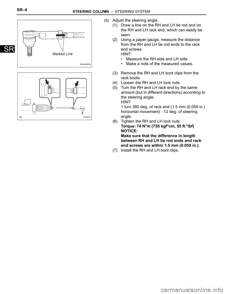
(1) Draw a line on the RH and LH tie rod and on
the RH and LH rack end, which can easily be
seen.
(2) Using a paper gauge, measure the distance
from the RH and LH tie rod ends to the rack
end screws.
HINT:
• Measure the RH side and LH side.
• Make a note of the measured values.
(3) Remove the RH and LH boot clips from the
rack boots.
(4) Loosen the RH and LH lock nuts.
(5) Turn the RH and LH rack end by the same
amount (but in different directions) according to
the steering angle.
HINT:
1 turn 360 deg. of rack end (1.5 mm (0.059 in.)
horizontal movement) - 12 deg. of steering
angle.
(6) Tighten the RH and LH lock nuts.
Torque: 74 N*m (755 kgf*cm, 55 ft.*lbf)
NOTICE:
Make sure that the difference in length
between RH and LH tie rod ends and rack
end screws are within 1.5 mm (0.059 in.).
(7) Install the RH and LH boot clips.
R000429E08
F016018