TOYOTA SIENNA 2007 Service Repair Manual
Manufacturer: TOYOTA, Model Year: 2007, Model line: SIENNA, Model: TOYOTA SIENNA 2007Pages: 3000, PDF Size: 52.26 MB
Page 161 of 3000
DIFFERENTIAL – REAR DIFFERENTIAL CARRIER OIL SEALDF–7
DF
INSTALLATION
1. INSTALL REAR DIFFERENTIAL DRIVE PINION
BEARING SPACER
(a) Install a new bearing spacer.
2. INSTALL REAR DRIVE PINION FRONT TAPERED
ROLLER BEARING
(a) Install the tapered roller bearing.
3. INSTALL REAR DIFFERENTIAL DRIVE PINION OIL
SLINGER
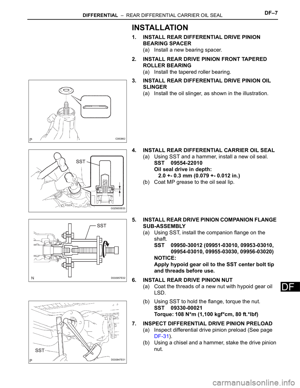
(a) Install the oil slinger, as shown in the illustration.
4. INSTALL REAR DIFFERENTIAL CARRIER OIL SEAL
(a) Using SST and a hammer, install a new oil seal.
SST 09554-22010
Oil seal drive in depth:
2.0 +- 0.3 mm (0.079 +- 0.012 in.)
(b) Coat MP grease to the oil seal lip.
5. INSTALL REAR DRIVE PINION COMPANION FLANGE
SUB-ASSEMBLY
(a) Using SST, install the companion flange on the
shaft.
SST 09950-30012 (09951-03010, 09953-03010,
09954-03010, 09955-03030, 09956-03020)
NOTICE:
Apply hypoid gear oil to the SST center bolt tip
and threads before use.
6. INSTALL REAR DRIVE PINION NUT
(a) Coat the threads of a new nut with hypoid gear oil
LSD.
(b) Using SST to hold the flange, torque the nut.
SST 09330-00021
Torque: 108 N*m (1,100 kgf*cm, 80 ft.*lbf)
7. INSPECT DIFFERENTIAL DRIVE PINION PRELOAD
(a) Inspect differential drive pinion preload (See page
DF-31).
(b) Using a chisel and a hammer, stake the drive pinion
nut.
C083862
G025655E03
D030957E02
D030847E01
Page 162 of 3000
DF–8DIFFERENTIAL – REAR DIFFERENTIAL CARRIER OIL SEAL
DF
8. INSTALL REAR DIFFERENTIAL DRAIN PLUG
(a) Using a hexagon wrench (10 mm), install the filler
plug with a new gasket.
Torque: 49 N*m (500 kgf*cm, 36 ft.*lbf)
9. ADD DIFFERENTIAL OIL
(a) Fill the rear differential carrier assembly with hypoid
gear oil.
10. INSPECT DIFFERENTIAL OIL
HINT:
(See page DF-3)
11. INSTALL REAR DIFFERENTIAL FILLER PLUG
(a) Using a hexagon wrench (10 mm), install the filler
plug with a new gasket.
Torque: 49 N*m (500 kgf*cm, 36 ft.*lbf)
12. INSTALL PROPELLER WITH CENTER BEARING
SHAFT ASSEMBLY
(a) Install propeller with center bearing shaft assembly
(See page PR-9).
(b) Fully tighten propeller with center bearing shaft
assembly (See page PR-10).
13. INSTALL EXHAUST PIPE ASSEMBLY
HINT:
(See page EX-10)
14. INSPECT FOR EXHAUST GAS LEAK
HINT:
(See page EX-12)
Page 163 of 3000
AH–6AXLE – FRONT AXLE HUB
AH
REMOVAL
HINT:
Replace the RH side using the same procedures as for the
LH side.
1. REMOVE FRONT WHEEL
2. REMOVE FRONT AXLE HUB LH NUT (See page DS-
5)
3. SEPARATE SPEED SENSOR FRONT LH (See page
DS-5)
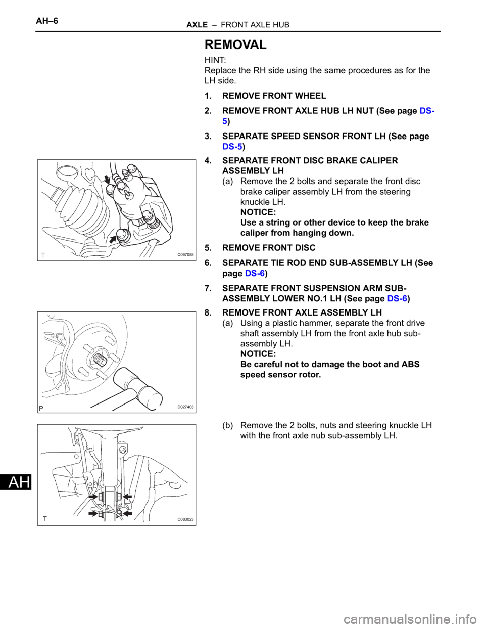
4. SEPARATE FRONT DISC BRAKE CALIPER
ASSEMBLY LH
(a) Remove the 2 bolts and separate the front disc
brake caliper assembly LH from the steering
knuckle LH.
NOTICE:
Use a string or other device to keep the brake
caliper from hanging down.
5. REMOVE FRONT DISC
6. SEPARATE TIE ROD END SUB-ASSEMBLY LH (See
page DS-6)
7. SEPARATE FRONT SUSPENSION ARM SUB-
ASSEMBLY LOWER NO.1 LH (See page DS-6)
8. REMOVE FRONT AXLE ASSEMBLY LH
(a) Using a plastic hammer, separate the front drive
shaft assembly LH from the front axle hub sub-
assembly LH.
NOTICE:
Be careful not to damage the boot and ABS
speed sensor rotor.
(b) Remove the 2 bolts, nuts and steering knuckle LH
with the front axle nub sub-assembly LH.
C067088
D027403
C083023
Page 164 of 3000
AXLE – FRONT AXLE HUBAH–7
AH
DISASSEMBLY
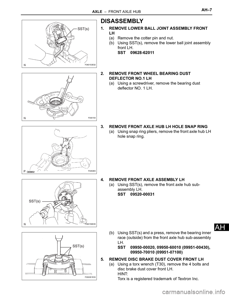
1. REMOVE LOWER BALL JOINT ASSEMBLY FRONT
LH
(a) Remove the cotter pin and nut.
(b) Using SST(s), remove the lower ball joint assembly
front LH.
SST 09628-62011
2. REMOVE FRONT WHEEL BEARING DUST
DEFLECTOR NO.1 LH
(a) Using a screwdriver, remove the bearing dust
deflector NO. 1 LH.
3. REMOVE FRONT AXLE HUB LH HOLE SNAP RING
(a) Using snap ring pliers, remove the front axle hub LH
hole snap ring.
4. REMOVE FRONT AXLE ASSEMBLY LH
(a) Using SST(s), remove the front axle hub sub-
assembly LH.
SST 09520-00031
(b) Using SST(s) and a press, remove the bearing inner
race (outside) from the front axle hub sub-assembly
LH.
SST 09950-00020, 09950-60010 (09951-00430),
09950-70010 (09951-07100)
5. REMOVE DISC BRAKE DUST COVER FRONT LH
(a) Using a torx wrench (T30), remove the 4 bolts and
disc brake dust cover front LH.
HINT:
Torx is a registered trademark of Textron Inc.
F040153E02
F040154
F045465
F040156E05
F002261E03
Page 165 of 3000
AH–8AXLE – FRONT AXLE HUB
AH
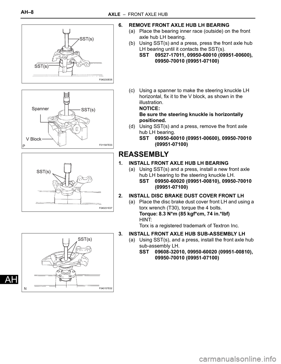
6. REMOVE FRONT AXLE HUB LH BEARING
(a) Place the bearing inner race (outside) on the front
axle hub LH bearing.
(b) Using SST(s) and a press, press the front axle hub
LH bearing until it contacts the SST(s).
SST 09527-17011, 09950-60010 (09951-00600),
09950-70010 (09951-07100)
(c) Using a spanner to make the steering knuckle LH
horizontal, fix it to the V block, as shown in the
illustration.
NOTICE:
Be sure the steering knuckle is horizontally
positioned.
(d) Using SST(s) and a press, remove the front axle
hub LH bearing.
SST 09950-60010 (09951-00600), 09950-70010
(09951-07100)
REASSEMBLY
1. INSTALL FRONT AXLE HUB LH BEARING
(a) Using SST(s) and a press, install a new front axle
hub LH bearing to the steering knuckle LH.
SST 09950-60020 (09951-00810), 09950-70010
(09951-07100)
2. INSTALL DISC BRAKE DUST COVER FRONT LH
(a) Place the disc brake dust cover front LH and using a
torx wrench (T30), torque the 4 bolts.
Torque: 8.3 N*m (85 kgf*cm, 74 in.*lbf)
HINT:
Torx is a registered trademark of Textron Inc.
3. INSTALL FRONT AXLE HUB SUB-ASSEMBLY LH
(a) Using SST(s), and a press, install the front axle hub
sub-assembly LH.
SST 09608-32010, 09950-60020 (09951-00810),
09950-70010 (09951-07100)
F040230E05
F011547E03
F040231E07
F040157E02
Page 166 of 3000
AXLE – FRONT AXLE HUBAH–9
AH
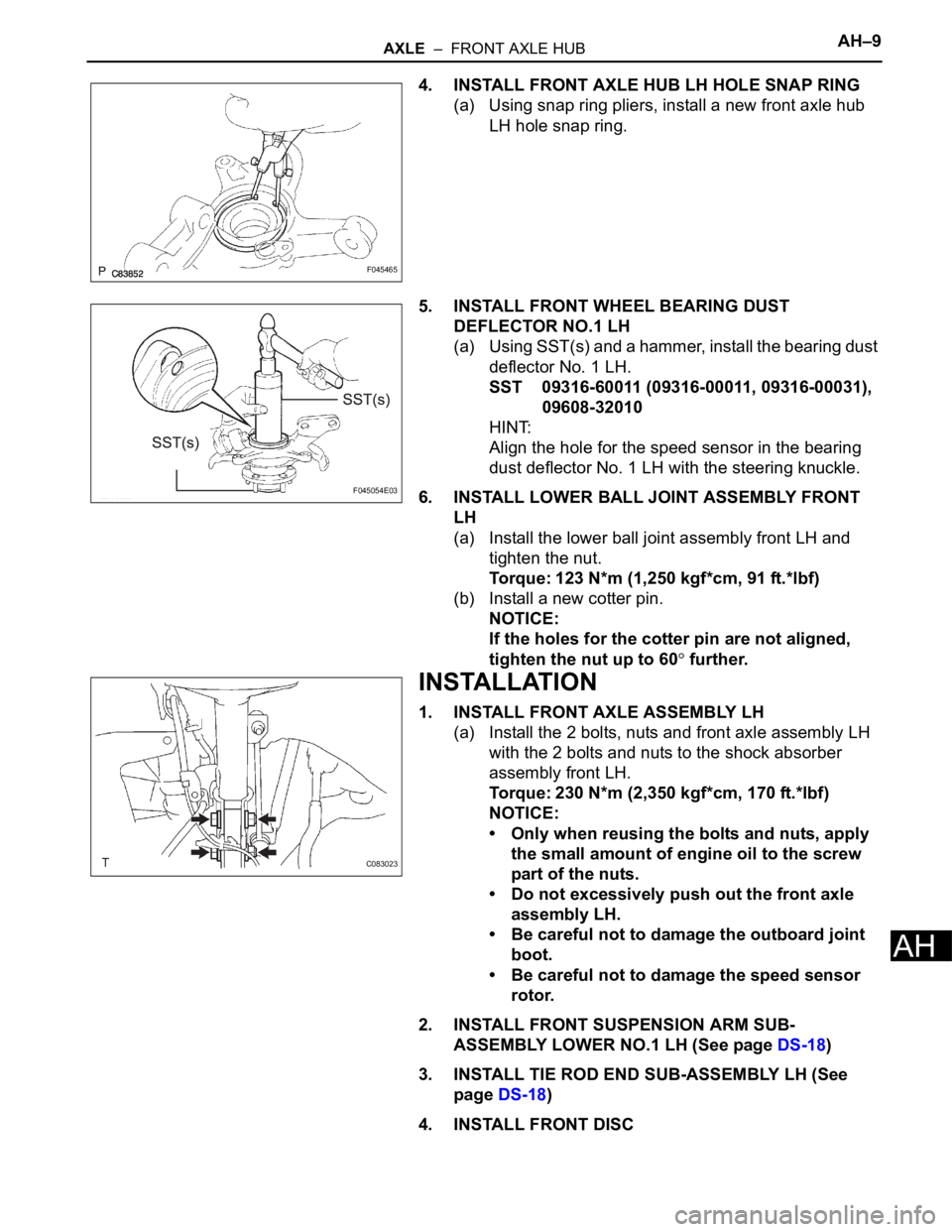
4. INSTALL FRONT AXLE HUB LH HOLE SNAP RING
(a) Using snap ring pliers, install a new front axle hub
LH hole snap ring.
5. INSTALL FRONT WHEEL BEARING DUST
DEFLECTOR NO.1 LH
(a) Using SST(s) and a hammer, install the bearing dust
deflector No. 1 LH.
SST 09316-60011 (09316-00011, 09316-00031),
09608-32010
HINT:
Align the hole for the speed sensor in the bearing
dust deflector No. 1 LH with the steering knuckle.
6. INSTALL LOWER BALL JOINT ASSEMBLY FRONT
LH
(a) Install the lower ball joint assembly front LH and
tighten the nut.
Torque: 123 N*m (1,250 kgf*cm, 91 ft.*lbf)
(b) Install a new cotter pin.
NOTICE:
If the holes for the cotter pin are not aligned,
tighten the nut up to 60
further.
INSTALLATION
1. INSTALL FRONT AXLE ASSEMBLY LH
(a) Install the 2 bolts, nuts and front axle assembly LH
with the 2 bolts and nuts to the shock absorber
assembly front LH.
Torque: 230 N*m (2,350 kgf*cm, 170 ft.*lbf)
NOTICE:
• Only when reusing the bolts and nuts, apply
the small amount of engine oil to the screw
part of the nuts.
• Do not excessively push out the front axle
assembly LH.
• Be careful not to damage the outboard joint
boot.
• Be careful not to damage the speed sensor
rotor.
2. INSTALL FRONT SUSPENSION ARM SUB-
ASSEMBLY LOWER NO.1 LH (See page DS-18)
3. INSTALL TIE ROD END SUB-ASSEMBLY LH (See
page DS-18)
4. INSTALL FRONT DISC
F045465
F045054E03
C083023
Page 167 of 3000
AH–10AXLE – FRONT AXLE HUB
AH
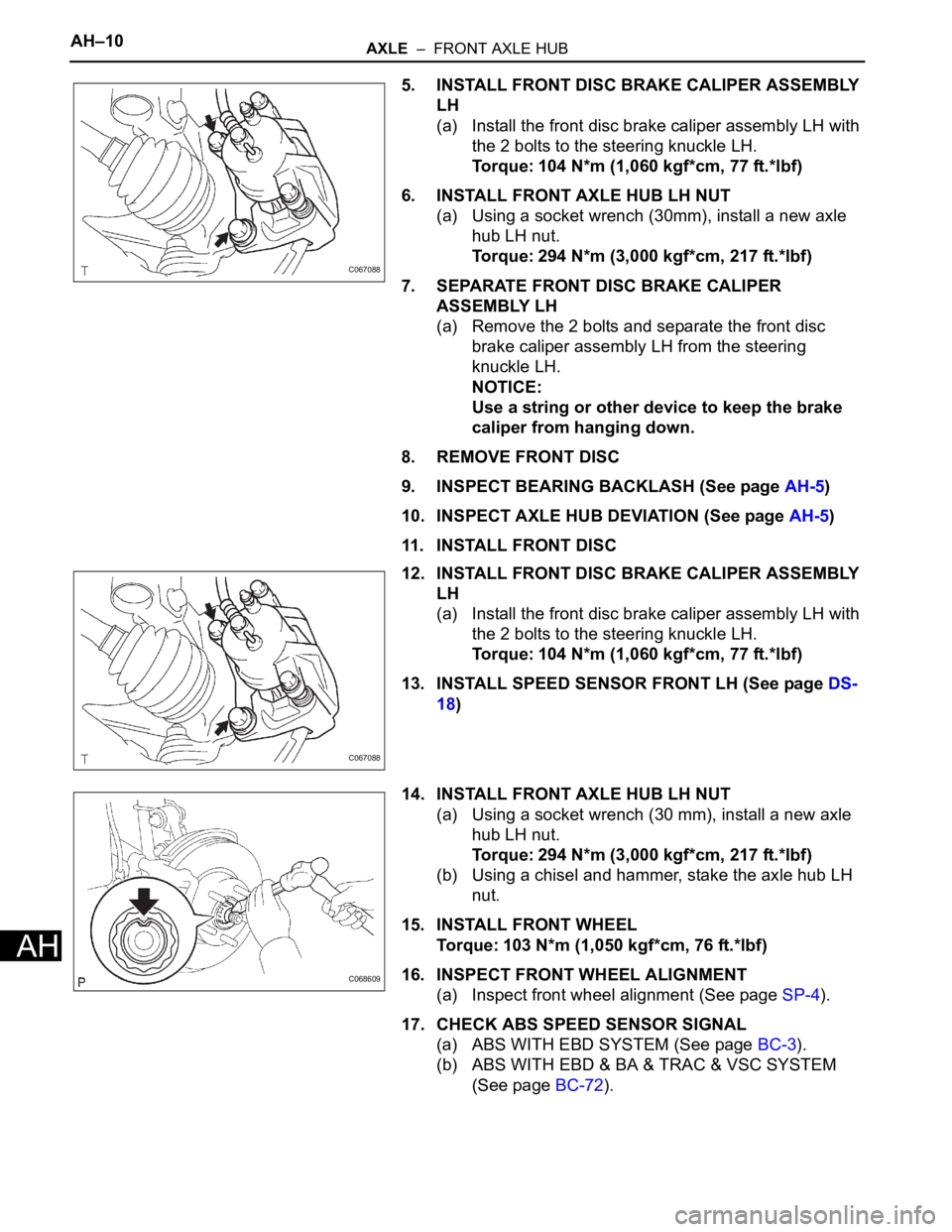
5. INSTALL FRONT DISC BRAKE CALIPER ASSEMBLY
LH
(a) Install the front disc brake caliper assembly LH with
the 2 bolts to the steering knuckle LH.
Torque: 104 N*m (1,060 kgf*cm, 77 ft.*lbf)
6. INSTALL FRONT AXLE HUB LH NUT
(a) Using a socket wrench (30mm), install a new axle
hub LH nut.
Torque: 294 N*m (3,000 kgf*cm, 217 ft.*lbf)
7. SEPARATE FRONT DISC BRAKE CALIPER
ASSEMBLY LH
(a) Remove the 2 bolts and separate the front disc
brake caliper assembly LH from the steering
knuckle LH.
NOTICE:
Use a string or other device to keep the brake
caliper from hanging down.
8. REMOVE FRONT DISC
9. INSPECT BEARING BACKLASH (See page AH-5)
10. INSPECT AXLE HUB DEVIATION (See page AH-5)
11. INSTALL FRONT DISC
12. INSTALL FRONT DISC BRAKE CALIPER ASSEMBLY
LH
(a) Install the front disc brake caliper assembly LH with
the 2 bolts to the steering knuckle LH.
Torque: 104 N*m (1,060 kgf*cm, 77 ft.*lbf)
13. INSTALL SPEED SENSOR FRONT LH (See page DS-
18)
14. INSTALL FRONT AXLE HUB LH NUT
(a) Using a socket wrench (30 mm), install a new axle
hub LH nut.
Torque: 294 N*m (3,000 kgf*cm, 217 ft.*lbf)
(b) Using a chisel and hammer, stake the axle hub LH
nut.
15. INSTALL FRONT WHEEL
Torque: 103 N*m (1,050 kgf*cm, 76 ft.*lbf)
16. INSPECT FRONT WHEEL ALIGNMENT
(a) Inspect front wheel alignment (See page SP-4).
17. CHECK ABS SPEED SENSOR SIGNAL
(a) ABS WITH EBD SYSTEM (See page BC-3).
(b) ABS WITH EBD & BA & TRAC & VSC SYSTEM
(See page BC-72).
C067088
C067088
C068609
Page 168 of 3000
SUSPENSION – SUSPENSION SYSTEMSP–3
SP
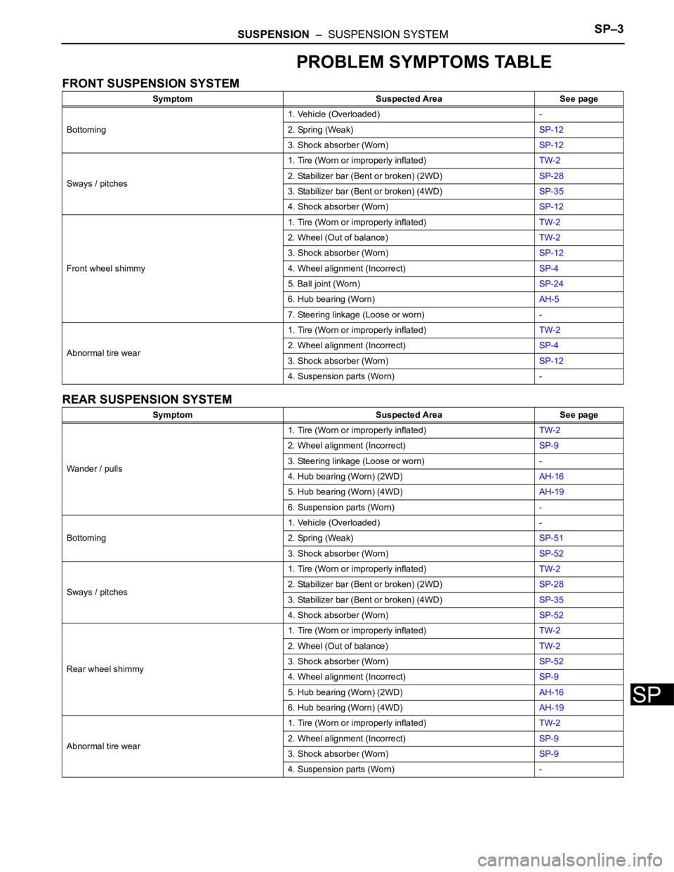
PROBLEM SYMPTOMS TABLE
FRONT SUSPENSION SYSTEM
REAR SUSPENSION SYSTEM
Symptom Suspected Area See page
Bottoming1. Vehicle (Overloaded) -
2. Spring (Weak)SP-12
3. Shock absorber (Worn)SP-12
Sways / pitches1. Tire (Worn or improperly inflated)TW-2
2. Stabilizer bar (Bent or broken) (2WD)SP-28
3. Stabilizer bar (Bent or broken) (4WD)SP-35
4. Shock absorber (Worn)SP-12
Front wheel shimmy1. Tire (Worn or improperly inflated)TW-2
2. Wheel (Out of balance)TW-2
3. Shock absorber (Worn)SP-12
4. Wheel alignment (Incorrect)SP-4
5. Ball joint (Worn)SP-24
6. Hub bearing (Worn)AH-5
7. Steering linkage (Loose or worn) -
Abnormal tire wear1. Tire (Worn or improperly inflated)TW-2
2. Wheel alignment (Incorrect)SP-4
3. Shock absorber (Worn)SP-12
4. Suspension parts (Worn) -
Symptom Suspected Area See page
Wander / pulls1. Tire (Worn or improperly inflated)TW-2
2. Wheel alignment (Incorrect)SP-9
3. Steering linkage (Loose or worn) -
4. Hub bearing (Worn) (2WD)AH-16
5. Hub bearing (Worn) (4WD)AH-19
6. Suspension parts (Worn) -
Bottoming1. Vehicle (Overloaded) -
2. Spring (Weak)SP-51
3. Shock absorber (Worn)SP-52
Sways / pitches1. Tire (Worn or improperly inflated)TW-2
2. Stabilizer bar (Bent or broken) (2WD)SP-28
3. Stabilizer bar (Bent or broken) (4WD)SP-35
4. Shock absorber (Worn)SP-52
Rear wheel shimmy1. Tire (Worn or improperly inflated)TW-2
2. Wheel (Out of balance)TW-2
3. Shock absorber (Worn)SP-52
4. Wheel alignment (Incorrect)SP-9
5. Hub bearing (Worn) (2WD)AH-16
6. Hub bearing (Worn) (4WD)AH-19
Abnormal tire wear1. Tire (Worn or improperly inflated)TW-2
2. Wheel alignment (Incorrect)SP-9
3. Shock absorber (Worn)SP-9
4. Suspension parts (Worn) -
Page 169 of 3000
SUSPENSION – REAR SHOCK ABSORBERSP–51
SP
REMOVAL
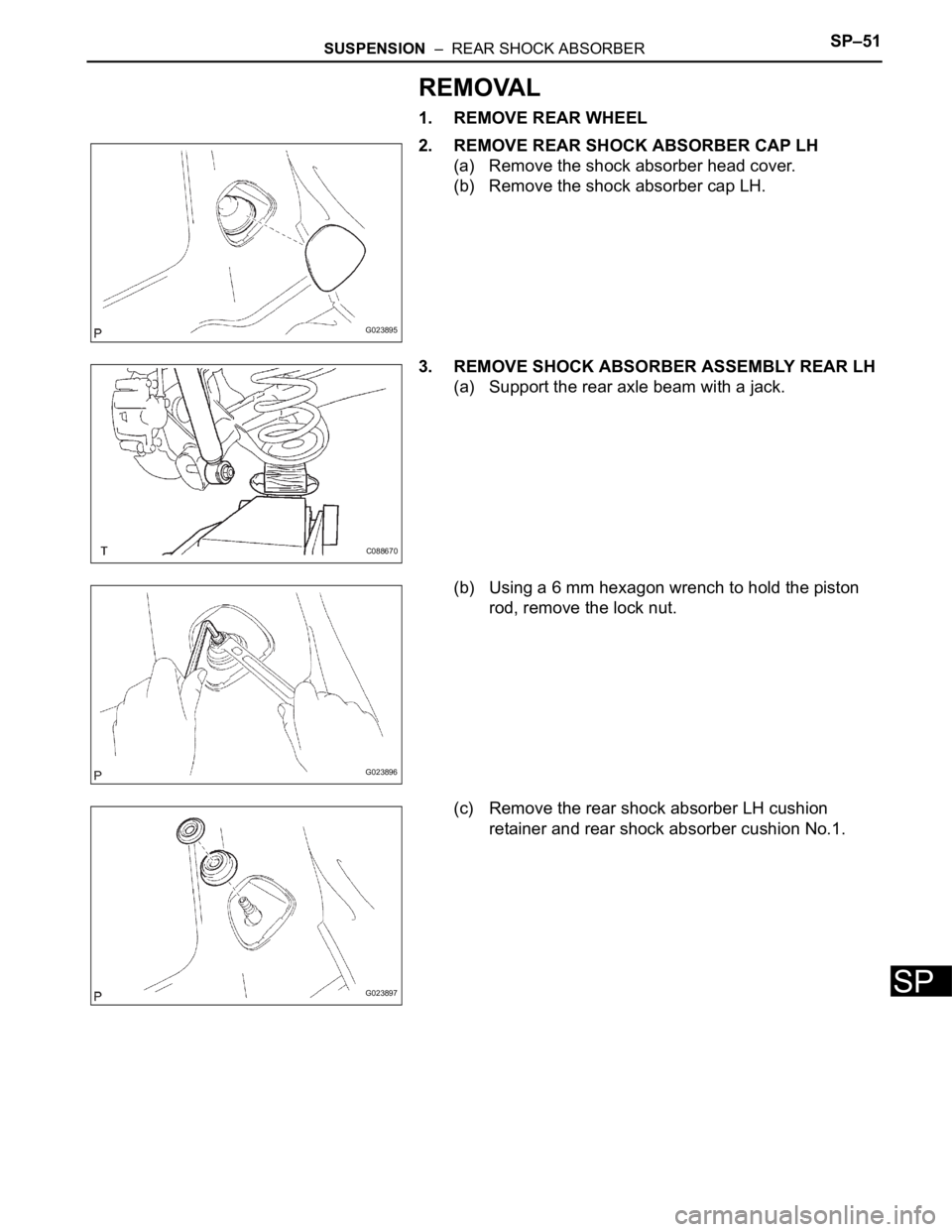
1. REMOVE REAR WHEEL
2. REMOVE REAR SHOCK ABSORBER CAP LH
(a) Remove the shock absorber head cover.
(b) Remove the shock absorber cap LH.
3. REMOVE SHOCK ABSORBER ASSEMBLY REAR LH
(a) Support the rear axle beam with a jack.
(b) Using a 6 mm hexagon wrench to hold the piston
rod, remove the lock nut.
(c) Remove the rear shock absorber LH cushion
retainer and rear shock absorber cushion No.1.
G023895
C088670
G023896
G023897
Page 170 of 3000
SP–52SUSPENSION – REAR SHOCK ABSORBER
SP
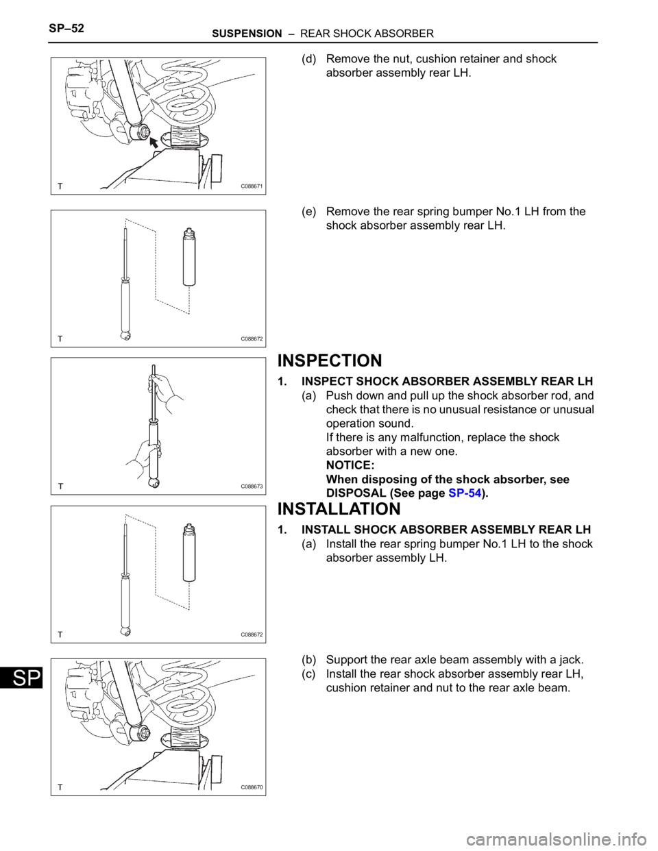
(d) Remove the nut, cushion retainer and shock
absorber assembly rear LH.
(e) Remove the rear spring bumper No.1 LH from the
shock absorber assembly rear LH.
INSPECTION
1. INSPECT SHOCK ABSORBER ASSEMBLY REAR LH
(a) Push down and pull up the shock absorber rod, and
check that there is no unusual resistance or unusual
operation sound.
If there is any malfunction, replace the shock
absorber with a new one.
NOTICE:
When disposing of the shock absorber, see
DISPOSAL (See page SP-54).
INSTALLATION
1. INSTALL SHOCK ABSORBER ASSEMBLY REAR LH
(a) Install the rear spring bumper No.1 LH to the shock
absorber assembly LH.
(b) Support the rear axle beam assembly with a jack.
(c) Install the rear shock absorber assembly rear LH,
cushion retainer and nut to the rear axle beam.
C088671
C088672
C088673
C088672
C088670