YAMAHA VX110 2005 Owners Manual
Manufacturer: YAMAHA, Model Year: 2005, Model line: VX110, Model: YAMAHA VX110 2005Pages: 347, PDF Size: 14.17 MB
Page 91 of 347
4-14
EFUEL
THROTTLE BODY ASSEMBLY AND INTAKE
MANIFOLD
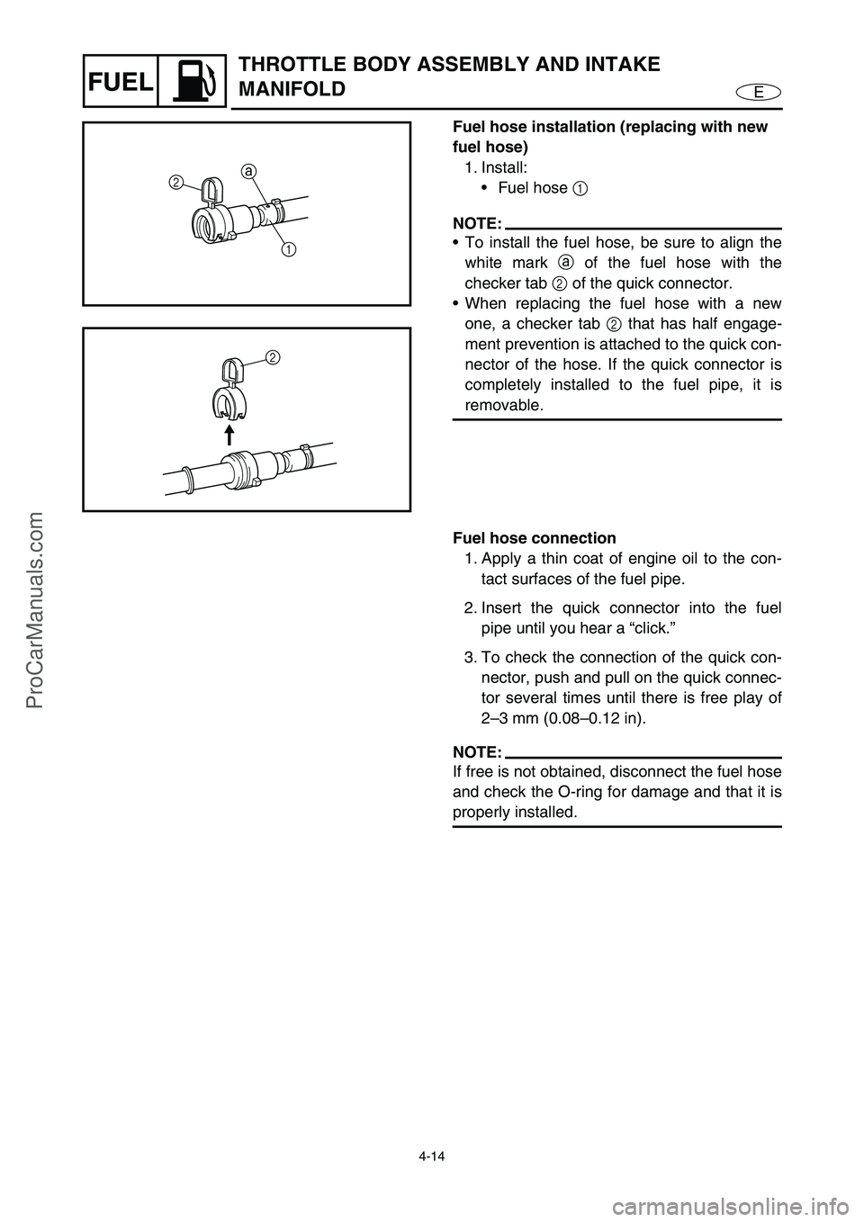
Fuel hose installation (replacing with new
fuel hose)
1. Install:
Fuel hose 1
NOTE:
To install the fuel hose, be sure to align the
white mark a
of the fuel hose with the
checker tab 2
of the quick connector.
When replacing the fuel hose with a new
one, a checker tab 2
that has half engage-
ment prevention is attached to the quick con-
nector of the hose. If the quick connector is
completely installed to the fuel pipe, it is
removable.
2
1a
2
Fuel hose connection
1. Apply a thin coat of engine oil to the con-
tact surfaces of the fuel pipe.
2. Insert the quick connector into the fuel
pipe until you hear a “click.”
3. To check the connection of the quick con-
nector, push and pull on the quick connec-
tor several times until there is free play of
2–3 mm (0.08–0.12 in).
NOTE:
If free is not obtained, disconnect the fuel hose
and check the O-ring for damage and that it is
properly installed.
ProCarManuals.com
Page 92 of 347

4-15
EFUEL
THROTTLE BODY ASSEMBLY AND INTAKE
MANIFOLD
Fuel injectors inspection
NOTE:
Do not remove the throttle body assembly.
1. Check:
Fuel injectors
Dirt/residue →
Clean.
Damage →
Replace.
2. Measure:
Fuel injectors resistance
Out of specification →
Replace.
3. Check the operation of the fuel injector
using the “Stationary Test” of the Yamaha
Diagnostic System.
Digital multimeter:
YU-34899-A
Digital circuit tester:
90890-03174
Fuel injector resistance:
(reference data)
11.5–12.5
Ω at 20 °C (68 °F)
Throttle body assembly inspection
CAUTION:
The throttle body assembly should not be
disassembled.
1. Check:
Throttle body assembly
Cracks/damage →
Replace the throttle
body assembly.
Accelerator position sensor inspection
1. Inspect:
Accelerator position sensor
Damage/cracks →
Replace the acceler-
ator position sensor.
ProCarManuals.com
Page 93 of 347

4-16
EFUEL
THROTTLE BODY ASSEMBLY AND INTAKE
MANIFOLD
Intake assembly installation
1. Install:
Intake screw clamp
Intake manifold joint
Intake assembly
NOTE:
Install the intake screw clamp in the direction
shown in the illustration, making sure to align
the indentation in the clamp with the projec-
tion a
on the intake manifold joint.
Tighten the clamp screw until both ends of
the intake screw clamp contact the spacer 1
around the screw.
a
11
2. Install:
Fuel hose 2 (fuel rail side)
Fuel hose clamps
WARNING
Do not reuse the fuel hose clamps, always
replace them with new ones.
NOTE:
Install the fuel hose with the white mark a
facing up.
Install the fuel hose clamps at the locations
shown in the illustration, and then crimp
them to securely fasten them.
2a
8 mm (0.31 in) 6 mm (0.24 in)
ProCarManuals.com
Page 94 of 347
4-17
EFUEL
THROTTLE BODY ASSEMBLY AND INTAKE
MANIFOLD
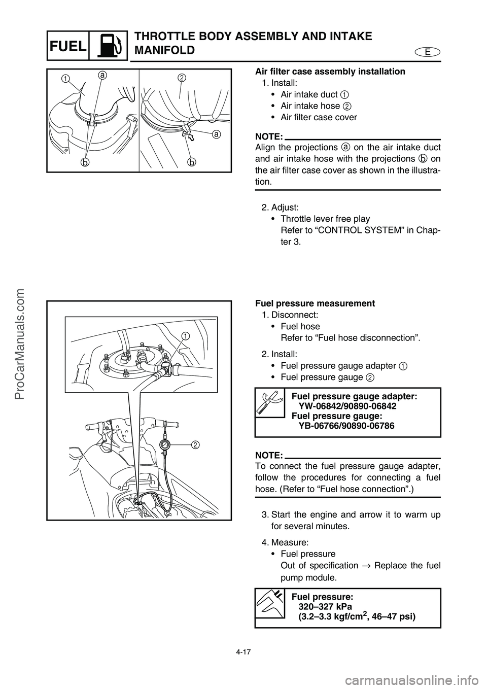
Air filter case assembly installation
1. Install:
Air intake duct 1
Air intake hose 2
Air filter case cover
NOTE:
Align the projections a
on the air intake duct
and air intake hose with the projections b
on
the air filter case cover as shown in the illustra-
tion.
2. Adjust:
Throttle lever free play
Refer to “CONTROL SYSTEM” in Chap-
ter 3.
a
b a
b
2
1
Fuel pressure measurement
1. Disconnect:
Fuel hose
Refer to “Fuel hose disconnection”.
2. Install:
Fuel pressure gauge adapter 1
Fuel pressure gauge 2
NOTE:
To connect the fuel pressure gauge adapter,
follow the procedures for connecting a fuel
hose. (Refer to “Fuel hose connection”.)
3. Start the engine and arrow it to warm up
for several minutes.
4. Measure:
Fuel pressure
Out of specification →
Replace the fuel
pump module.
Fuel pressure gauge adapter:
YW-06842/90890-06842
Fuel pressure gauge:
YB-06766/90890-06786
Fuel pressure:
320–327 kPa
(3.2–3.3 kgf/cm
2, 46–47 psi)
2
1
ProCarManuals.com
Page 95 of 347
4-18
EFUEL
5. Remove:
Fuel pressure gauge
Fuel pressure gauge adapter
NOTE:
To disconnect the fuel pressure gauge
adapter, follow the procedures for disconnect-
ing a fuel hose. (Refer to “Fuel hose discon-
nection”.)
6. Connect:
Fuel hose
Refer to “Fuel hose connection”.
THROTTLE BODY ASSEMBLY AND INTAKE
MANIFOLD
ProCarManuals.com
Page 96 of 347

ProCarManuals.com
Page 97 of 347
EPOWR
1
2
3
4
5
6
7
8
9
CHAPTER 5
POWER UNIT
ENGINE UNIT .................................................................................................. 5-1
EXPLODED DIAGRAM ............................................................................. 5-1
REMOVAL AND INSTALLATION CHART ................................................ 5-1
SERVICE POINTS .................................................................................... 5-4
Compression pressure measurement ................................................. 5-4
Engine unit removal ............................................................................ 5-6
Shim removal ...................................................................................... 5-6
Engine mount inspection ..................................................................... 5-6
Coupling clearance inspection ............................................................ 5-7
EXHAUST PIPES 1 AND 2.............................................................................. 5-8
EXPLODED DIAGRAM ............................................................................. 5-8
REMOVAL AND INSTALLATION CHART ................................................ 5-8
EXHAUST MANIFOLD .................................................................................. 5-11
EXPLODED DIAGRAM ........................................................................... 5-11
REMOVAL AND INSTALLATION CHART .............................................. 5-11
OIL TANK ...................................................................................................... 5-12
EXPLODED DIAGRAM ........................................................................... 5-12
REMOVAL AND INSTALLATION CHART .............................................. 5-12
SERVICE POINTS .................................................................................. 5-17
Oil tank removal ................................................................................ 5-17
Oil strainer inspection........................................................................ 5-18
Oil tank installation ............................................................................ 5-18
OIL PUMP ...................................................................................................... 5-21
EXPLODED DIAGRAM ........................................................................... 5-21
REMOVAL AND INSTALLATION CHART .............................................. 5-21
SERVICE POINTS .................................................................................. 5-23
Oil strainer inspection........................................................................ 5-23
Oil pump installation .......................................................................... 5-23
REDUCTION DRIVE GEAR .......................................................................... 5-24
EXPLODED DIAGRAM ........................................................................... 5-24
REMOVAL AND INSTALLATION CHART .............................................. 5-24
SERVICE POINTS .................................................................................. 5-28
Drive coupling removal...................................................................... 5-28
Drive shaft removal ........................................................................... 5-28
Bearing removal ................................................................................ 5-28
Oil pump drive shaft inspection ......................................................... 5-29
Drive shaft inspection ........................................................................ 5-29
Bearing installing ............................................................................... 5-30
Drive shaft installation ....................................................................... 5-32
Drive coupling installation ................................................................. 5-32
ProCarManuals.com
Page 98 of 347
EPOWR
GENERATOR AND STARTER MOTOR ....................................................... 5-33
EXPLODED DIAGRAM ........................................................................... 5-33
REMOVAL AND INSTALLATION CHART ............................................. 5-33
SERVICE POINTS .................................................................................. 5-38
Flywheel magneto removal ............................................................... 5-38
Starter clutch inspection .................................................................... 5-38
Flywheel magneto installation ........................................................... 5-40
CAMSHAFTS................................................................................................. 5-41
EXPLODED DIAGRAM ........................................................................... 5-41
REMOVAL AND INSTALLATION CHART .............................................. 5-41
SERVICE POINTS .................................................................................. 5-46
Camshaft removal ............................................................................. 5-46
Camshaft inspection.......................................................................... 5-47
Camshaft sprockets inspection ......................................................... 5-49
Timing chain tensioner inspection ..................................................... 5-49
Camshaft installation ......................................................................... 5-50
CYLINDER HEAD.......................................................................................... 5-54
EXPLODED DIAGRAM ........................................................................... 5-54
REMOVAL AND INSTALLATION CHART ............................................. 5-54
SERVICE POINTS .................................................................................. 5-56
Cylinder head removal ...................................................................... 5-56
Cylinder head inspection ................................................................... 5-56
Cylinder head installation .................................................................. 5-57
VALVES AND VALVE SPRINGS .................................................................. 5-59
EXPLODED DIAGRAM ........................................................................... 5-59
REMOVAL AND INSTALLATION CHART ............................................. 5-59
SERVICE POINTS .................................................................................. 5-61
Valve removal ................................................................................... 5-61
Valve spring inspection ..................................................................... 5-62
Valve inspection ................................................................................ 5-62
Valve guide inspection ...................................................................... 5-64
Valve guide replacement................................................................... 5-64
Valve seat inspection ........................................................................ 5-66
Valve seat reface .............................................................................. 5-67
Valve installation ............................................................................... 5-69
CRANKCASE ................................................................................................ 5-71
EXPLODED DIAGRAM ........................................................................... 5-71
REMOVAL AND INSTALLATION CHART .............................................. 5-71
SERVICE POINTS .................................................................................. 5-75
Crankcase disassembly .................................................................... 5-75
Crankcase inspection ........................................................................ 5-76
Timing chain inspection..................................................................... 5-76
Crankcase assembly ......................................................................... 5-77
ProCarManuals.com
Page 99 of 347
EPOWR
CONNECTING RODS AND PISTONS .......................................................... 5-80
EXPLODED DIAGRAM ........................................................................... 5-80
REMOVAL AND INSTALLATION CHART .............................................. 5-80
SERVICE POINTS .................................................................................. 5-82
Connecting rod and piston removal .................................................. 5-82
Cylinder and piston inspection .......................................................... 5-83
Piston ring inspection ........................................................................ 5-84
Piston pin inspection ......................................................................... 5-86
Connecting rod inspection................................................................. 5-87
Connecting rod and piston installation .............................................. 5-89
CRANKSHAFT .............................................................................................. 5-93
EXPLODED DIAGRAM ........................................................................... 5-93
REMOVAL AND INSTALLATION CHART .............................................. 5-93
SERVICE POINTS .................................................................................. 5-94
Crankshaft removal ........................................................................... 5-94
Crankshaft inspection........................................................................ 5-94
Crankshaft installation ....................................................................... 5-97
COOLING WATER HOSE ............................................................................. 5-98
EXPLODED DIAGRAM ........................................................................... 5-98
REMOVAL AND INSTALLATION CHART .............................................. 5-98
ProCarManuals.com
Page 100 of 347
5-1
EPOWRENGINE UNIT
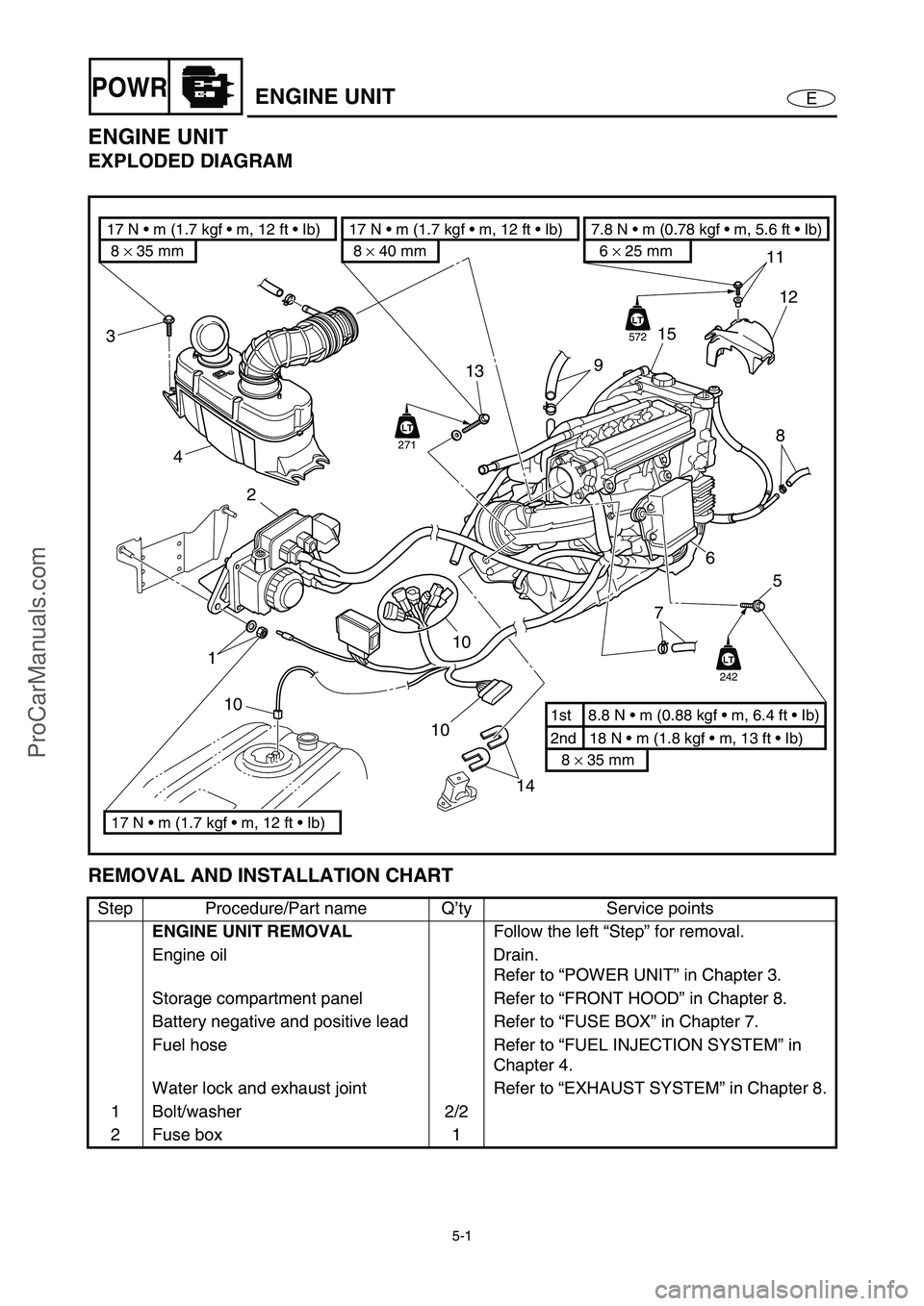
ENGINE UNIT
EXPLODED DIAGRAM
REMOVAL AND INSTALLATION CHART
Step Procedure/Part name Q’ty Service points
ENGINE UNIT REMOVAL
Follow the left “Step” for removal.
Engine oil Drain.
Refer to “POWER UNIT” in Chapter 3.
Storage compartment panel Refer to “FRONT HOOD” in Chapter 8.
Battery negative and positive lead Refer to “FUSE BOX” in Chapter 7.
Fuel hose Refer to “FUEL INJECTION SYSTEM” in
Chapter 4.
Water lock and exhaust joint Refer to “EXHAUST SYSTEM” in Chapter 8.
1 Bolt/washer 2/2
2 Fuse box 1
14 10
10
2
113
3
4
11
15
12
8
7
9
6
5
2nd 18 N m (1.8 kgf m, 13 ft Ib) 1st 8.8 N m (0.88 kgf m, 6.4 ft Ib)
8 × 35 mm
6 × 25 mm
7.8 N m (0.78 kgf m, 5.6 ft Ib)
8 × 35 mm 17 N m (1.7 kgf m, 12 ft Ib)
17 N m (1.7 kgf m, 12 ft Ib)8 × 40 mm
17 N m (1.7 kgf m, 12 ft Ib)
10LT
242
LT
LT
572
LT
LT
271
ProCarManuals.com