YAMAHA VX110 2005 Manual Online
Manufacturer: YAMAHA, Model Year: 2005, Model line: VX110, Model: YAMAHA VX110 2005Pages: 347, PDF Size: 14.17 MB
Page 81 of 347
4-4
EFUELFUEL TANK AND FUEL PUMP MODULE
SERVICE POINTS
Fuel hose disconnection
1. Disconnect:
Fuel hose
Refer to “FUEL INJECTION SYSTEM”.
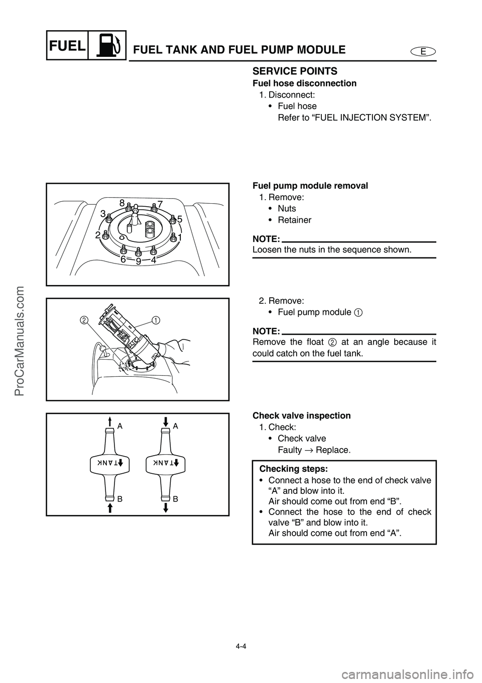
Fuel pump module removal
1. Remove:
Nuts
Retainer
NOTE:
Loosen the nuts in the sequence shown.
238
7
5
1 238
7
5
1
4 4
9 6 6
2. Remove:
Fuel pump module 1
NOTE:
Remove the float 2
at an angle because it
could catch on the fuel tank.
12
Check valve inspection
1. Check:
Check valve
Faulty →
Replace.
Checking steps:
Connect a hose to the end of check valve
“A” and blow into it.
Air should come out from end “B”.
Connect the hose to the end of check
valve “B” and blow into it.
Air should come out from end “A”.
A A
B B
ProCarManuals.com
Page 82 of 347
4-5
EFUELFUEL TANK AND FUEL PUMP MODULE
Fuel sender inspection
Refer to “FUEL CONTROL SYSTEM” in
Chapter 7.
Fuel tank inspection
1. Inspect:
Fuel tank
Cracks/damage →
Replace.
Fuel hose inspection
Refer to “FUEL INJECTION SYSTEM”.
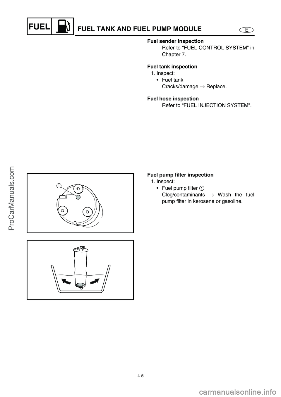
Fuel pump filter inspection
1. Inspect:
Fuel pump filter 1
Clog/contaminants →
Wash the fuel
pump filter in kerosene or gasoline.
1
ProCarManuals.com
Page 83 of 347
4-6
EFUEL
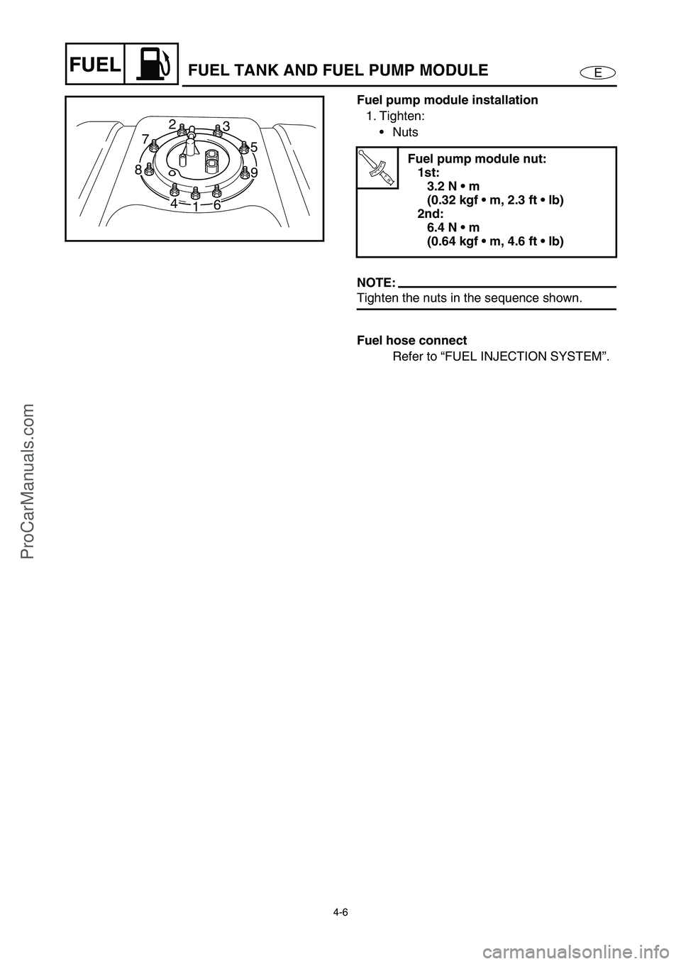
Fuel pump module installation
1. Tighten:
Nuts
NOTE:
Tighten the nuts in the sequence shown.
Fuel hose connect
Refer to “FUEL INJECTION SYSTEM”.
T R..
Fuel pump module nut:
1st:
3.2 N m
(0.32 kgf m, 2.3 ft lb)
2nd:
6.4 N m
(0.64 kgf m, 4.6 ft lb)238
7
5
1 872
3
5
9
4 6
1 6 4
FUEL TANK AND FUEL PUMP MODULE
ProCarManuals.com
Page 84 of 347
4-7
EFUELFUEL INJECTION SYSTEM
FUEL INJECTION SYSTEM
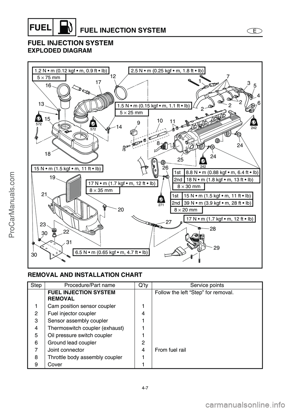
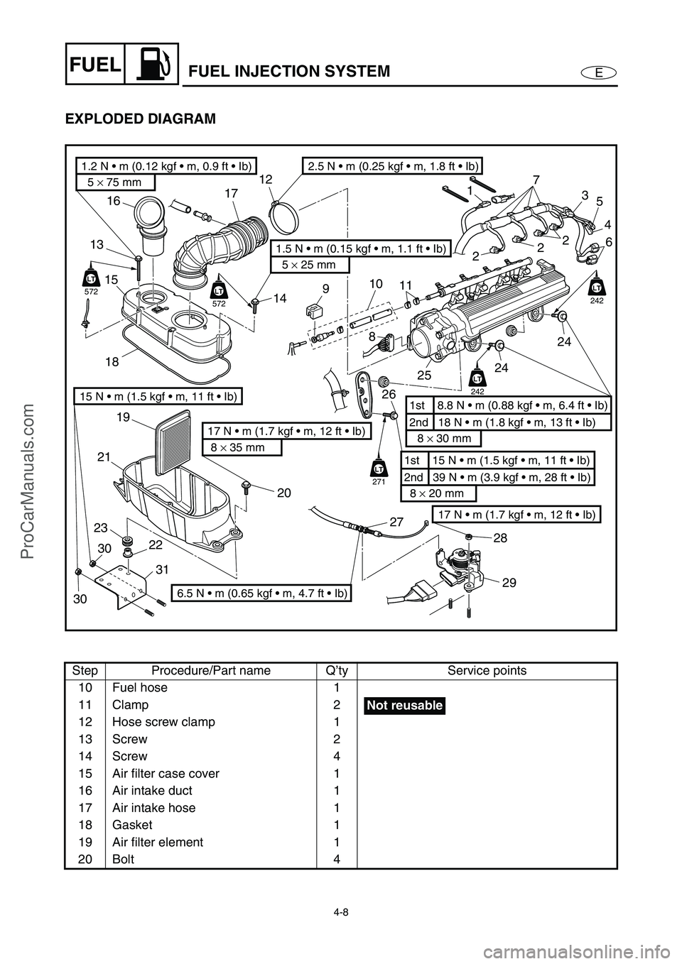
EXPLODED DIAGRAM
REMOVAL AND INSTALLATION CHART
Step Procedure/Part name Q’ty Service points
FUEL INJECTION SYSTEM
REMOVALFollow the left “Step” for removal.
1 Cam position sensor coupler 1
2 Fuel injector coupler 4
3 Sensor assembly coupler 1
4 Thermoswitch coupler (exhaust) 1
5 Oil pressure switch coupler 1
6 Ground lead coupler 2
7 Joint connector 4 From fuel rail
8 Throttle body assembly coupler 1
9 Cover 1
17 N m (1.7 kgf m, 12 ft Ib)
5 × 75 mm
1.2 N m (0.12 kgf m, 0.9 ft Ib)
5 × 25 mm
1.5 N m (0.15 kgf m, 1.1 ft Ib)
8 × 35 mm
17 N m (1.7 kgf m, 12 ft Ib)2nd 18 N m (1.8 kgf m, 13 ft Ib) 1st 8.8 N m (0.88 kgf m, 6.4 ft Ib)
8 × 30 mm
2nd 39 N m (3.9 kgf m, 28 ft Ib) 1st 15 N m (1.5 kgf m, 11 ft Ib)
8 × 20 mm
LT
242
LT
242
LT
271
LT
572
LT
LT
572
LT
22 2320 19
2118 15 1316
14 1712
17
3
2
2
25
4
6
24
24
25 8
26
27
28
29
11 10
9
2.5 N m (0.25 kgf m, 1.8 ft Ib)
6.5 N m (0.65 kgf m, 4.7 ft Ib)
15 N m (1.5 kgf m, 11 ft Ib)
3031
30
ProCarManuals.com
Page 85 of 347
4-8
EFUELFUEL INJECTION SYSTEM
EXPLODED DIAGRAM
Step Procedure/Part name Q’ty Service points
10 Fuel hose 1
11 Clamp 2
12 Hose screw clamp 1
13 Screw 2
14 Screw 4
15 Air filter case cover 1
16 Air intake duct 1
17 Air intake hose 1
18 Gasket 1
19 Air filter element 1
20 Bolt 4
17 N m (1.7 kgf m, 12 ft Ib)
5 × 75 mm
1.2 N m (0.12 kgf m, 0.9 ft Ib)
5 × 25 mm
1.5 N m (0.15 kgf m, 1.1 ft Ib)
8 × 35 mm
17 N m (1.7 kgf m, 12 ft Ib)2nd 18 N m (1.8 kgf m, 13 ft Ib) 1st 8.8 N m (0.88 kgf m, 6.4 ft Ib)
8 × 30 mm
2nd 39 N m (3.9 kgf m, 28 ft Ib) 1st 15 N m (1.5 kgf m, 11 ft Ib)
8 × 20 mm
LT
242
LT
242
LT
271
LT
572
LT
LT
572
LT
22 2320 19
2118 15 1316
14 1712
17
3
2
2
25
4
6
24
24
25 8
26
27
28
29
11 10
9
2.5 N m (0.25 kgf m, 1.8 ft Ib)
6.5 N m (0.65 kgf m, 4.7 ft Ib)
15 N m (1.5 kgf m, 11 ft Ib)
3031
30
Not reusable
ProCarManuals.com
Page 86 of 347
4-9
EFUELFUEL INJECTION SYSTEM
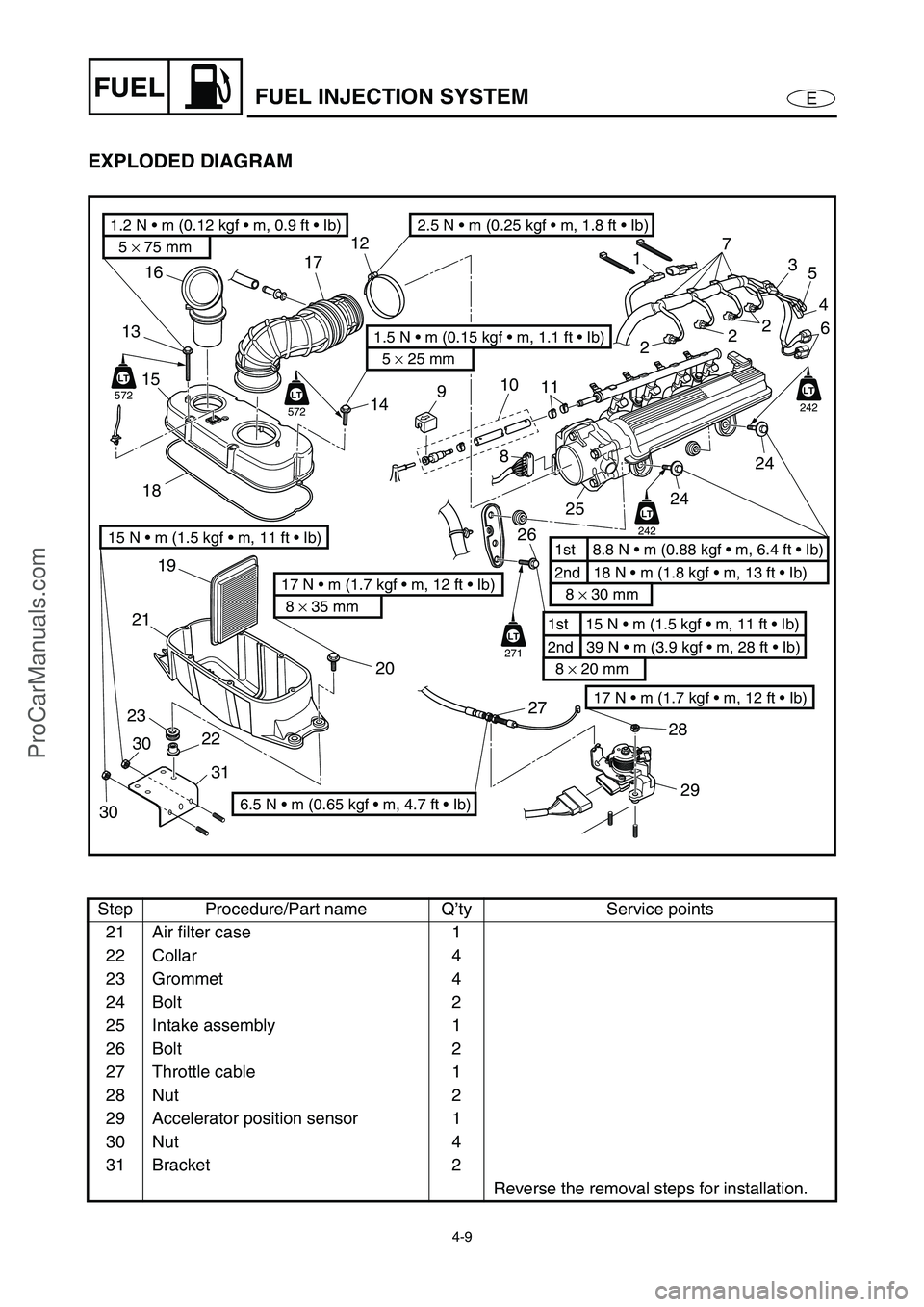
EXPLODED DIAGRAM
Step Procedure/Part name Q’ty Service points
21 Air filter case 1
22 Collar 4
23 Grommet 4
24 Bolt 2
25 Intake assembly 1
26 Bolt 2
27 Throttle cable 1
28 Nut 2
29 Accelerator position sensor 1
30 Nut 4
31 Bracket 2
Reverse the removal steps for installation.
17 N m (1.7 kgf m, 12 ft Ib)
5 × 75 mm
1.2 N m (0.12 kgf m, 0.9 ft Ib)
5 × 25 mm
1.5 N m (0.15 kgf m, 1.1 ft Ib)
8 × 35 mm
17 N m (1.7 kgf m, 12 ft Ib)2nd 18 N m (1.8 kgf m, 13 ft Ib) 1st 8.8 N m (0.88 kgf m, 6.4 ft Ib)
8 × 30 mm
2nd 39 N m (3.9 kgf m, 28 ft Ib) 1st 15 N m (1.5 kgf m, 11 ft Ib)
8 × 20 mm
LT
242
LT
242
LT
271
LT
572
LT
LT
572
LT
22 2320 19
2118 15 1316
14 1712
17
3
2
2
25
4
6
24
24
25 8
26
27
28
29
11 10
9
2.5 N m (0.25 kgf m, 1.8 ft Ib)
6.5 N m (0.65 kgf m, 4.7 ft Ib)
15 N m (1.5 kgf m, 11 ft Ib)
3031
30
ProCarManuals.com
Page 87 of 347
4-10
EFUEL
THROTTLE BODY ASSEMBLY AND INTAKE
MANIFOLD
THROTTLE BODY ASSEMBLY AND INTAKE MANIFOLD
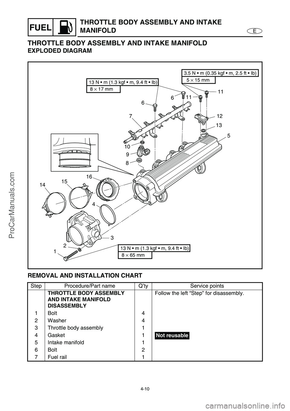
EXPLODED DIAGRAM
REMOVAL AND INSTALLATION CHART
Step Procedure/Part name Q’ty Service points
THROTTLE BODY ASSEMBLY
AND INTAKE MANIFOLD
DISASSEMBLYFollow the left “Step” for disassembly.
1Bolt 4
2 Washer 4
3 Throttle body assembly 1
4Gasket 1
5 Intake manifold 1
6Bolt 2
7 Fuel rail 1
8 × 17 mm
13 N m (1.3 kgf m, 9.4 ft Ib)5 × 15 mm
3.5 N m (0.35 kgf m, 2.5 ft Ib)
8 × 65 mm
13 N m (1.3 kgf m, 9.4 ft Ib)123 4 14151689 107661111
12
13
5
Not reusable
ProCarManuals.com
Page 88 of 347

4-11
EFUEL
THROTTLE BODY ASSEMBLY AND INTAKE
MANIFOLD
EXPLODED DIAGRAM
Step Procedure/Part name Q’ty Service points
8Gasket 4
9 Fuel injector 4
10 O-ring 4
11 Screw 2
12 Sensor assembly 1
13 O-ring 1
14 Clamp 4
15 Clamp 4
16 Intake manifold joint 4
Reverse the disassembly steps for
assembly.
8 × 17 mm
13 N m (1.3 kgf m, 9.4 ft Ib)5 × 15 mm
3.5 N m (0.35 kgf m, 2.5 ft Ib)
8 × 65 mm
13 N m (1.3 kgf m, 9.4 ft Ib)123 4 14151689 107661111
12
13
5
Not reusable
Not reusable
Not reusable
ProCarManuals.com
Page 89 of 347

4-12
EFUEL
THROTTLE BODY ASSEMBLY AND INTAKE
MANIFOLD
SERVICE POINTS
Fuel hose clamps removal
1. Remove:
Fuel hose clamps
CAUTION:
If the fuel hose clamps are removed with-
out cutting the joint first, the fuel hose will
be damaged.
Hose clamps installation
1. Install:
Fuel hose clamps
WARNING
Do not reuse the fuel hose clamps, always
replace them with new ones.
NOTE:
Crimp the fuel hose clamps properly to
securely fasten them.
Fuel hose disconnection
WARNING
Before disconnecting the hose, remove the
fuel tank filler cap to reduce any pressure
inside the fuel tank, and then disconnect
the battery negative lead to cut off the elec-
tric current to the electrical systems.
1. Wrap the quick connector with a cloth, and
then rotate the quick connector tab 1
to
the stopper position a
.
WARNING
If the quick connector is removed sud-
denly, pressurized fuel could spray out. To
gradually release the fuel pressure, be sure
to remove the quick connector slowly.
1
a
ProCarManuals.com
Page 90 of 347

4-13
EFUEL
CAUTION:
Do not rotate the quick connector tab
1
past the stopper position, otherwise it
could be damaged.
When the fuel hoses are disconnected,
quickly remove the retainer
2 from the
quick connector, otherwise the retainer
could be lost.
2. Disconnect the fuel hose 1
from the fuel
pipe 2
directly.
WARNING
Always reduce the fuel pressure in the fuel
line before servicing the line or the fuel
pipe. If the fuel pressure is not released,
pressurized fuel could spray out.
21
1
2
3. Cover the quick connector and fuel pipe
with a plastic bag 3 to prevent damage
and to protect them from dirt.
3
Fuel line inspection
1. Inspect:
Fuel hose
Damage/cracks → Replace.
O-rings (quick connector)
Damage/cracks → Replace the quick
connector.
Fuel pipe
Damage/cracks → Replace the fuel
pump.
THROTTLE BODY ASSEMBLY AND INTAKE
MANIFOLD
ProCarManuals.com