YAMAHA VX110 2005 Service Manual
VX110 2005
YAMAHA
YAMAHA
https://www.carmanualsonline.info/img/51/57494/w960_57494-0.png
YAMAHA VX110 2005 Service Manual
Trending: fuel pump, key, check engine light, remote control, jump start, fuses, wiring diagram
Page 131 of 347
5-32
EPOWRREDUCTION DRIVE GEAR
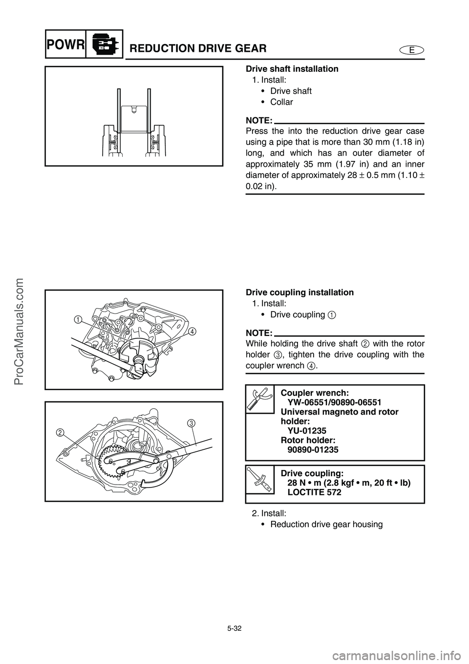
Drive shaft installation
1. Install:
Drive shaft
Collar
NOTE:
Press the into the reduction drive gear case
using a pipe that is more than 30 mm (1.18 in)
long, and which has an outer diameter of
approximately 35 mm (1.97 in) and an inner
diameter of approximately 28 ±
0.5 mm (1.10 ±
0.02 in).
Drive coupling installation
1. Install:
Drive coupling 1
NOTE:
While holding the drive shaft 2
with the rotor
holder 3
, tighten the drive coupling with the
coupler wrench 4
.
2. Install:
Reduction drive gear housing
Coupler wrench:
YW-06551/90890-06551
Universal magneto and rotor
holder:
YU-01235
Rotor holder:
90890-01235
T R..
Drive coupling:
28 N m (2.8 kgf m, 20 ft lb)
LOCTITE 572
1
4
23
ProCarManuals.com
Page 132 of 347
5-33
EPOWRGENERATOR AND STARTER MOTOR
GENERATOR AND STARTER MOTOR
EXPLODED DIAGRAM
REMOVAL AND INSTALLATION CHART
Step Procedure/Part name Q’ty Service points
GENERATOR COVER AND
FLYWHEEL MAGNETO
REMOVALFollow the left “Step” for removal.
Engine unit Refer to “ENGINE UNIT”.
1 Nut/washer 1/1
2 Starter motor lead 1
3Bolt 2
4 Battery negative lead 1
5 Starter motor 1
6 Band 1
7 Lighting coil coupler 1
4 3
2 1
5
7
89
1113 12
18 16171920 21
15 14
AA
E
E
E
LT
572
LT
572
AA
AA
8 × 30 mm
18 N m (1.8 kgf
m, 13 ft
Ib)
4.9 N
m (0.49 kgf m, 3.5 ft Ib)
10 × 47 mm
75 N m (7.5 kgf
m, 54 ft
Ib) 8 × 20 mm
24 N m (2.4 kgf
m, 17 ft
Ib)
10 × 60 mm
2nd 50 N m (5.0 kgf
m, 36 ft
Ib) 1st 15 N m (1.5 kgf
m, 11 ft
Ib)
6
2nd 50 N m (5.0 kgf
m, 36 ft
Ib) 1st 15 N m (1.5 kgf m, 11 ft Ib)
10 × 135 mm
10
LT
572
LT
572
ProCarManuals.com
Page 133 of 347
5-34
EPOWRGENERATOR AND STARTER MOTOR
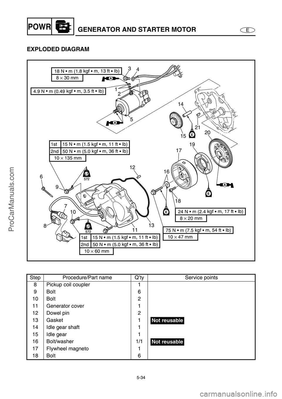
EXPLODED DIAGRAM
Step Procedure/Part name Q’ty Service points
8 Pickup coil coupler 1
9Bolt 6
10 Bolt 2
11 Generator cover 1
12 Dowel pin 2
13 Gasket 1
14 Idle gear shaft 1
15 Idle gear 1
16 Bolt/washer 1/1
17 Flywheel magneto 1
18 Bolt 6
4 3
2 1
5
7
89
1113 12
18 16171920 21
15 14
AA
E
E
E
LT
572
LT
572
AA
AA
8 × 30 mm
18 N m (1.8 kgf
m, 13 ft
Ib)
4.9 N
m (0.49 kgf m, 3.5 ft Ib)
10 × 47 mm
75 N m (7.5 kgf
m, 54 ft
Ib) 8 × 20 mm
24 N m (2.4 kgf
m, 17 ft
Ib)
10 × 60 mm
2nd 50 N m (5.0 kgf
m, 36 ft
Ib) 1st 15 N m (1.5 kgf
m, 11 ft
Ib)
6
2nd 50 N m (5.0 kgf
m, 36 ft
Ib) 1st 15 N m (1.5 kgf m, 11 ft Ib)
10 × 135 mm
10
LT
572
LT
572
Not reusable
Not reusable
ProCarManuals.com
Page 134 of 347
5-35
EPOWRGENERATOR AND STARTER MOTOR
EXPLODED DIAGRAM
Step Procedure/Part name Q’ty Service points
19 Starter clutch 1
20 Starter gear 1
21 Woodruff key 1
Reverse the removal steps for installation.
4 3
2 1
5
7
89
1113 12
18 16171920 21
15 14
AA
E
E
E
LT
572
LT
572
AA
AA
8 × 30 mm
18 N m (1.8 kgf
m, 13 ft
Ib)
4.9 N
m (0.49 kgf m, 3.5 ft Ib)
10 × 47 mm
75 N m (7.5 kgf
m, 54 ft
Ib) 8 × 20 mm
24 N m (2.4 kgf
m, 17 ft
Ib)
10 × 60 mm
2nd 50 N m (5.0 kgf
m, 36 ft
Ib) 1st 15 N m (1.5 kgf
m, 11 ft
Ib)
6
2nd 50 N m (5.0 kgf
m, 36 ft
Ib) 1st 15 N m (1.5 kgf m, 11 ft Ib)
10 × 135 mm
10
LT
572
LT
572
ProCarManuals.com
Page 135 of 347
5-36
EPOWRGENERATOR AND STARTER MOTOR
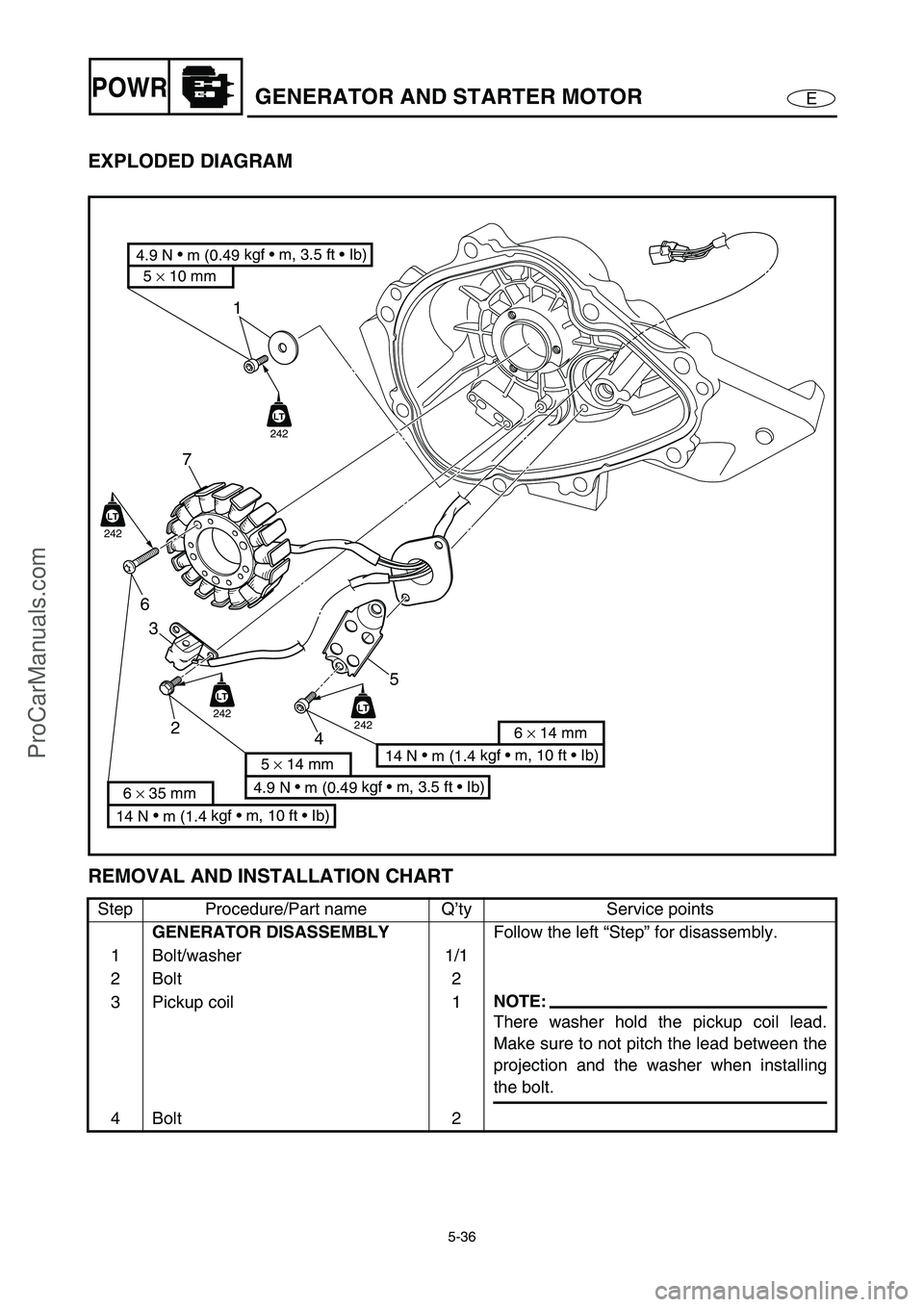
EXPLODED DIAGRAM
REMOVAL AND INSTALLATION CHART
Step Procedure/Part name Q’ty Service points
GENERATOR DISASSEMBLY
Follow the left “Step” for disassembly.
1 Bolt/washer 1/1
2Bolt 2
3 Pickup coil 1
NOTE:
There washer hold the pickup coil lead.
Make sure to not pitch the lead between the
projection and the washer when installing
the bolt.
4Bolt 2
1
7
6
3
2
45
LT
242
LT
242
LT
242LT
242
14 N
m (1.4 kgf m, 10 ft Ib)
6 × 14 mm
4.9 N
m (0.49 kgf m, 3.5 ft Ib)
5 × 14 mm
14 N
m (1.4 kgf m, 10 ft Ib)
6 × 35 mm
4.9 N
m (0.49 kgf m, 3.5 ft Ib)
5 × 10 mm
ProCarManuals.com
Page 136 of 347
5-37
EPOWRGENERATOR AND STARTER MOTOR
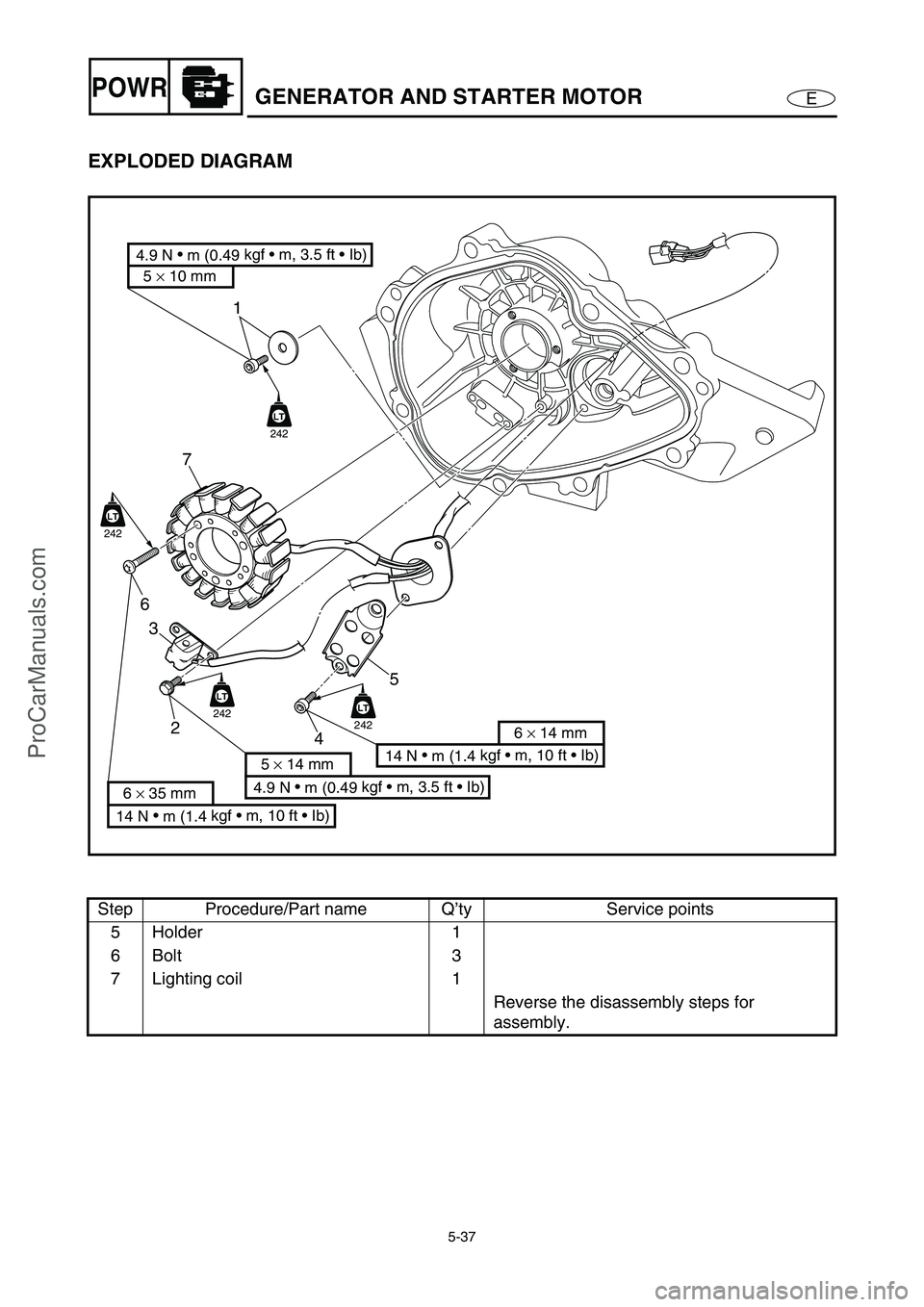
EXPLODED DIAGRAM
Step Procedure/Part name Q’ty Service points
5 Holder 1
6Bolt 3
7 Lighting coil 1
Reverse the disassembly steps for
assembly.
1
7
6
3
2
45
LT
242
LT
242
LT
242LT
242
14 N
m (1.4 kgf m, 10 ft Ib)
6 × 14 mm
4.9 N
m (0.49 kgf m, 3.5 ft Ib)
5 × 14 mm
14 N
m (1.4 kgf m, 10 ft Ib)
6 × 35 mm
4.9 N
m (0.49 kgf m, 3.5 ft Ib)
5 × 10 mm
ProCarManuals.com
Page 137 of 347
5-38
EPOWRGENERATOR AND STARTER MOTOR
SERVICE POINTS
Flywheel magneto removal
1. Remove:
Flywheel magneto bolt 1
Washer
NOTE:
While holding the flywheel magneto 2
with the
sheave holder 3
, loosen the flywheel magneto
bolt.
Sheave holder:
YS-01880-A/90890-01701
2. Remove:
Flywheel magneto 1
Woodruff key
NOTE:
While holding the flywheel magneto with
sheave holder 2
, remove the flywheel mag-
neto with the rotor puller 3
.
Rotor puller:
YM-01082/90890-01080
Starter clutch inspection
1. Check:
Starter clutch rollers 1
Damage/wear →
Replace.
ProCarManuals.com
Page 138 of 347
5-39
EPOWRGENERATOR AND STARTER MOTOR
2. Check:
Starter clutch 1
Starter gear 2
Burrs/chips/roughness/wear →
Replace
the defective part(s).
3. Check:
Starter clutch gear’s contacting surfaces
a
Damage/pitting/wear →
Replace the
starter clutch gear.
12
a
4. Check:
Starter clutch operation
Checking steps:
Install the starter gear 1
onto the starter
clutch 2
and hold the starter clutch.
When turning the starter gear clockwise
È, it should turn freely, otherwise the
starter clutch is faulty and must be
replaced.
When turning the starter gear counter-
clockwise É, the starter clutch and the
starter gear should engage, otherwise
the starter clutch is faulty and must be
replaced.
ProCarManuals.com
Page 139 of 347
5-40
EPOWRGENERATOR AND STARTER MOTOR
Flywheel magneto installation
1. Install:
Woodruff key
Flywheel magneto
Washer
Flywheel magneto bolt
NOTE:
Clean the tapered portion of the crankshaft
and the flywheel magneto hub.
When installing the flywheel magneto, make
sure the woodruff key is properly seated in
the keyway of the crankshaft.
Lubricate the flywheel magneto bolt and
washer with engine oil.
2. Tighten:
Flywheel magneto bolt 1
NOTE:
While holding the flywheel magneto 2
with the
sheave holder 3
, tighten the flywheel mag-
neto bolt.
CAUTION:
Do not reuse the flywheel magneto bolt and
washer, always replace them with new
ones.
T R..
Flywheel magneto bolt:
75 N m (7.5 kgf m, 54 ft lb)
Sheave holder:
YS-01880-A/90890-01701
ProCarManuals.com
Page 140 of 347
5-41
EPOWRCAMSHAFTS
CAMSHAFTS
EXPLODED DIAGRAM
REMOVAL AND INSTALLATION CHART
Step Procedure/Part name Q’ty Service points
CYLINDER HEAD COVER
REMOVALFollow the left “Step” for removal.
1Bolt 4
2 Ignition coil 4
3 Spark plug 4
4 Clamp/breather hose 1/1È
To oil tank
Paint mark a
5Bolt 1
6 Cam position sensor 1
7 Clamp/cooling water hose 1/1É
To transom plate
8 Rubber seal 1
E
4
65
7 8
10
11
12
13 9
LT
572
LT
14
16
15
3
13 N
m (1.3 kgf m, 9.4 ft Ib)
10 N
m (1.0 kgf m, 7.2 ft Ib)
6 × 16 mm 6 × 16 mm
2nd 7.6 N m (0.76 kgf
m, 5.5 ft
Ib) 1st 3.7 N m (0.37 kgf
m, 2.7 ft
Ib)
12 N
m (1.2 kgf m, 8.7 ft Ib)
6 × 22 mm
aÈ
É
1
2
7.6 N
m (0.76 kgf m, 5.5 ft Ib)
6 × 16 mm
LT
572
LTAA
1280B
1280B
ProCarManuals.com
Trending: service interval, torque, fuse diagram, cooling, width, ad blue, remote start


