YAMAHA VX110 2005 Service Manual
Manufacturer: YAMAHA, Model Year: 2005, Model line: VX110, Model: YAMAHA VX110 2005Pages: 347, PDF Size: 14.17 MB
Page 141 of 347
5-42
EPOWRCAMSHAFTS
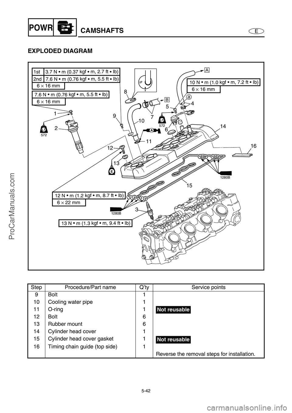
EXPLODED DIAGRAM
Step Procedure/Part name Q’ty Service points
9Bolt 1
10 Cooling water pipe 1
11 O-ring 1
12 Bolt 6
13 Rubber mount 6
14 Cylinder head cover 1
15 Cylinder head cover gasket 1
16 Timing chain guide (top side) 1
Reverse the removal steps for installation.
E
4
65
7 8
10
11
12
13 9
LT
572
LT
14
16
15
3
13 N
m (1.3 kgf m, 9.4 ft Ib)
10 N
m (1.0 kgf m, 7.2 ft Ib)
6 × 16 mm 6 × 16 mm
2nd 7.6 N m (0.76 kgf
m, 5.5 ft
Ib) 1st 3.7 N m (0.37 kgf
m, 2.7 ft
Ib)
12 N
m (1.2 kgf m, 8.7 ft Ib)
6 × 22 mm
aÈ
É
1
2
7.6 N
m (0.76 kgf m, 5.5 ft Ib)
6 × 16 mm
LT
572
LTAA
1280B
1280B
Not reusable
Not reusable
ProCarManuals.com
Page 142 of 347

5-43
EPOWRCAMSHAFTS
EXPLODED DIAGRAM
REMOVAL AND INSTALLATION CHART
Step Procedure/Part name Q’ty Service points
CAMSHAFT REMOVAL
Follow the left “Step” for removal.
Cylinder head cover
Reduction drive gear case Refer to “REDUCTION DRIVE GEAR”.
NOTE:
When removing camshafts it is not neces-
sary to remove the reduction drive gear
case.
1 Thermoswitch (engine) coupler 1
2 Engine temperature sensor coupler 1
3 Cap bolt 1
4Gasket 1
5Bolt 2
M
E
EE
E
E
E
M
12
13
12
13
12
13
141819
10
20
10
10
15
11
16
9
17
822
21
3 4
5 6 7
10 N
m (1.0 kgf m, 7.2 ft Ib)
6 × 35 mm
10 N
m (1.0 kgf m, 7.2 ft Ib)
6 × 35 mm
10 N
m (1.0 kgf m, 7.2 ft Ib)
6 × 25 mm
10 N
m (1.0 kgf m, 7.2 ft Ib)
6 × 8 mm
24 N
m (2.4 kgf m, 17 ft Ib)
7 × 11 mm
24 N
m (2.4 kgf m, 17 ft Ib)
7 × 11 mm
2324
25
26
27
12
6 × 16 mm
AA
Not reusable
ProCarManuals.com
Page 143 of 347

5-44
EPOWRCAMSHAFTS
EXPLODED DIAGRAM
Step Procedure/Part name Q’ty Service points
6 Timing chain tensioner 1
7 Timing chain tensioner gasket 1
8 Timing chain guide (exhaust side) 1
9Bolt 18
10 Intake camshaft cap 3
11 Dowel pin 6
12 Bolt 10
13 Exhaust camshaft cap 3
14 Dowel pin 6
15 Intake camshaft 1
16 Bolt 2
17 Intake camshaft sprocket 1
M
E
EE
E
E
E
M
12
13
12
13
12
13
141819
10
20
10
10
15
11
16
9
17
822
21
3 4
5 6 7
10 N •
m (1.0 kgf m, 7.2 ft Ib)
6 × 35 mm
10 N
m (1.0 kgf m, 7.2 ft Ib)
6 × 35 mm
10 N
m (1.0 kgf m, 7.2 ft Ib)
6 × 25 mm
10 N
m (1.0 kgf m, 7.2 ft Ib)
6 × 8 mm
24 N
m (2.4 kgf m, 17 ft Ib)
7 × 11 mm
24 N
m (2.4 kgf m, 17 ft Ib)
7 × 11 mm
2324
25
26
27
12
6 × 16 mm
AA
Not reusable
ProCarManuals.com
Page 144 of 347
5-45
EPOWRCAMSHAFTS
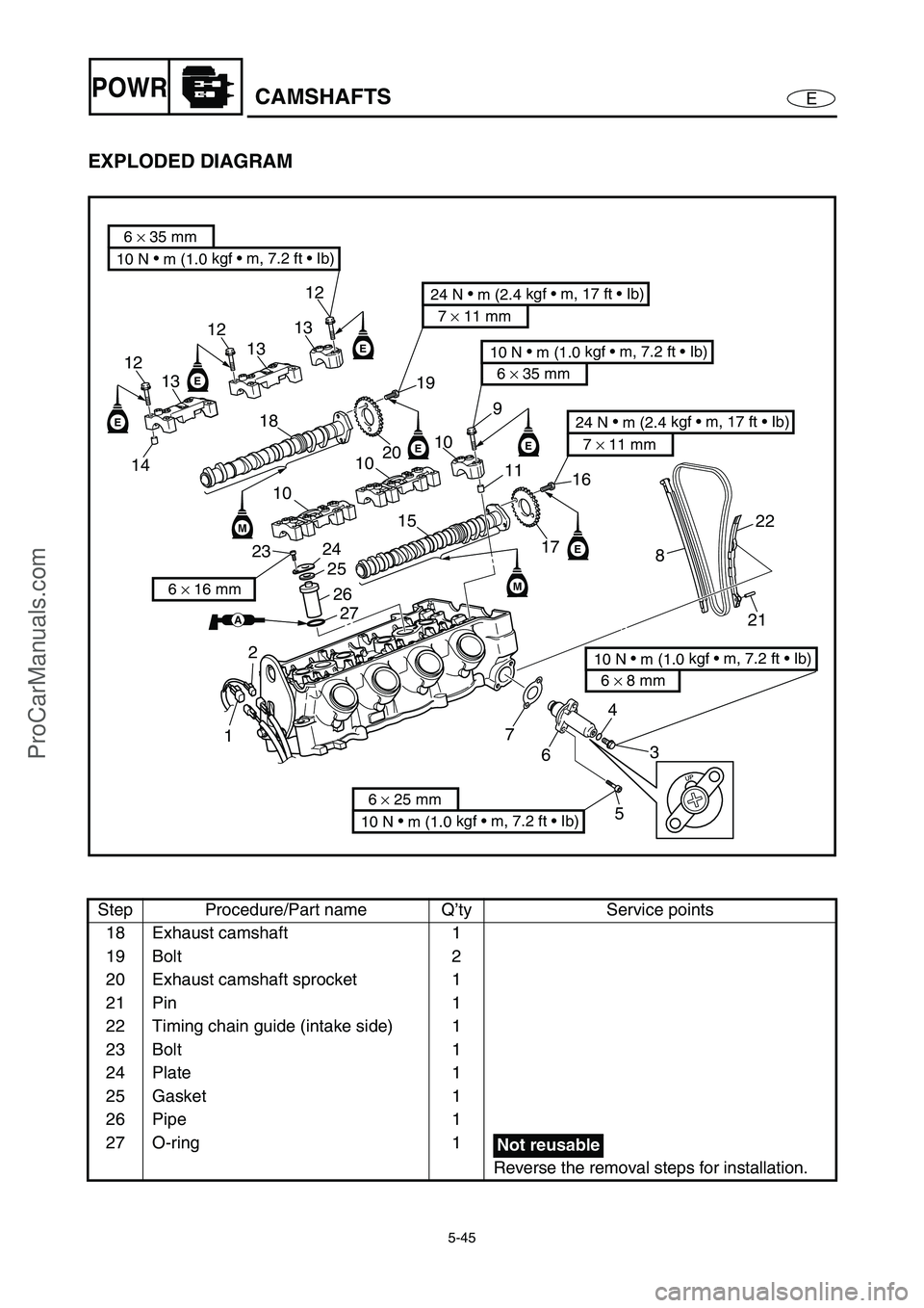
EXPLODED DIAGRAM
Step Procedure/Part name Q’ty Service points
18 Exhaust camshaft 1
19 Bolt 2
20 Exhaust camshaft sprocket 1
21 Pin 1
22 Timing chain guide (intake side) 1
23 Bolt 1
24 Plate 1
25 Gasket 1
26 Pipe 1
27 O-ring 1
Reverse the removal steps for installation.
M
E
EE
E
E
E
M
12
13
12
13
12
13
141819
10
20
10
10
15
11
16
9
17
822
21
3 4
5 6 7
10 N
m (1.0 kgf m, 7.2 ft Ib)
6 × 35 mm
10 N
m (1.0 kgf m, 7.2 ft Ib)
6 × 35 mm
10 N
m (1.0 kgf m, 7.2 ft Ib)
6 × 25 mm
10 N
m (1.0 kgf m, 7.2 ft Ib)
6 × 8 mm
24 N
m (2.4 kgf m, 17 ft Ib)
7 × 11 mm
24 N
m (2.4 kgf m, 17 ft Ib)
7 × 11 mm
2324
25
26
27
12
6 × 16 mm
AA
Not reusable
ProCarManuals.com
Page 145 of 347

5-46
EPOWRCAMSHAFTS
SERVICE POINTS
Camshaft removal
1. Install:
Dial gauge needle
Dial gauge stand 1
(into spark plug hole #1)
Dial gauge 2
2. Turn the drive coupling counterclockwise,
and then check if cylinder #1 is at TDC of
the compression stroke with a dial gauge.
NOTE:
TDC on the compression stroke can be found
when the camshaft lobes are turned away from
each other.
Dial gauge stand:
90890-06583
Dial gauge needle:
90890-06584
Dial gauge stand set:
YB-06585/90890-06585
Dial indicator gauge:
YU-03097
Dial gauge set:
90890-01252
2
1
INEX
3. Make the alignment marks a on the timing
chain and camshaft sprockets.
a
4. Remove:
Timing chain tensioner 1
Gasket
1
ProCarManuals.com
Page 146 of 347
5-47
EPOWRCAMSHAFTS
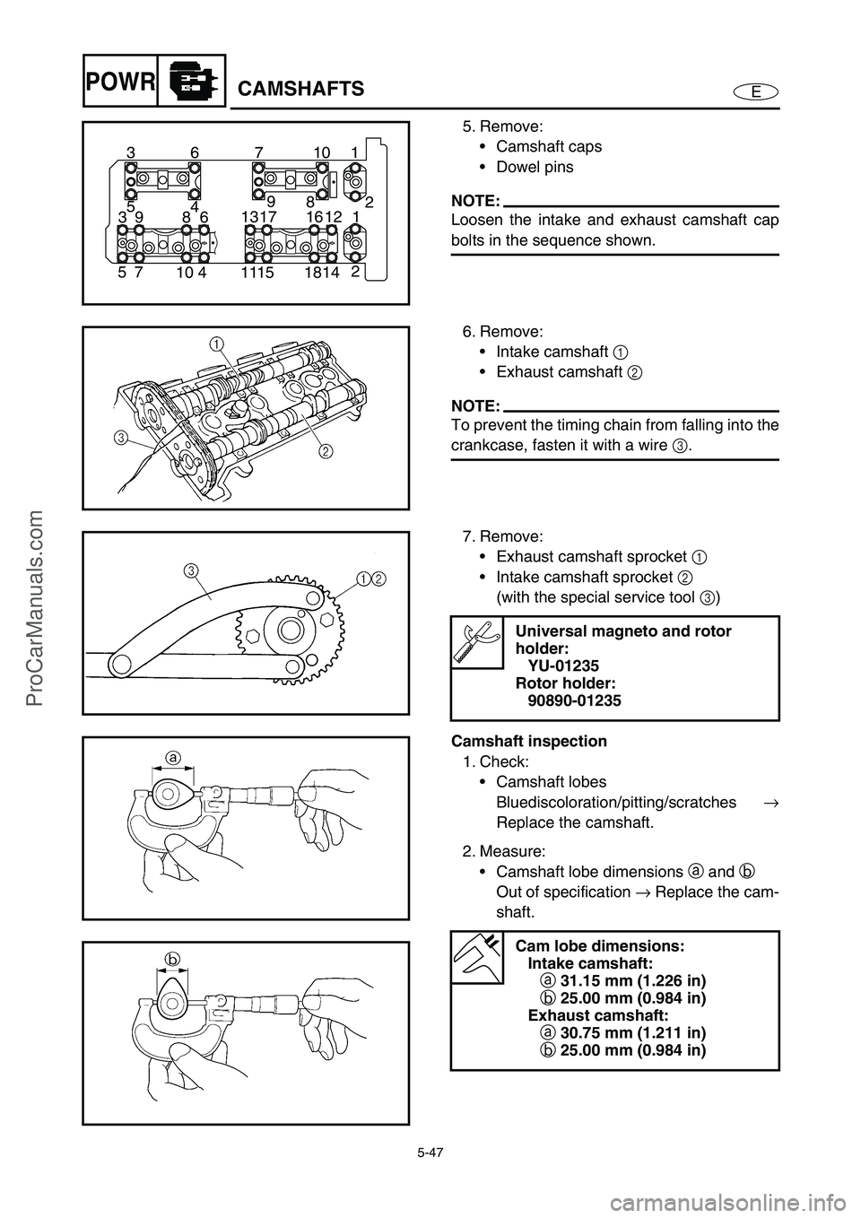
5. Remove:
Camshaft caps
Dowel pins
NOTE:
Loosen the intake and exhaust camshaft cap
bolts in the sequence shown.
1 10 7 6 3
2
14 18 15 11 4 10 7 52 8 9
4 5
1 12 16 17 13
6 8 9 3
6. Remove:
Intake camshaft 1
Exhaust camshaft 2
NOTE:
To prevent the timing chain from falling into the
crankcase, fasten it with a wire 3
.
7. Remove:
Exhaust camshaft sprocket 1
Intake camshaft sprocket 2
(with the special service tool 3
)
Universal magneto and rotor
holder:
YU-01235
Rotor holder:
90890-01235
Camshaft inspection
1. Check:
Camshaft lobes
Bluediscoloration/pitting/scratches →
Replace the camshaft.
2. Measure:
Camshaft lobe dimensions a
and b
Out of specification →
Replace the cam-
shaft.
Cam lobe dimensions:
Intake camshaft:
a 31.15 mm (1.226 in)
b 25.00 mm (0.984 in)
Exhaust camshaft:
a 30.75 mm (1.211 in)
b 25.00 mm (0.984 in)
ProCarManuals.com
Page 147 of 347
5-48
EPOWRCAMSHAFTS
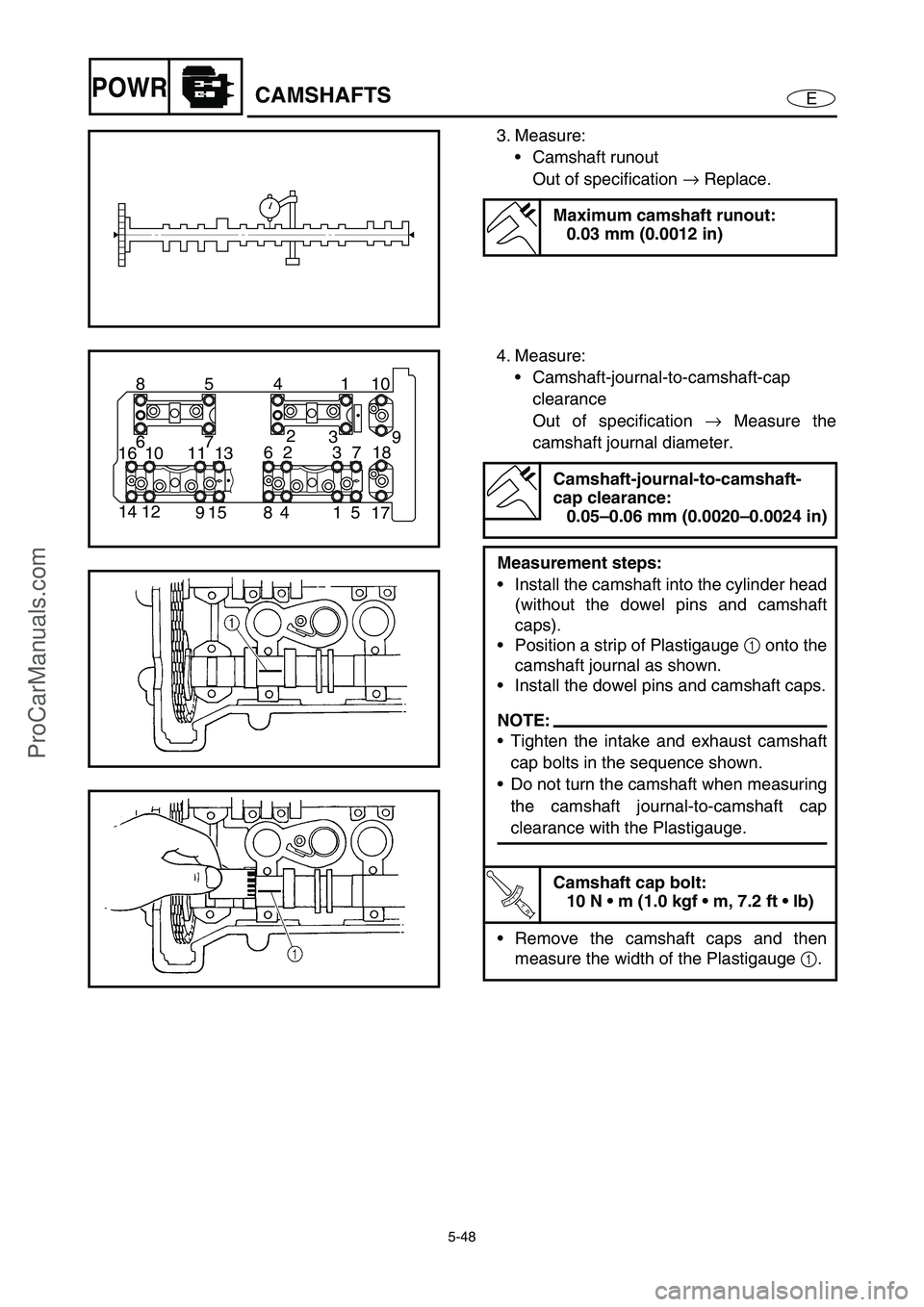
3. Measure:
Camshaft runout
Out of specification →
Replace.
Maximum camshaft runout:
0.03 mm (0.0012 in)
4. Measure:
Camshaft-journal-to-camshaft-cap
clearance
Out of specification →
Measure the
camshaft journal diameter.
Camshaft-journal-to-camshaft-
cap clearance:
0.05–0.06 mm (0.0020–0.0024 in)
Measurement steps:
Install the camshaft into the cylinder head
(without the dowel pins and camshaft
caps).
Position a strip of Plastigauge 1
onto the
camshaft journal as shown.
Install the dowel pins and camshaft caps.
NOTE:
Tighten the intake and exhaust camshaft
cap bolts in the sequence shown.
Do not turn the camshaft when measuring
the camshaft journal-to-camshaft cap
clearance with the Plastigauge.
T R..
Camshaft cap bolt:
10 N m (1.0 kgf m, 7.2 ft lb)
Remove the camshaft caps and then
measure the width of the Plastigauge 1
.
10 1 4 5 8
17 5 1 4 8 15 9 12 149 3 2
7 6
18 7 3 2 6
13 11 10 16
ProCarManuals.com
Page 148 of 347
5-49
EPOWRCAMSHAFTS
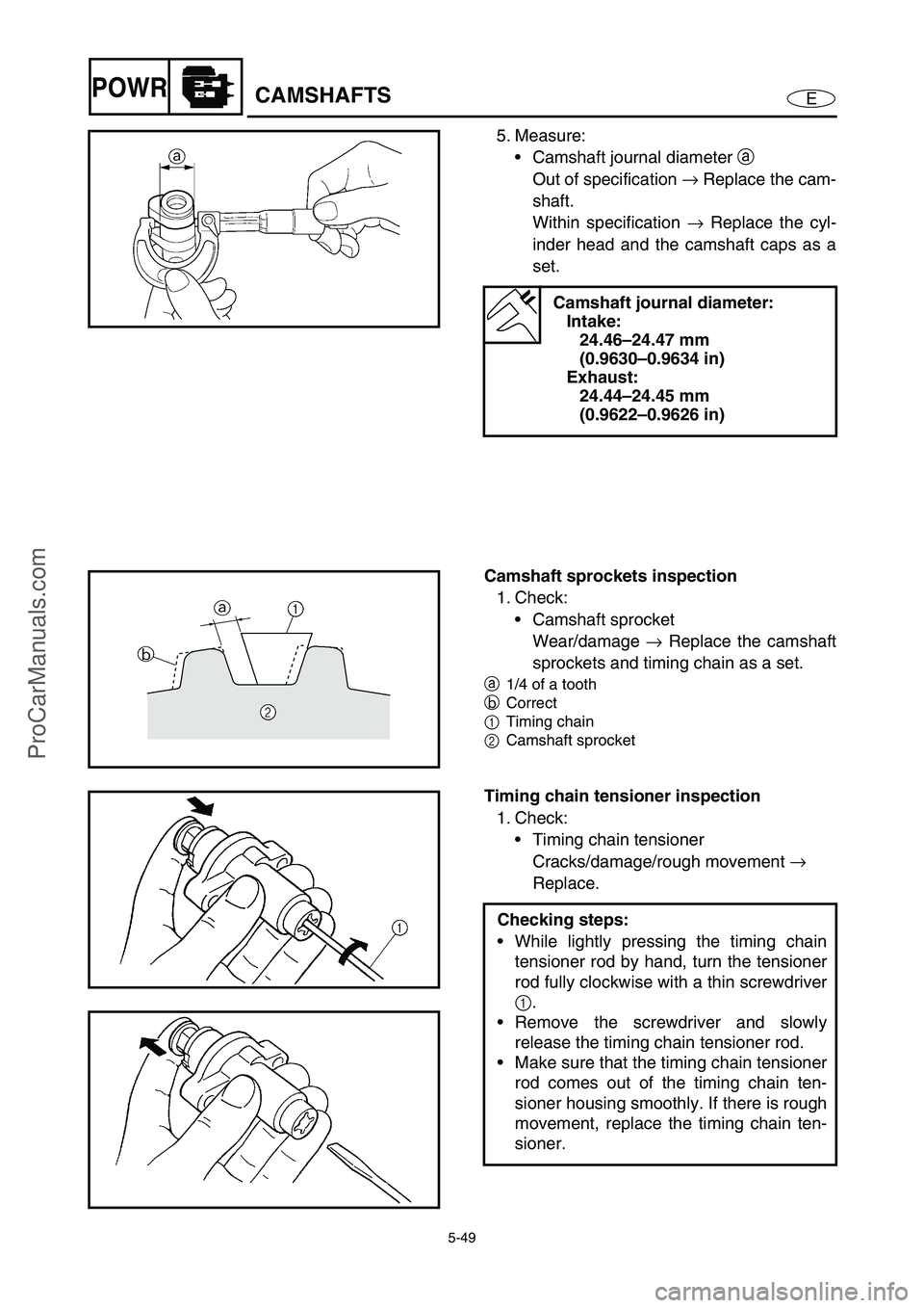
5. Measure:
Camshaft journal diameter a
Out of specification →
Replace the cam-
shaft.
Within specification →
Replace the cyl-
inder head and the camshaft caps as a
set.
Camshaft journal diameter:
Intake:
24.46–24.47 mm
(0.9630–0.9634 in)
Exhaust:
24.44–24.45 mm
(0.9622–0.9626 in)
Camshaft sprockets inspection
1. Check:
Camshaft sprocket
Wear/damage →
Replace the camshaft
sprockets and timing chain as a set.
a
1/4 of a tooth
b
Correct
1Timing chain
2Camshaft sprocket
Timing chain tensioner inspection
1. Check:
Timing chain tensioner
Cracks/damage/rough movement →
Replace.
Checking steps:
While lightly pressing the timing chain
tensioner rod by hand, turn the tensioner
rod fully clockwise with a thin screwdriver
1
.
Remove the screwdriver and slowly
release the timing chain tensioner rod.
Make sure that the timing chain tensioner
rod comes out of the timing chain ten-
sioner housing smoothly. If there is rough
movement, replace the timing chain ten-
sioner.
ProCarManuals.com
Page 149 of 347

5-50
EPOWRCAMSHAFTS
Camshaft installation
1. Install:
Exhaust camshaft sprocket 1
Intake camshaft sprocket 2
(with the special service tool 3
)
NOTE:
Install the camshaft sprocket with the punch
mark a
facing outside.
Universal magneto and rotor
holder:
YU-01235
Rotor holder:
90890-01235
T R..
Camshaft sprocket bolt:
24 N m (2.4 kgf m, 17 ft lb)
2. Install:
Exhaust camshaft
Intake camshaft
Exhaust camshaft caps
Intake camshaft caps
Installation steps:
Turn the drive coupling counterclockwise,
and then check if cylinder #1 is at TDC of
the compression stroke with a dial gauge.
Install the timing chain onto both cam-
shaft sprockets, and then install the cam-
shaft.
CAUTION:
Do not turn the crankshaft when install-
ing the camshaft to avoid damage or
improper valve timing.
NOTE:
Make sure that the punch marks a
on the
camshafts face up.
Be sure to align the alignment marks b
made during removal to install the timing
chain and camshaft sprockets.
b
ProCarManuals.com
Page 150 of 347

5-51
EPOWRCAMSHAFTS
Install the exhaust and intake camshaft
caps.
NOTE:
Gradually tighten the intake and exhaust
camshaft cap bolts in 2–3 steps in the
sequence shown.
T R..
Camshaft cap bolt:
10 N m (1.0 kgf m, 7.2 ft lb)
NOTE:
Make sure that the punch marks c
on the
camshafts are aligned with the arrow marks
d
on the camshaft caps.
Out of alignment →
Reinstall.
Remove the wire from the timing chain.
10 1 4 5 8
17 5 1 4 8 15 9 12 149 3 2
7 6
18 7 3 2 6
13 11 10 16
3. Install:
Timing chain tensioner
Installation steps:
While lightly pressing the timing chain
tensioner rod by hand, turn the tensioner
rod fully clockwise with a thin screwdriver
1
.
NOTE:
Make sure that the tensioner rod has been
fully set clockwise.
With the timing chain tensioner rod
turned all the way into the timing chain
tensioner housing (with the thin screw-
driver still installed), install the gasket and
the timing chain tensioner 2
onto the cyl-
inder block.
WARNING
Always use a new gasket.
Tighten the timing chain tensioner bolts
3
to the specified torque.
NOTE:
The “UP” mark on the timing chain ten-
sioner should face up.
33
2
ProCarManuals.com