YAMAHA VX110 2005 Service Manual
VX110 2005
YAMAHA
YAMAHA
https://www.carmanualsonline.info/img/51/57494/w960_57494-0.png
YAMAHA VX110 2005 Service Manual
Trending: check engine, USB port, spark plugs replace, open gas tank, remove seats, fuse chart, wheel torque
Page 171 of 347

5-72
EPOWRCRANKCASE
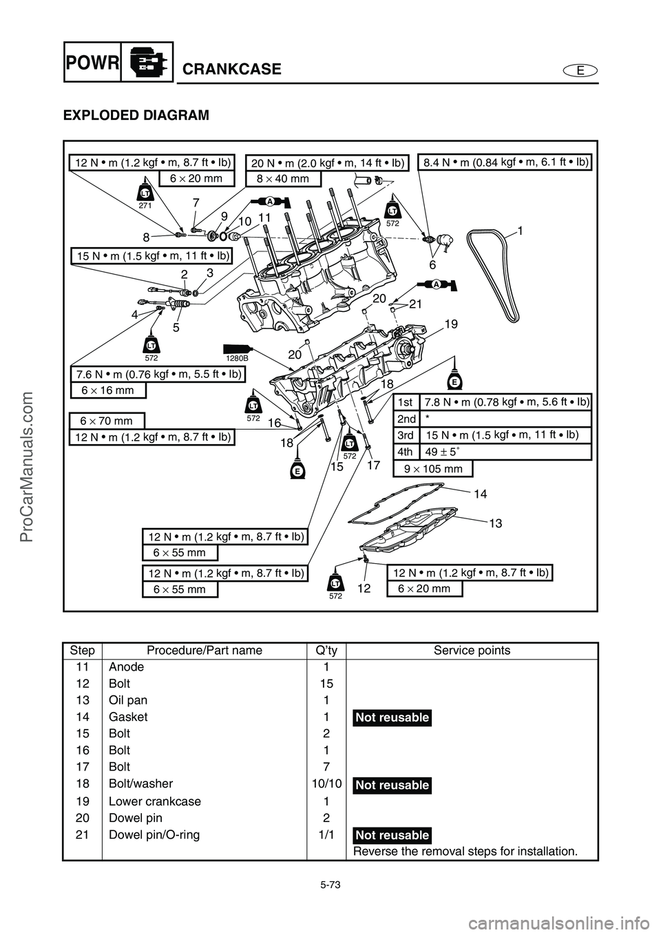
EXPLODED DIAGRAM
Step Procedure/Part name Q’ty Service points
Reduction drive gear case Refer to “REDUCTION DRIVE GEAR”.
Cylinder head Refer to “CAMSHAFTS”.
1 Timing chain 1
2 Engine temperature sensor 1
3 Washer 1
4Bolt 2
5 Thermoswitch (engine) 1
6 Oil pressure switch 1
7Bolt 1
8Bolt 1
9 Anode cover 1
10 Grommet 1
6
21 20
20 11
10 9
87
23
4
5
16
151718
13 14
1219
1
LT
271
LT
LT
572
LT
LT
572
LT
LT
572
LT
LT
572
LT
LT
572
LT
E
E
AA
12 N •
m (1.2 kgf • m, 8.7 ft • Ib)
6 × 70 mm
12 N •
m (1.2 kgf • m, 8.7 ft • Ib)
6 × 20 mm
20 N •
m (2.0 kgf • m, 14 ft • Ib)
8 × 40 mm
2nd *
3rd 15 N • m (1.5 kgf
• m, 11 ft
• Ib) 1st 7.8 N • m (0.78 kgf
• m, 5.6 ft
• Ib)
9 × 105 mm
4th 49 ± 5˚
8.4 N •
m (0.84 kgf • m, 6.1 ft • Ib)
12 N •
m (1.2 kgf • m, 8.7 ft • Ib)
6 × 55 mm
12 N •
m (1.2 kgf • m, 8.7 ft • Ib)
6 × 55 mm
7.6 N •
m (0.76 kgf • m, 5.5 ft • Ib)
6 × 16 mm
15 N •
m (1.5 kgf • m, 11 ft • Ib)
12 N •
m (1.2 kgf • m, 8.7 ft • Ib)
6 × 20 mm
18
AA
1280B
ProCarManuals.com
Page 172 of 347
5-73
EPOWRCRANKCASE
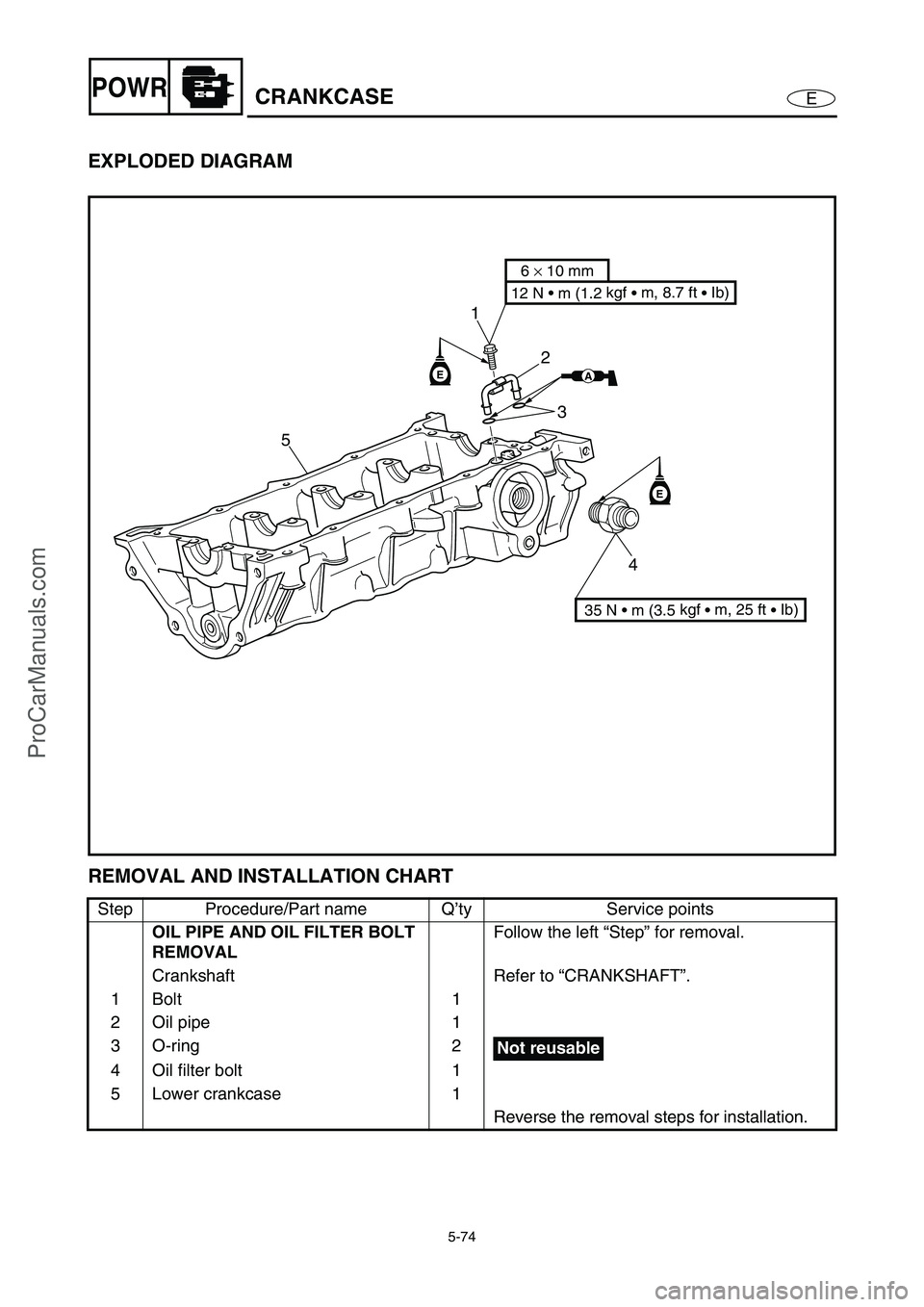
EXPLODED DIAGRAM
Step Procedure/Part name Q’ty Service points
11 Anode 1
12 Bolt 15
13 Oil pan 1
14 Gasket 1
15 Bolt 2
16 Bolt 1
17 Bolt 7
18 Bolt/washer 10/10
19 Lower crankcase 1
20 Dowel pin 2
21 Dowel pin/O-ring 1/1
Reverse the removal steps for installation.
6
21 20
20 11
10 9
87
23
4
5
16
151718
13 14
1219
1
LT
271
LT
LT
572
LT
LT
572
LT
LT
572
LT
LT
572
LT
LT
572
LT
E
E
AA
12 N •
m (1.2 kgf • m, 8.7 ft • Ib)
6 × 70 mm
12 N •
m (1.2 kgf • m, 8.7 ft • Ib)
6 × 20 mm
20 N •
m (2.0 kgf • m, 14 ft • Ib)
8 × 40 mm
2nd *
3rd 15 N • m (1.5 kgf
• m, 11 ft
• Ib) 1st 7.8 N • m (0.78 kgf
• m, 5.6 ft
• Ib)
9 × 105 mm
4th 49 ± 5˚
8.4 N •
m (0.84 kgf • m, 6.1 ft • Ib)
12 N •
m (1.2 kgf • m, 8.7 ft • Ib)
6 × 55 mm
12 N •
m (1.2 kgf • m, 8.7 ft • Ib)
6 × 55 mm
7.6 N •
m (0.76 kgf • m, 5.5 ft • Ib)
6 × 16 mm
15 N •
m (1.5 kgf • m, 11 ft • Ib)
12 N •
m (1.2 kgf • m, 8.7 ft • Ib)
6 × 20 mm
18
AA
1280B
Not reusable
Not reusable
Not reusable
ProCarManuals.com
Page 173 of 347
5-74
EPOWRCRANKCASE
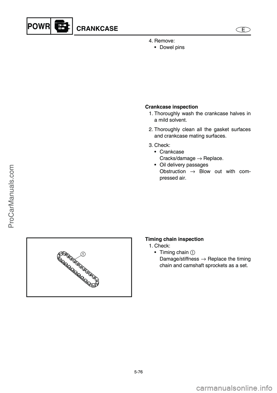
EXPLODED DIAGRAM
REMOVAL AND INSTALLATION CHART
Step Procedure/Part name Q’ty Service points
OIL PIPE AND OIL FILTER BOLT
REMOVALFollow the left “Step” for removal.
Crankshaft Refer to “CRANKSHAFT”.
1Bolt 1
2 Oil pipe 1
3 O-ring 2
4 Oil filter bolt 1
5 Lower crankcase 1
Reverse the removal steps for installation.
E
E
51
2
3
4
AA
6 × 10 mm
12 N • m (1.2 kgf
• m, 8.7 ft
• Ib)
35 N • m (3.5 kgf
• m, 25 ft
• Ib)
Not reusable
ProCarManuals.com
Page 174 of 347

5-75
EPOWRCRANKCASE
SERVICE POINTS
Crankcase disassembly
1. Remove:
Oil pan bolts
NOTE:
Loosen each bolt 1/4 of a turn at a time, in
stages and in a crisscross pattern. After all of
the bolts are fully loosened, remove them.
Loosen the bolts in decreasing numerical
order (refer to the numbers in the illustra-
tion).
The numbers embossed on the oil pan indi-
cate the oil pan tightening sequence.
106
24812
15
11
7
3 1 5 9
13 14
2. Remove:
Crankcase bolts
NOTE:
Loosen each bolt 1/4 of a turn at a time, in
stages and in a crisscross pattern. After all of
the bolts are fully loosened, remove them.
Loosen the bolts in decreasing numerical
order (refer to the numbers in the illustra-
tion).
The numbers embossed on the crankcase
indicate the crankcase tightening sequence.
3. Remove:
Lower crankcase
CAUTION:
Tap on one side of the crankcase with a
soft-face hammer. Tap only on reinforced
portions of the crankcase, not on the
crankcase mating surfaces. Work slowly
and carefully and make sure the crankcase
halves separate evenly.
M9
× 105 mm bolts:
1–
0
M6
× 55 mm bolts:
A–
H,
J
M6
× 70 mm bolts:
I
15397
ICAEG
86240
HFBDJ
ProCarManuals.com
Page 175 of 347
5-76
EPOWRCRANKCASE
4. Remove:
Dowel pins
Crankcase inspection
1. Thoroughly wash the crankcase halves in
a mild solvent.
2. Thoroughly clean all the gasket surfaces
and crankcase mating surfaces.
3. Check:
Crankcase
Cracks/damage →
Replace.
Oil delivery passages
Obstruction →
Blow out with com-
pressed air.
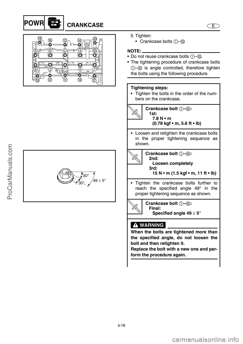
Timing chain inspection
1. Check:
Timing chain 1
Damage/stiffness →
Replace the timing
chain and camshaft sprockets as a set.
ProCarManuals.com
Page 176 of 347
5-77
EPOWRCRANKCASE
Crankcase assembly
1. Lubricate:
Crankshaft journal bearings
(with the recommended lubricant)
2. Apply:
ThreeBond 1280B
(onto the crankcase mating surfaces)
NOTE:
Do not allow any sealant to come into contact
with the oil gallery or crankshaft journal bear-
ings.
Recommended lubricant:
Engine oil
3. Install:
Dowel pins 1
O-ring 2
11
2
1
1280B
4. Install:
Crankcase bolts
NOTE:
Lubricate the bolt 1
–0 threads and wash-
ers with engine oil.
Finger tighten the crankcase bolts.
M9
× 105 mm bolts:
1–
0
M6
× 55 mm bolts:
A–
H,
J
M6
× 70 mm bolts:
I
15397
ICAEG
86240
HFBDJ
ProCarManuals.com
Page 177 of 347
5-78
EPOWRCRANKCASE
5. Tighten:
Crankcase bolts 1
–0
NOTE:
Do not reuse crankcase bolts 1
–0
.
The tightening procedure of crankcase bolts
1
–0
is angle controlled, therefore tighten
the bolts using the following procedure.
Tightening steps:
Tighten the bolts in the order of the num-
bers on the crankcase.
T R..
Crankcase bolt
1–
0:
1st:
7.8 N m
(0.78 kgf m, 5.6 ft lb)
Loosen and retighten the crankcase bolts
in the proper tightening sequence as
shown.
T R..
Crankcase bolt
1–
0:
2nd:
Loosen completely
3rd:
15 N m (1.5 kgf m, 11 ft lb)
Tighten the crankcase bolts further to
reach the specified angle 49° in the
proper tightening sequence as shown.
T R..
Crankcase bolt
1–
0:
Final:
Specified angle 49
± 5°
WARNING
When the bolts are tightened more than
the specified angle, do not loosen the
bolt and then retighten it.
Replace the bolt with a new one and per-
form the procedure again.
15397
ICAEG
86240
HFBDJ
ProCarManuals.com
Page 178 of 347
5-79
EPOWRCRANKCASE
CAUTION:
Do not use a torque wrench to tighten
the bolt to the specified angle.
Tighten the bolt until it is at the speci-
fied angle.
NOTE:
When using a hexagonal bolt, note that the
angle from one corner to another is 60°.
6. Tighten:
Crankcase bolts A
–J
NOTE:
Tighten the bolts in the order of the numbers
on the crankcase.
7. Tighten:
Oil pan bolts
NOTE:
Tighten the bolts in the order of the numbers
on the oil pan.
T R..
Crankcase bolt
A–
J:
12 N m (1.2 kgf m, 8.7 ft lb)
LOCTITE 572
T R..
Oil pan bolt:
12 N m (1.2 kgf m, 8.7 ft lb)
LOCTITE 572
15397
ICAEG
86240
HFBDJ
106
24812
15
11
7
3 1 5 9
13 14
ProCarManuals.com
Page 179 of 347
5-80
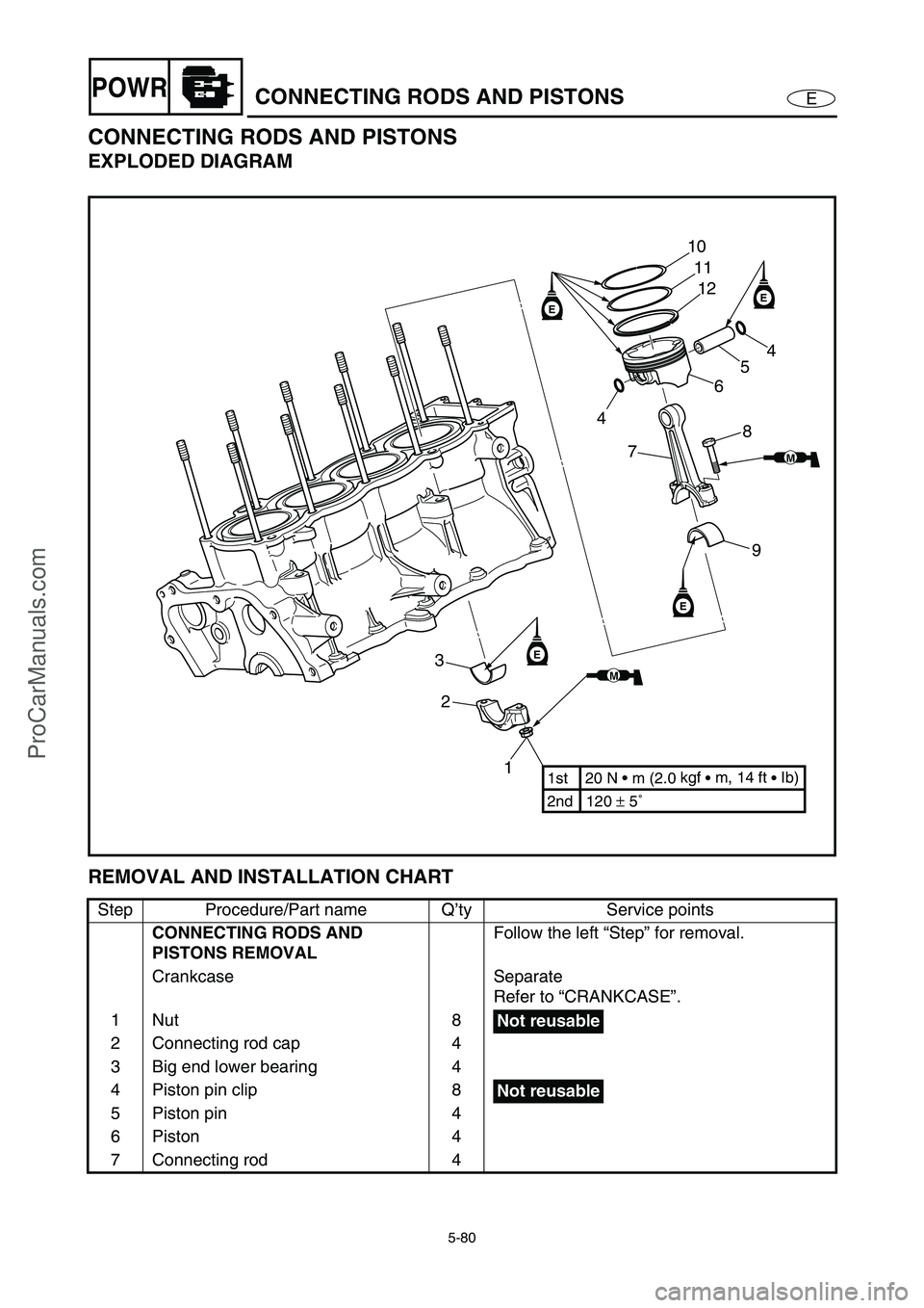
EPOWRCONNECTING RODS AND PISTONS
CONNECTING RODS AND PISTONS
EXPLODED DIAGRAM
REMOVAL AND INSTALLATION CHART
Step Procedure/Part name Q’ty Service points
CONNECTING RODS AND
PISTONS REMOVALFollow the left “Step” for removal.
Crankcase Separate
Refer to “CRANKCASE”.
1Nut 8
2 Connecting rod cap 4
3 Big end lower bearing 4
4 Piston pin clip 8
5 Piston pin 4
6Piston 4
7 Connecting rod 4
EE
E
E
1 2 310
11
12
4
5
6
8
7
9
2nd 120 ± 5˚ 1st 20 N • m (2.0 kgf
• m, 14 ft
• Ib)
MM
MM
4
Not reusable
Not reusable
ProCarManuals.com
Page 180 of 347
5-81
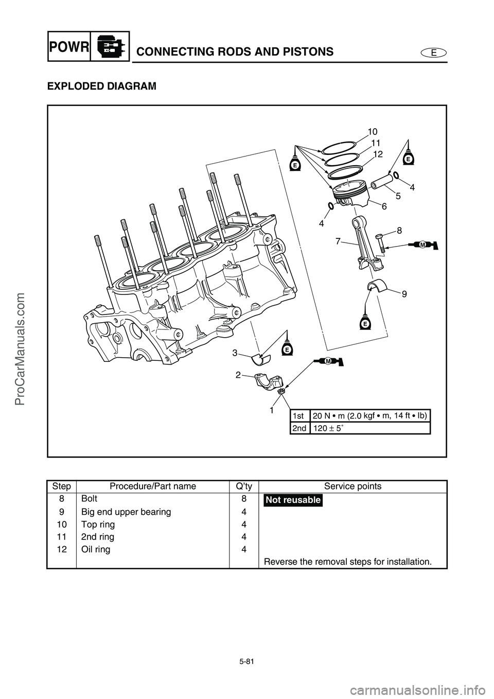
EPOWRCONNECTING RODS AND PISTONS
EXPLODED DIAGRAM
Step Procedure/Part name Q’ty Service points
8Bolt 8
9 Big end upper bearing 4
10 Top ring 4
11 2nd ring 4
12 Oil ring 4
Reverse the removal steps for installation.
EE
E
E
1 2 310
11
12
4
5
6
8
7
9
2nd 120 ± 5˚ 1st 20 N • m (2.0 kgf
• m, 14 ft
• Ib)
MM
MM
4
Not reusable
ProCarManuals.com
Trending: wheel bolt torque, wheel, oil temperature, remote control, seats, dimensions, octane

