YAMAHA WR 250F 2007 Notices Demploi (in French)
Manufacturer: YAMAHA, Model Year: 2007, Model line: WR 250F, Model: YAMAHA WR 250F 2007Pages: 912, PDF Size: 23.95 MB
Page 281 of 912
3 - 70
INSP
ADJ
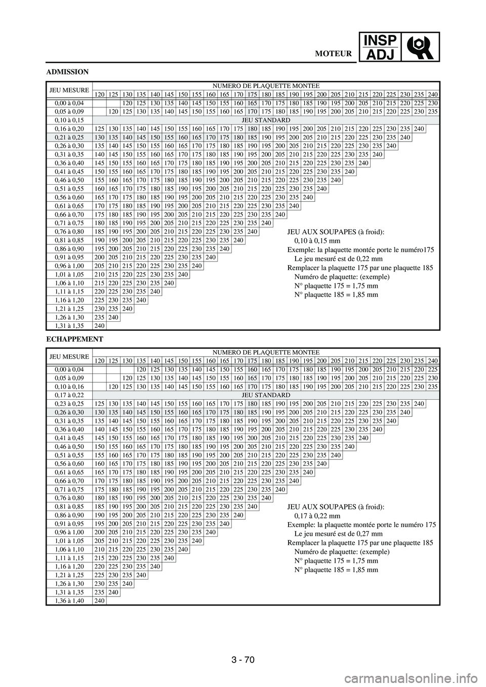
ADMISSION
ECHAPPEMENT
JEU MESURENUMERO DE PLAQUETTE MONTEE
120 125 130 135 140 145 150 155 160 165 170175 180 185 190 195 200 205 210 215 220 225 230 235 240
0,00 à 0,04 120 125 130 135 140 145 150 155
160165 170 175 180 185 190 195 200 205 210 215 220 225 230
0,05 à 0,09
120 125 130 135 140 145 150 155 160 165170 175 180 185 190 195 200 205 210 215 220 225 230 235
0,10 à 0,15
JEU STANDARD
0,16 à 0,20125130135140145150155160165170175180 185 190 195 200 205 210 215 220 225 230 235240
0,21 à 0,25130135140145150155160165170175180185 190 195 200 205 210 215 220 225 230 235240
0,26 à 0,30 135 140 145 150 155 160 165 170 175 180 185 190 195 200 205 210 215 220 225 230 235240
0,31 à 0,35 140 145 150 155 160 165 170 175 180 185 190 195 200 205 210 215 220 225 230 235240
0,36 à 0,40 145 150 155 160 165 170 175 180 185 190 195 200 205 210 215 220 225 230 235240
0,41 à 0,45 150 155 160 165 170 175 180 185 190 195 200 205 210 215 220 225 230 235240
0,46 à 0,50 155 160 165 170 175 180 185 190 195 200 205 210 215 220 225 230 235240
0,51 à 0,55 160 165 170 175 180 185 190 195 200 205 210 215 220 225 230 235240
0,56 à 0,60 165 170 175 180 185 190 195 200 205 210 215 220 225 230 235240
0,61 à 0,65 170 175 180 185 190 195 200 205 210 215 220 225 230 235240
0,66 à 0,70 175 180 185 190 195 200 205 210 215 220 225 230 235240
0,71 à 0,75 180 185 190 195 200 205 210 215 220 225 230 235240
0,76 à 0,80 185 190 195 200 205 210 215 220 225 230 235240JEU AUX SOUPAPES (à froid):
0,10 à 0,15 mm
Exemple: la plaquette montée porte le numéro175
Le jeu mesuré est de 0,22 mm
Remplacer la plaquette 175 par une plaquette 185
Numéro de plaquette: (exemple)
N° plaquette 175 = 1,75 mm
N° plaquette 185 = 1,85 mm0,81 à 0,85 190 195 200 205 210 215 220 225 230 235240
0,86 à 0,90 195 200 205 210 215 220 225 230 235240
0,91 à 0,95 200 205 210 215 220 225 230 235240
0,96 à 1,00 205 210 215 220 225 230 235240
1,01 à 1,05 210 215 220 225 230 235240
1,06 à 1,10 215 220 225 230 235240
1,11 à 1,15 220 225 230 235240
1,16 à 1,20 225 230 235240
1,21 à 1,25 230 235240
1,26 à 1,30 235240
1,31 à 1,35 240
JEU MESURENUMERO DE PLAQUETTE MONTEE
120 125 130 135 140 145 150 155 160 165 170175 180 185 190 195 200 205 210 215 220 225 230 235 240
0,00 à 0,04 120 125 130 135 140 145 150 155
160 165 170 175 180 185 190 195 200 205 210 215 220 225
0,05 à 0,09
120 125 130 135 140 145 150 155 160165 170 175 180 185 190 195 200 205 210 215 220 225 230
0,10 à 0,16
120125130135140145150155160165170 175 180 185 190 195 200 205 210 215 220 225230235
0,17 à 0,22JEU STANDARD
0,23 à 0,25 125 130 135 140 145 150 155 160 165 170 175
180 185 190 195 200 205 210 215 220 225230235240
0,26 à 0,30130135140145150155160165170175180185 190 195 200 205 210 215 220 225230235240
0,31 à 0,35 135 140 145 150 155 160 165 170 175 180 185 190 195 200 205 210 215 220 225230235240
0,36 à 0,40 140 145 150 155 160 165 170 175 180 185 190 195 200 205 210 215 220 225230235240
0,41 à 0,45 145 150 155 160 165 170 175 180 185 190 195 200 205 210 215 220 225230235240
0,46 à 0,50 150 155 160 165 170 175 180 185 190 195 200 205 210 215 220 225230235240
0,51 à 0,55 155 160 165 170 175 180 185 190 195 200 205 210 215 220 225230235240
0,56 à 0,60 160 165 170 175 180 185 190 195 200 205 210 215 220 225230235240
0,61 à 0,65 165 170 175 180 185 190 195 200 205 210 215 220 225230235240
0,66 à 0,70 170 175 180 185 190 195 200 205 210 215 220 225230235240
0,71 à 0,75 175 180 185 190 195 200 205 210 215 220 225230235240
0,76 à 0,80 180 185 190 195 200 205 210 215 220 225230235240
0,81 à 0,85 185 190 195 200 205 210 215 220 225230235240JEU AUX SOUPAPES (à froid):
0,17 à 0,22 mm
Exemple: la plaquette montée porte le numéro 175
Le jeu mesuré est de 0,27 mm
Remplacer la plaquette 175 par une plaquette 185
Numéro de plaquette: (exemple)
N° plaquette 175 = 1,75 mm
N° plaquette 185 = 1,85 mm0,86 à 0,90 190 195 200 205 210 215 220 225230235240
0,91 à 0,95 195 200 205 210 215 220 225230235240
0,96 à 1,00 200 205 210 215 220 225230235240
1,01 à 1,05 205 210 215 220 225230235240
1,06 à 1,10 210 215 220 225230235240
1,11 à 1,15 215 220 225230235240
1,16 à 1,20 220 225230235240
1,21 à 1,25 225230235240
1,26 à 1,30 230235240
1,31 à 1,35 235240
1,36 à 1,40 240
MOTEUR
Page 282 of 912
3 - 71
INSP
ADJ
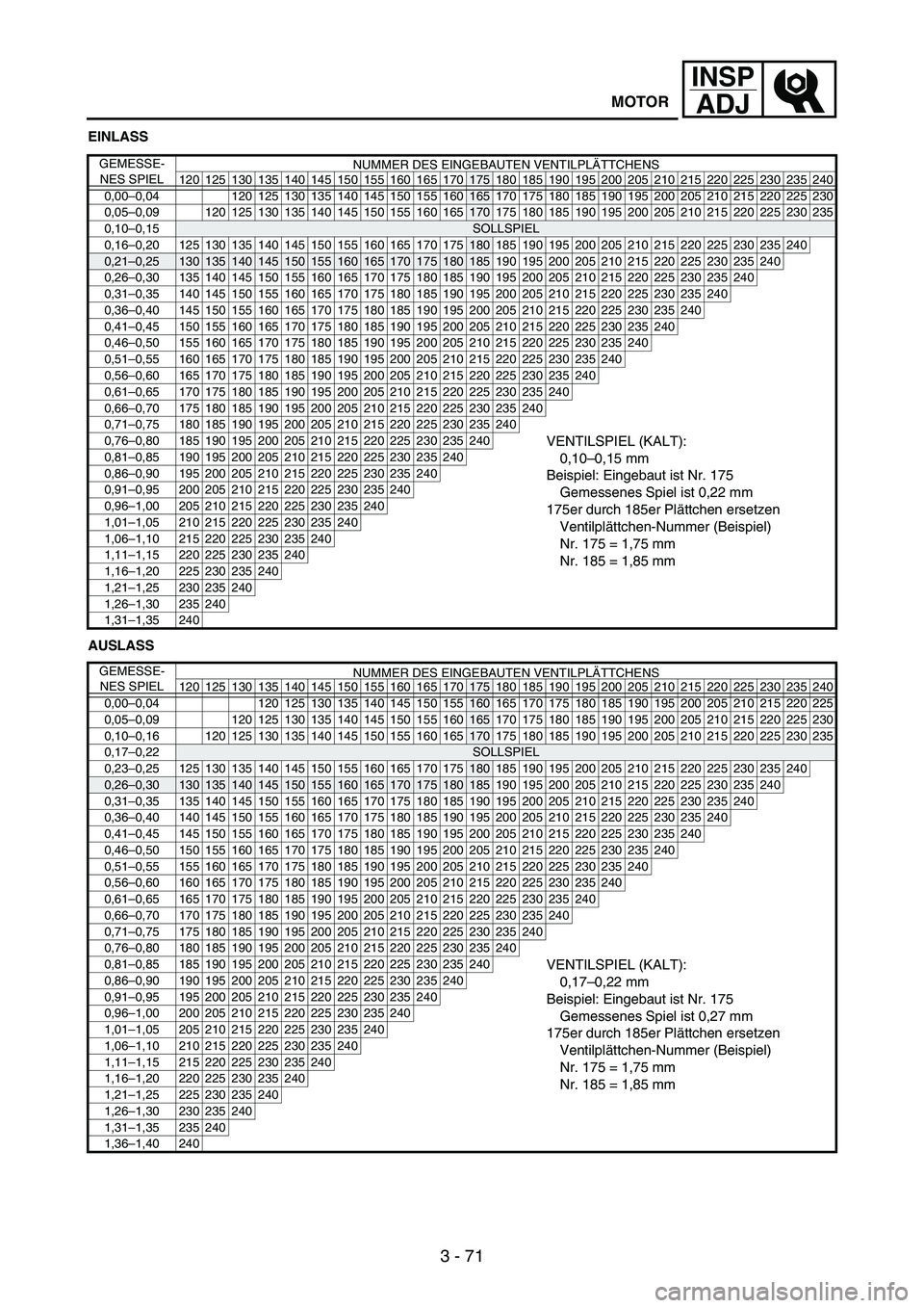
EINLASS
AUSLASS
GEMESSE-
NES SPIELNUMMER DES EINGEBAUTEN VENTILPLÄTTCHENS
120 125 130 135 140 145 150 155 160 165 170
175 180 185 190 195 200 205 210 215 220 225 230 235 240
0,00–0,04 120 125 130 135 140 145 150 155
160165 170 175 180 185 190 195 200 205 210 215 220 225 230
0,05–0,09
120 125 130 135 140 145 150 155 160 165170 175 180 185 190 195 200 205 210 215 220 225 230 235
0,10–0,15
SOLLSPIEL
0,16–0,20125130135140145150155160165170175180 185 190 195 200 205 210 215 220 225 230 235240
0,21–0,25130135140145150155160165170175180185 190 195 200 205 210 215 220 225 230 235240
0,26–0,30 135 140 145 150 155 160 165 170 175 180 185 190 195 200 205 210 215 220 225 230 235240
0,31–0,35 140 145 150 155 160 165 170 175 180 185 190 195 200 205 210 215 220 225 230 235240
0,36–0,40 145 150 155 160 165 170 175 180 185 190 195 200 205 210 215 220 225 230 235240
0,41–0,45 150 155 160 165 170 175 180 185 190 195 200 205 210 215 220 225 230 235240
0,46–0,50 155 160 165 170 175 180 185 190 195 200 205 210 215 220 225 230 235240
0,51–0,55 160 165 170 175 180 185 190 195 200 205 210 215 220 225 230 235240
0,56–0,60 165 170 175 180 185 190 195 200 205 210 215 220 225 230 235240
0,61–0,65 170 175 180 185 190 195 200 205 210 215 220 225 230 235240
0,66–0,70 175 180 185 190 195 200 205 210 215 220 225 230 235240
0,71–0,75 180 185 190 195 200 205 210 215 220 225 230 235240
0,76–0,80 185 190 195 200 205 210 215 220 225 230 235240VENTILSPIEL (KALT):
0,10–0,15 mm
Beispiel: Eingebaut ist Nr. 175
Gemessenes Spiel ist 0,22 mm
175er durch 185er Plättchen ersetzen
Ventilplättchen-Nummer (Beispiel)
Nr. 175 = 1,75 mm
Nr. 185 = 1,85 mm0,81–0,85 190 195 200 205 210 215 220 225 230 235240
0,86–0,90 195 200 205 210 215 220 225 230 235240
0,91–0,95 200 205 210 215 220 225 230 235240
0,96–1,00 205 210 215 220 225 230 235240
1,01–1,05 210 215 220 225 230 235240
1,06–1,10 215 220 225 230 235240
1,11–1,15 220 225 230 235240
1,16–1,20 225 230 235240
1,21–1,25 230 235240
1,26–1,30 235240
1,31–1,35 240
GEMESSE-
NES SPIELNUMMER DES EINGEBAUTEN VENTILPLÄTTCHENS
120 125 130 135 140 145 150 155 160 165 170
175 180 185 190 195 200 205 210 215 220 225 230 235 240
0,00–0,04 120 125 130 135 140 145 150 155
160 165 170 175 180 185 190 195 200 205 210 215 220 225
0,05–0,09
120 125 130 135 140 145 150 155 160165 170 175 180 185 190 195 200 205 210 215 220 225 230
0,10–0,16
120125130135140145150155160165170 175 180 185 190 195 200 205 210 215 220 225230235
0,17–0,22SOLLSPIEL
0,23–0,25 125 130 135 140 145 150 155 160 165 170 175
180 185 190 195 200 205 210 215 220 225230235240
0,26–0,30130135140145150155160165170175180185 190 195 200 205 210 215 220 225230235240
0,31–0,35 135 140 145 150 155 160 165 170 175 180 185 190 195 200 205 210 215 220 225230235240
0,36–0,40 140 145 150 155 160 165 170 175 180 185 190 195 200 205 210 215 220 225230235240
0,41–0,45 145 150 155 160 165 170 175 180 185 190 195 200 205 210 215 220 225230235240
0,46–0,50 150 155 160 165 170 175 180 185 190 195 200 205 210 215 220 225230235240
0,51–0,55 155 160 165 170 175 180 185 190 195 200 205 210 215 220 225230235240
0,56–0,60 160 165 170 175 180 185 190 195 200 205 210 215 220 225230235240
0,61–0,65 165 170 175 180 185 190 195 200 205 210 215 220 225230235240
0,66–0,70 170 175 180 185 190 195 200 205 210 215 220 225230235240
0,71–0,75 175 180 185 190 195 200 205 210 215 220 225230235240
0,76–0,80 180 185 190 195 200 205 210 215 220 225230235240
0,81–0,85 185 190 195 200 205 210 215 220 225230235240VENTILSPIEL (KALT):
0,17–0,22 mm
Beispiel: Eingebaut ist Nr. 175
Gemessenes Spiel ist 0,27 mm
175er durch 185er Plättchen ersetzen
Ventilplättchen-Nummer (Beispiel)
Nr. 175 = 1,75 mm
Nr. 185 = 1,85 mm0,86–0,90 190 195 200 205 210 215 220 225230235240
0,91–0,95 195 200 205 210 215 220 225230235240
0,96–1,00 200 205 210 215 220 225230235240
1,01–1,05 205 210 215 220 225230235240
1,06–1,10 210 215 220 225230235240
1,11–1,15 215 220 225230235240
1,16–1,20 220 225230235240
1,21–1,25 225230235240
1,26–1,30 230235240
1,31–1,35 235240
1,36–1,40 240
MOTOR
Page 283 of 912
3 - 72
INSP
ADJ
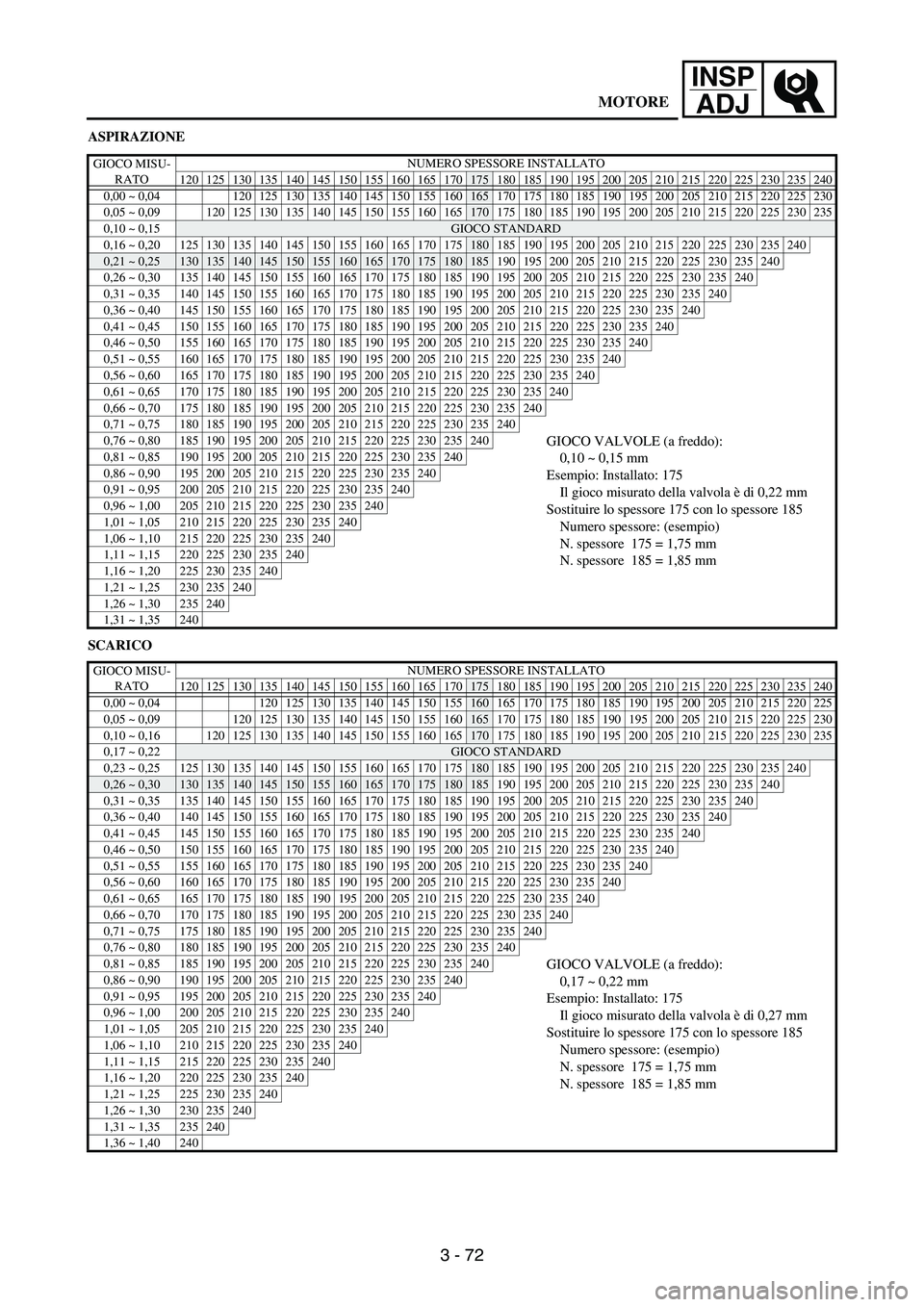
ASPIRAZIONE
SCARICO
GIOCO MISU-
RATONUMERO SPESSORE INSTALLATO
120 125 130 135 140 145 150 155 160 165 170
175 180 185 190 195 200 205 210 215 220 225 230 235 240
0,00 ~ 0,04 120 125 130 135 140 145 150 155
160165 170 175 180 185 190 195 200 205 210 215 220 225 230
0,05 ~ 0,09
120 125 130 135 140 145 150 155 160 165170 175 180 185 190 195 200 205 210 215 220 225 230 235
0,10 ~ 0,15
GIOCO STANDARD
0,16 ~ 0,20125130135140145150155160165170175180 185 190 195 200 205 210 215 220 225 230 235240
0,21 ~ 0,25130135140145150155160165170175180185 190 195 200 205 210 215 220 225 230 235240
0,26 ~ 0,30 135 140 145 150 155 160 165 170 175 180 185 190 195 200 205 210 215 220 225 230 235240
0,31 ~ 0,35 140 145 150 155 160 165 170 175 180 185 190 195 200 205 210 215 220 225 230 235240
0,36 ~ 0,40 145 150 155 160 165 170 175 180 185 190 195 200 205 210 215 220 225 230 235240
0,41 ~ 0,45 150 155 160 165 170 175 180 185 190 195 200 205 210 215 220 225 230 235240
0,46 ~ 0,50 155 160 165 170 175 180 185 190 195 200 205 210 215 220 225 230 235240
0,51 ~ 0,55 160 165 170 175 180 185 190 195 200 205 210 215 220 225 230 235240
0,56 ~ 0,60 165 170 175 180 185 190 195 200 205 210 215 220 225 230 235240
0,61 ~ 0,65 170 175 180 185 190 195 200 205 210 215 220 225 230 235240
0,66 ~ 0,70 175 180 185 190 195 200 205 210 215 220 225 230 235240
0,71 ~ 0,75 180 185 190 195 200 205 210 215 220 225 230 235240
0,76 ~ 0,80 185 190 195 200 205 210 215 220 225 230 235240GIOCO VALVOLE (a freddo):
0,10 ~ 0,15 mm
Esempio: Installato: 175
Il gioco misurato della valvola è di 0,22 mm
Sostituire lo spessore 175 con lo spessore 185
Numero spessore: (esempio)
N. spessore 175 = 1,75 mm
N. spessore 185 = 1,85 mm0,81 ~ 0,85 190 195 200 205 210 215 220 225 230 235240
0,86 ~ 0,90 195 200 205 210 215 220 225 230 235240
0,91 ~ 0,95 200 205 210 215 220 225 230 235240
0,96 ~ 1,00 205 210 215 220 225 230 235240
1,01 ~ 1,05 210 215 220 225 230 235240
1,06 ~ 1,10 215 220 225 230 235240
1,11 ~ 1,15 220 225 230 235240
1,16 ~ 1,20 225 230 235240
1,21 ~ 1,25 230 235240
1,26 ~ 1,30 235240
1,31 ~ 1,35 240
GIOCO MISU-
RATONUMERO SPESSORE INSTALLATO
120 125 130 135 140 145 150 155 160 165 170
175 180 185 190 195 200 205 210 215 220 225 230 235 240
0,00 ~ 0,04 120 125 130 135 140 145 150 155
160 165 170 175 180 185 190 195 200 205 210 215 220 225
0,05 ~ 0,09
120 125 130 135 140 145 150 155 160165 170 175 180 185 190 195 200 205 210 215 220 225 230
0,10 ~ 0,16
120125130135140145150155160165170 175 180 185 190 195 200 205 210 215 220 225230235
0,17 ~ 0,22GIOCO STANDARD
0,23 ~ 0,25 125 130 135 140 145 150 155 160 165 170 175
180 185 190 195 200 205 210 215 220 225230235240
0,26 ~ 0,30130135140145150155160165170175180185 190 195 200 205 210 215 220 225230235240
0,31 ~ 0,35 135 140 145 150 155 160 165 170 175 180 185 190 195 200 205 210 215 220 225230235240
0,36 ~ 0,40 140 145 150 155 160 165 170 175 180 185 190 195 200 205 210 215 220 225230235240
0,41 ~ 0,45 145 150 155 160 165 170 175 180 185 190 195 200 205 210 215 220 225230235240
0,46 ~ 0,50 150 155 160 165 170 175 180 185 190 195 200 205 210 215 220 225230235240
0,51 ~ 0,55 155 160 165 170 175 180 185 190 195 200 205 210 215 220 225230235240
0,56 ~ 0,60 160 165 170 175 180 185 190 195 200 205 210 215 220 225230235240
0,61 ~ 0,65 165 170 175 180 185 190 195 200 205 210 215 220 225230235240
0,66 ~ 0,70 170 175 180 185 190 195 200 205 210 215 220 225230235240
0,71 ~ 0,75 175 180 185 190 195 200 205 210 215 220 225230235240
0,76 ~ 0,80 180 185 190 195 200 205 210 215 220 225230235240
0,81 ~ 0,85 185 190 195 200 205 210 215 220 225230235240GIOCO VALVOLE (a freddo):
0,17 ~ 0,22 mm
Esempio: Installato: 175
Il gioco misurato della valvola è di 0,27 mm
Sostituire lo spessore 175 con lo spessore 185
Numero spessore: (esempio)
N. spessore 175 = 1,75 mm
N. spessore 185 = 1,85 mm0,86 ~ 0,90 190 195 200 205 210 215 220 225230235240
0,91 ~ 0,95 195 200 205 210 215 220 225230235240
0,96 ~ 1,00 200 205 210 215 220 225230235240
1,01 ~ 1,05 205 210 215 220 225230235240
1,06 ~ 1,10 210 215 220 225230235240
1,11 ~ 1,15 215 220 225230235240
1,16 ~ 1,20 220 225230235240
1,21 ~ 1,25 225230235240
1,26 ~ 1,30 230235240
1,31 ~ 1,35 235240
1,36 ~ 1,40 240
MOTORE
Page 284 of 912
3 - 73
INSP
ADJ
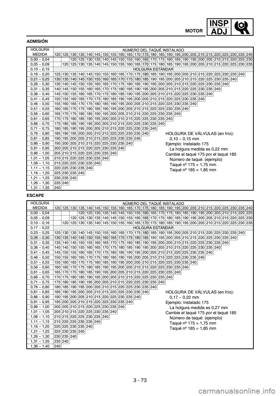
ADMISIÓN
ESCAPE
HOLGURA
MEDIDANÚMERO DEL TAQUÉ INSTALADO
120 125 130 135 140 145 150 155 160 165 170
175 180 185 190 195 200 205 210 215 220 225 230 235 240
0,00 ~ 0,04 120 125 130 135 140 145 150 155
160165 170 175 180 185 190 195 200 205 210 215 220 225 230
0,05 ~ 0,09
120 125 130 135 140 145 150 155 160 165170 175 180 185 190 195 200 205 210 215 220 225 230 235
0,10 ~ 0,15
HOLGURA ESTÁNDAR
0,16 ~ 0,20125130135140145150155160165170175180 185 190 195 200 205 210 215 220 225 230 235240
0,21 ~ 0,25130135140145150155160165170175180185 190 195 200 205 210 215 220 225 230 235240
0,26 ~ 0,30 135 140 145 150 155 160 165 170 175 180 185 190 195 200 205 210 215 220 225 230 235240
0,31 ~ 0,35 140 145 150 155 160 165 170 175 180 185 190 195 200 205 210 215 220 225 230 235240
0,36 ~ 0,40 145 150 155 160 165 170 175 180 185 190 195 200 205 210 215 220 225 230 235240
0,41 ~ 0,45 150 155 160 165 170 175 180 185 190 195 200 205 210 215 220 225 230 235240
0,46 ~ 0,50 155 160 165 170 175 180 185 190 195 200 205 210 215 220 225 230 235240
0,51 ~ 0,55 160 165 170 175 180 185 190 195 200 205 210 215 220 225 230 235240
0,56 ~ 0,60 165 170 175 180 185 190 195 200 205 210 215 220 225 230 235240
0,61 ~ 0,65 170 175 180 185 190 195 200 205 210 215 220 225 230 235240
0,66 ~ 0,70 175 180 185 190 195 200 205 210 215 220 225 230 235240
0,71 ~ 0,75 180 185 190 195 200 205 210 215 220 225 230 235240
0,76 ~ 0,80 185 190 195 200 205 210 215 220 225 230 235240HOLGURA DE VÁLVULAS (en frío):
0,10 ~ 0,15 mm
Ejemplo: Instalado 175
La holgura medida es 0,22 mm
Cambie el taqué 175 por el taqué 185
Número de taqué: (ejemplo)
Taqué nº175 = 1,75 mm
Taqué nº185 = 1,85 mm0,81 ~ 0,85 190 195 200 205 210 215 220 225 230 235240
0,86 ~ 0,90 195 200 205 210 215 220 225 230 235240
0,91 ~ 0,95 200 205 210 215 220 225 230 235240
0,96 ~ 1,00 205 210 215 220 225 230 235240
1,01 ~ 1,05 210 215 220 225 230 235240
1,06 ~ 1,10 215 220 225 230 235240
1,11 ~ 1,15 220 225 230 235240
1,16 ~ 1,20 225 230 235240
1,21 ~ 1,25 230 235240
1,26 ~ 1,30 235240
1,31 ~ 1,35 240
HOLGURA
MEDIDANÚMERO DEL TAQUÉ INSTALADO
120 125 130 135 140 145 150 155 160 165 170
175 180 185 190 195 200 205 210 215 220 225 230 235 240
0,00 ~ 0,04 120 125 130 135 140 145 150 155
160 165 170 175 180 185 190 195 200 205 210 215 220 225
0,05 ~ 0,09
120 125 130 135 140 145 150 155 160165 170 175 180 185 190 195 200 205 210 215 220 225 230
0,10 ~ 0,16
120125130135140145150155160165170 175 180 185 190 195 200 205 210 215 220 225230235
0,17 ~ 0,22HOLGURA ESTÁNDAR
0,23 ~ 0,25 125 130 135 140 145 150 155 160 165 170 175
180 185 190 195 200 205 210 215 220 225230235240
0,26 ~ 0,30130135140145150155160165170175180185 190 195 200 205 210 215 220 225230235240
0,31 ~ 0,35 135 140 145 150 155 160 165 170 175 180 185 190 195 200 205 210 215 220 225230235240
0,36 ~ 0,40 140 145 150 155 160 165 170 175 180 185 190 195 200 205 210 215 220 225230235240
0,41 ~ 0,45 145 150 155 160 165 170 175 180 185 190 195 200 205 210 215 220 225230235240
0,46 ~ 0,50 150 155 160 165 170 175 180 185 190 195 200 205 210 215 220 225230235240
0,51 ~ 0,55 155 160 165 170 175 180 185 190 195 200 205 210 215 220 225230235240
0,56 ~ 0,60 160 165 170 175 180 185 190 195 200 205 210 215 220 225230235240
0,61 ~ 0,65 165 170 175 180 185 190 195 200 205 210 215 220 225230235240
0,66 ~ 0,70 170 175 180 185 190 195 200 205 210 215 220 225230235240
0,71 ~ 0,75 175 180 185 190 195 200 205 210 215 220 225230235240
0,76 ~ 0,80 180 185 190 195 200 205 210 215 220 225230235240
0,81 ~ 0,85 185 190 195 200 205 210 215 220 225230235240HOLGURA DE VÁLVULAS (en frío):
0,17 ~ 0,22 mm
Ejemplo: Instalado 175
La holgura medida es 0,27 mm
Cambie el taqué 175 por el taqué 185
Número de taqué: (ejemplo)
Taqué nº175 = 1,75 mm
Taqué nº185 = 1,85 mm0,86 ~ 0,90 190 195 200 205 210 215 220 225230235240
0,91 ~ 0,95 195 200 205 210 215 220 225230235240
0,96 ~ 1,00 200 205 210 215 220 225230235240
1,01 ~ 1,05 205 210 215 220 225230235240
1,06 ~ 1,10 210 215 220 225230235240
1,11 ~ 1,15 215 220 225230235240
1,16 ~ 1,20 220 225230235240
1,21 ~ 1,25 225230235240
1,26 ~ 1,30 230235240
1,31 ~ 1,35 235240
1,36 ~ 1,40 240
MOTOR
Page 285 of 912
3 - 74
INSP
ADJ
MEMO
Page 286 of 912
3 - 75
INSP
ADJ
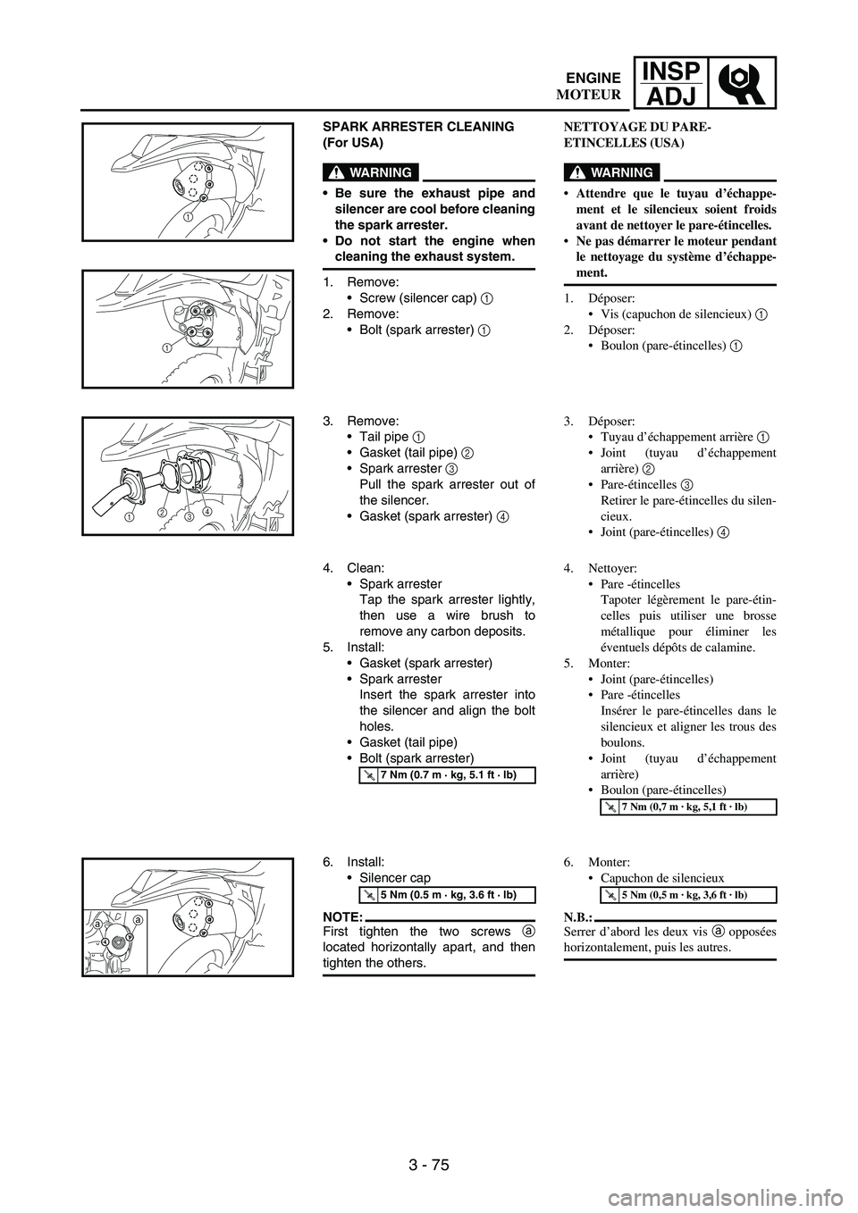
SPARK ARRESTER CLEANING
(For USA)
WARNING
Be sure the exhaust pipe and
silencer are cool before cleaning
the spark arrester.
Do not start the engine when
cleaning the exhaust system.
1. Remove:
Screw (silencer cap)
1
2. Remove:
Bolt (spark arrester)
1
1
1
3. Remove:
Tail pipe
1
Gasket (tail pipe)
2
Spark arrester 3
Pull the spark arrester out of
the silencer.
Gasket (spark arrester) 4
12
34
4. Clean:
Spark arrester
Tap the spark arrester lightly,
then use a wire brush to
remove any carbon deposits.
5. Install:
Gasket (spark arrester)
Spark arrester
Insert the spark arrester into
the silencer and align the bolt
holes.
Gasket (tail pipe)
Bolt (spark arrester)
T R..7 Nm (0.7 m · kg, 5.1 ft · lb)
6. Install:
Silencer cap
NOTE:First tighten the two screws a
located horizontally apart, and then
tighten the others.
T R..5 Nm (0.5 m · kg, 3.6 ft · lb)
aa
NETTOYAGE DU PARE-
ETINCELLES (USA)
WARNING
Attendre que le tuyau d’échappe-
ment et le silencieux soient froids
avant de nettoyer le pare-étincelles.
Ne pas démarrer le moteur pendant
le nettoyage du système d’échappe-
ment.
1. Déposer:
Vis (capuchon de silencieux) 1
2. Déposer:
Boulon (pare-étincelles) 1
3. Déposer:
Tuyau d’échappement arrière 1
Joint (tuyau d’échappement
arrière) 2
Pare-étincelles 3
Retirer le pare-étincelles du silen-
cieux.
Joint (pare-étincelles) 4
4. Nettoyer:
Pare -étincelles
Tapoter légèrement le pare-étin-
celles puis utiliser une brosse
métallique pour éliminer les
éventuels dépôts de calamine.
5. Monter:
Joint (pare-étincelles)
Pare -étincelles
Insérer le pare-étincelles dans le
silencieux et aligner les trous des
boulons.
Joint (tuyau d’échappement
arrière)
Boulon (pare-étincelles)
T R..7 Nm (0,7 m · kg, 5,1 ft · lb)
6. Monter:
Capuchon de silencieux
N.B.:
Serrer d’abord les deux vis a opposées
horizontalement, puis les autres.
T R..5 Nm (0,5 m · kg, 3,6 ft · lb)
ENGINE
MOTEUR
Page 287 of 912
INSP
ADJ
3 - 76
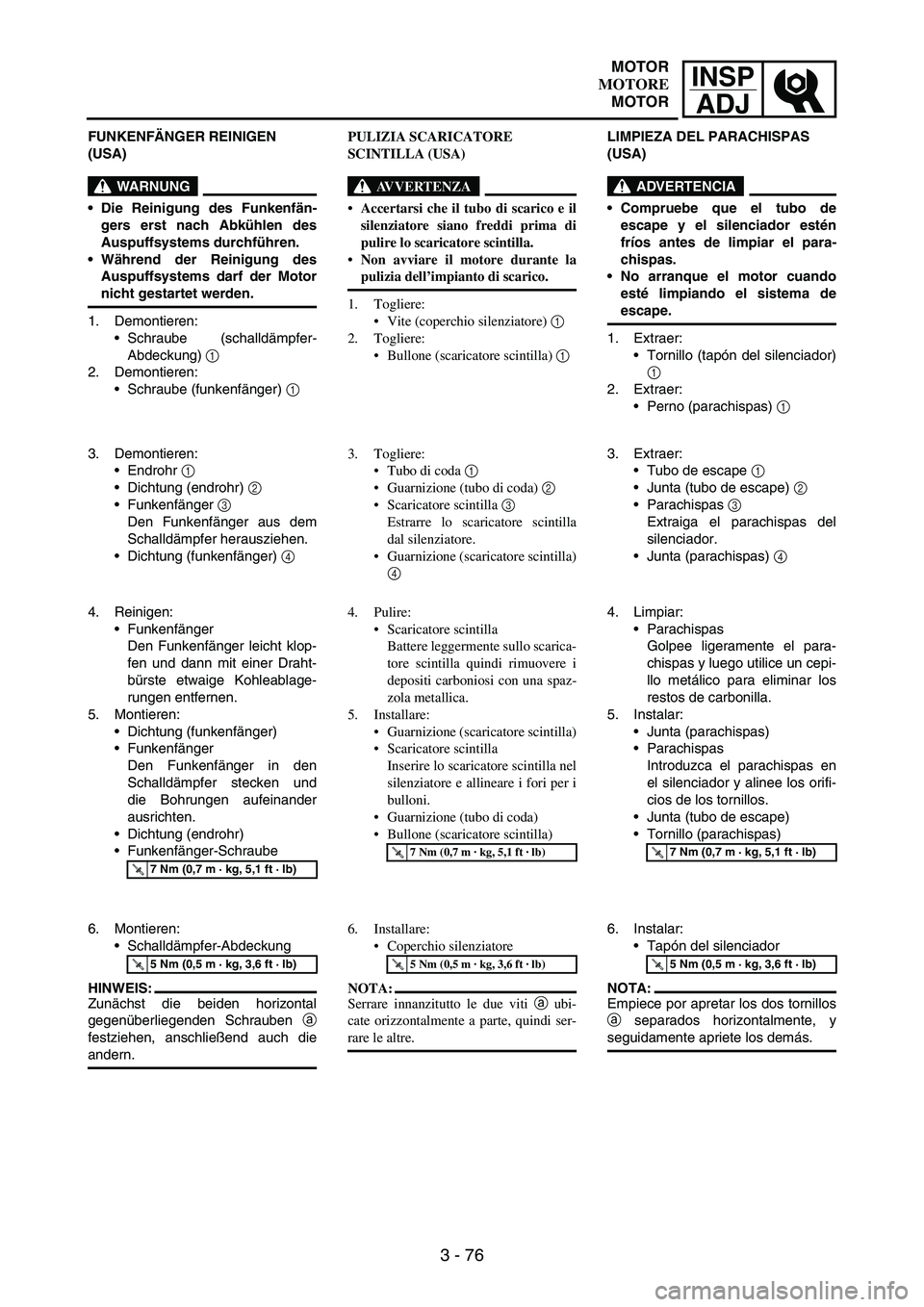
FUNKENFÄNGER REINIGEN
(USA)
WARNUNG
Die Reinigung des Funkenfän-
gers erst nach Abkühlen des
Auspuffsystems durchführen.
Während der Reinigung des
Auspuffsystems darf der Motor
nicht gestartet werden.
1. Demontieren:
Schraube (schalldämpfer-
Abdeckung)
1
2. Demontieren:
Schraube (funkenfänger)
1
3. Demontieren:
Endrohr
1
Dichtung (endrohr)
2
Funkenfänger
3
Den Funkenfänger aus dem
Schalldämpfer herausziehen.
Dichtung (funkenfänger)
4
4. Reinigen:
Funkenfänger
Den Funkenfänger leicht klop-
fen und dann mit einer Draht-
bürste etwaige Kohleablage-
rungen entfernen.
5. Montieren:
Dichtung (funkenfänger)
Funkenfänger
Den Funkenfänger in den
Schalldämpfer stecken und
die Bohrungen aufeinander
ausrichten.
Dichtung (endrohr)
Funkenfänger-Schraube
T R..7 Nm (0,7 m · kg, 5,1 ft · lb)
6. Montieren:
Schalldämpfer-Abdeckung
HINWEIS:
Zunächst die beiden horizontal
gegenüberliegenden Schrauben
a
festziehen, anschließend auch die
andern.
T R..5 Nm (0,5 m · kg, 3,6 ft · lb)
PULIZIA SCARICATORE
SCINTILLA (USA)
AVVERTENZA
Accertarsi che il tubo di scarico e il
silenziatore siano freddi prima di
pulire lo scaricatore scintilla.
Non avviare il motore durante la
pulizia dell’impianto di scarico.
1. Togliere:
Vite (coperchio silenziatore) 1
2. Togliere:
Bullone (scaricatore scintilla) 1
3. Togliere:
Tubo di coda 1
Guarnizione (tubo di coda) 2
Scaricatore scintilla 3
Estrarre lo scaricatore scintilla
dal silenziatore.
Guarnizione (scaricatore scintilla)
4
4. Pulire:
Scaricatore scintilla
Battere leggermente sullo scarica-
tore scintilla quindi rimuovere i
depositi carboniosi con una spaz-
zola metallica.
5. Installare:
Guarnizione (scaricatore scintilla)
Scaricatore scintilla
Inserire lo scaricatore scintilla nel
silenziatore e allineare i fori per i
bulloni.
Guarnizione (tubo di coda)
Bullone (scaricatore scintilla)
T R..7 Nm (0,7 m · kg, 5,1 ft · lb)
6. Installare:
Coperchio silenziatore
NOTA:
Serrare innanzitutto le due viti a ubi-
cate orizzontalmente a parte, quindi ser-
rare le altre.
T R..5 Nm (0,5 m · kg, 3,6 ft · lb)
LIMPIEZA DEL PARACHISPAS
(USA)
ADVERTENCIA
Compruebe que el tubo de
escape y el silenciador estén
fríos antes de limpiar el para-
chispas.
No arranque el motor cuando
esté limpiando el sistema de
escape.
1. Extraer:
Tornillo (tapón del silenciador)
1
2. Extraer:
Perno (parachispas)
1
3. Extraer:
Tubo de escape
1
Junta (tubo de escape)
2
Parachispas
3
Extraiga el parachispas del
silenciador.
Junta (parachispas)
4
4. Limpiar:
Parachispas
Golpee ligeramente el para-
chispas y luego utilice un cepi-
llo metálico para eliminar los
restos de carbonilla.
5. Instalar:
Junta (parachispas)
Parachispas
Introduzca el parachispas en
el silenciador y alinee los orifi-
cios de los tornillos.
Junta (tubo de escape)
Tornillo (parachispas)
T R..7 Nm (0,7 m · kg, 5,1 ft · lb)
6. Instalar:
Tapón del silenciador
NOTA:
Empiece por apretar los dos tornillos
a separados horizontalmente, y
seguidamente apriete los demás.
T R..5 Nm (0,5 m · kg, 3,6 ft · lb)
MOTOR
MOTORE
MOTOR
Page 288 of 912
3 - 77
INSP
ADJ
EC360000
CHASSIS
EC361012BRAKE SYSTEM AIR BLEEDING
WARNING
Bleed the brake system if:
The system has been disassem-
bled.
A brake hose has been loosened
or removed.
The brake fluid is very low.
The brake operation is faulty.
A dangerous loss of braking per-
formance may occur if the brake
system is not properly bled.
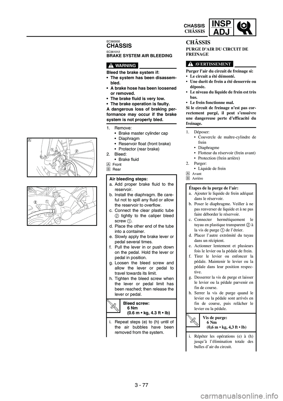
1. Remove:
Brake master cylinder cap
Diaphragm
Reservoir float (front brake)
Protector (rear brake)
2. Bleed:
Brake fluid
ÈFront
ÉRear
Air bleeding steps:
a. Add proper brake fluid to the
reservoir.
b. Install the diaphragm. Be care-
ful not to spill any fluid or allow
the reservoir to overflow.
c. Connect the clear plastic tube
2 tightly to the caliper bleed
screw
1.
d. Place the other end of the tube
into a container.
e. Slowly apply the brake lever or
pedal several times.
f. Pull the lever in or push down
on the pedal. Hold the lever or
pedal in position.
g. Loosen the bleed screw and
allow the lever or pedal to
travel towards its limit.
h. Tighten the bleed screw when
the lever or pedal limit has
been reached; then release the
lever or pedal.
T R..
Bleed screw:
6 Nm
(0.6 m kg, 4.3 ft lb)
i. Repeat steps (e) to (h) until of
the air bubbles have been
removed from the system.
È
É
CHÂSSIS
PURGE D’AIR DU CIRCUIT DE
FREINAGE
AVERTISSEMENT
Purger l’air du circuit de freinage si:
Le circuit a été démonté.
Une durit de frein a été desserrée ou
déposée.
Le niveau du liquide de frein est très
bas.
Le frein fonctionne mal.
Si le circuit de freinage n’est pas cor-
rectement purgé, il peut s’ensuivre
une dangereuse perte d’efficacité du
freinage.
1. Déposer:
Couvercle de maître-cylindre de
frein
Diaphragme
Flotteur du réservoir (frein avant)
Protection (frein arrière)
2. Purger:
Liquide de frein
È
Avant
É
Arrière
Étapes de la purge de l’air:
a. Ajouter le liquide de frein adéquat
dans le réservoir.
b. Poser le diaphragme. Veiller à ne
pas renverser de liquide et à ne pas
faire déborder le réservoir.
c. Connecter hermétiquement le
tuyau en plastique transparent 2 à
la vis de purge 1 de l’étrier.
d. Placer l’autre extrémité du tuyau
dans un récipient.
e. Actionner lentement et plusieurs
fois le levier ou la pédale de frein.
f. Tirer le levier ou enfoncer la
pédale. Maintenir le levier ou la
pédale dans leur position respec-
tive.
g. Desserrer la vis de purge et laisser
le levier ou la pédale parvenir en
fin de course.
h. Serrer la vis de purge quand le
levier ou la pédale sont arrivés en
fin de course, puis relâcher le
levier ou la pédale.
T R..
Vis de purge:
6 Nm
(0,6 m kg, 4,3 ft lb)
i. Répéter les opérations (e) à (h)
jusqu’à l’élimination totale des
bulles d’air du circuit.
CHASSIS
CHÂSSIS
Page 289 of 912
INSP
ADJ
3 - 78
FAHRWERK
HYDRAULISCHE BREMSANLAGE
ENTLÜFTEN
WARNUNG
Die Bremshydraulik in folgenden
Fällen entlüften:
Die Anlage wurde zerlegt.
Ein Bremsschlauch wurde
gelöst oder erneuert.
Der Flüssigkeitsstand ist sehr
niedrig.
Die Bremse funktioniert nicht
einwandfrei.
Eine nicht korrekt durchgeführte
Entlüftung kann die Bremsleis-
tung beeinträchtigen.
1. Demontieren:
Vorratsbehälter-Deckel
Membran
Schwimmer (Vorderradbremse)
Protektor (Hinterradbremse)
2. Ablassen:
Bremsflüssigkeit
ÈVorn
ÉHinten
Arbeitsvorgang für die Entlüf-
tung:
a. Den Vorratsbehälter mit der
empfohlenen Bremsflüssigkeit
auffüllen.
b. Die Membran einsetzen. Dar-
auf achten, dass keine Flüssig-
keit verschüttet wird und dass
der Vorratsbehälter nicht über-
läuft.
c. Einen durchsichtigen Kunst-
stoffschlauch
2 fest an der
Bremssattel-Entlüftungs-
schraube
1 anschließen.
d. Das freie Schlauchende in
einen Auffangbehälter führen.
e. Den Bremshebel mehrmals
langsam betätigen.
f. Den entsprechenden Brems-
hebel betätigen. Den Bremshe-
bel kräftig betätigen und in
dieser Stellung halten.
g. Die Entlüftungsschraube lok-
kern, woraufhin der Hebel sich
bis auf den Anschlag zubewegt.
h. Sobald der Hebel den
Anschlag erreicht hat, die Ent-
lüftungsschraube festziehen
und dann den Hebel loslassen.
T R..
Entlüftungsschraube:
6 Nm
(0,6 m kg, 4,3 ft lb)
i. Die Schritte (e) bis (h) so lange
wiederholen, bis keine Luft-
bläschen mehr im Kunststoff-
schlauch zu sehen sind.
PARTE CICLISTICA
SPURGO ARIA SISTEMA
FRENANTE
AVVERTENZA
Spurgare il circuito dei freni se:
Il sistema è stato disassemblato.
Uno dei tubi del freno è stato allen-
tato o rimosso.
Il livello del liquido freni è molto
basso.
Il funzionamento del freno è difet-
toso.
Se non si spurga correttamente il
sistema frenante, può verificarsi una
pericolosa perdita di efficienza della
frenata.
1. Togliere:
Coperchio pompa del freno
Diaframma
Galleggiante serbatoio
(freno anteriore)
Protezione (freno posteriore)
2. Spurgare:
Liquido dei freni
È
Anteriore
É
Posteriore
Operazioni per lo spurgo dell’aria:
a. Aggiungere al serbatoio il liquido
freni corretto.
b. Installare il diaframma. Atten-
zione a non versare in alcun modo
il liquido o a non far traboccare il
liquido dal serbatoio.
c. Collegare strettamente il tubo di
plastica chiaro 2 alla vite di
spurgo della pinza 1.
d. Posizionare l’altra estremità del
tubo in un recipiente.
e. Azionare lentamente la leva o il
pedale del freno diverse volte.
f. Tirare la leva o premere il pedale.
Mantenere la leva o il pedale in
posizione.
g. Allentare la vite di spurgo e por-
tare la corsa della leva o del
pedale verso il limite.
h. Avvitare la vite di spurgo quando
si raggiunge il limite della leva o
del pedale, quindi rilasciare la
leva o il pedale.
T R..
Vite di spurgo:
6 Nm
(0,6 m kg, 4,3 ft lb)
i. Ripetere le operazioni dalla (e)
alla (h) fino all’eliminazione delle
bolle d’aria dal sistema.
CHASIS
PURGA DE AIRE DEL SISTEMA
DE FRENOS
ADVERTENCIA
Debe purgar el sistema de frenos
si:
El sistema ha sido desmontado.
Se ha soltado o extraído un tubo
de freno.
El nivel de líquido de frenos está
muy bajo.
El freno funciona mal.
Si el sistema de frenos no se
purga de forma adecuada se
puede producir una peligrosa pér-
dida de rendimiento de los frenos.
1. Extraer:
Tapa de la bomba de freno
Diafragma
Flotador del depósito
(freno delantero)
Protector (freno trasero)
2. Purgar:
Líquido de frenos
ÈDelantero
ÉTrasero
Procedimiento de purga:
a. Añada líquido de frenos del
tipo adecuado al depósito.
b. Instale el diafragma. Evite
derramar líquido de frenos o
que rebose el depósito.
c. Acople firmemente el tubo de
plástico transparente
2 al tor-
nillo de purga de la pinza
1.
d. Coloque el otro extremo del
tubo en un recipiente.
e. Accione lentamente la maneta
o el pedal de freno varias
veces.
f. Apriete la maneta de freno o
pise el pedal. Mantenga la
maneta o el pedal en esa posi-
ción.
g. Afloje el tornillo de purga y deje
que la maneta o el pedal se
desplacen hasta su límite.
h. Apriete el tornillo de purga
cuando la maneta o el pedal
hayan llegado a su límite; en
ese momento suelte la maneta
o el pedal.
T R..
Tornillo de purga:
6 Nm
(0,6 m kg, 4,3 ft lb)
i. Repita los pasos (e) a (h) hasta
eliminar las burbujas de aire
del sistema.
FAHRWERK
PARTE CICLISTICA
CHASIS
Page 290 of 912
3 - 79
INSP
ADJ
3. Install:
Protector (rear brake)
Reservoir float (front brake)
Diaphragm
Brake master cylinder cap
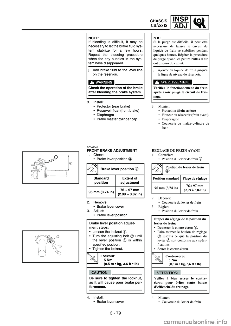
EC362040FRONT BRAKE ADJUSTMENT
1. Check:
Brake lever position
a
2. Remove:
Brake lever cover
3. Adjust:
Brake lever position
4. Install:
Brake lever cover
NOTE:If bleeding is difficult, it may be
necessary to let the brake fluid sys-
tem stabilize for a few hours.
Repeat the bleeding procedure
when the tiny bubbles in the sys-
tem have disappeared.
j. Add brake fluid to the level line
on the reservoir.
WARNING
Check the operation of the brake
after bleeding the brake system.
Brake lever position a:
Standard
positionExtent of
adjustment
95 mm (3.74 in)76 ~ 97 mm
(2.99 ~ 3.82 in)
Brake lever position adjust-
ment steps:
Loosen the locknut
1.
Turn the adjusting bolt
2 until
the lever position
a is within
specified position.
Tighten the locknut.
T R..
Locknut:
5 Nm
(0.5 m kg, 3.6 ft lb)
CAUTION:
Be sure to tighten the locknut,
as it will cause poor brake per-
formance.
3. Monter:
Protection (frein arrière)
Flotteur du réservoir (frein avant)
Diaphragme
Couvercle de maître-cylindre de
frein
REGLAGE DU FREIN AVANT
1. Contrôler:
Position du levier de frein a
2. Déposer:
Couvercle du levier de frein
3. Régler:
Position du levier de frein
4. Monter:
Couvercle du levier de frein
N.B.:
Si la purge est difficile, il peut être
nécessaire de laisser le circuit du
liquide de frein se stabiliser pendant
quelques heures. Répéter la procédure
de purge quand les petites bulles d’air
ont disparu du circuit.
j. Ajouter du liquide de frein jusqu’à
la ligne de niveau du réservoir.
AVERTISSEMENT
Vérifier le fonctionnement du frein
après avoir purgé le circuit de frei-
nage.
Position du levier de frein
a:
Position standard Plage de réglage
95 mm (3,74 in)76 à 97 mm
(2,99 à 3,82 in)
Etapes du réglage de la position du
levier de frein:
Desserrer le contre-écrou 1.
Faire tourner le boulon de réglage
2 jusqu’à ce que la position du
levier a soit conforme aux spéci-
fications.
Serrer le contre-écrou.
T R..
Contre-écrou:
5 Nm
(0,5 m kg, 3,6 ft lb)
ATTENTION:
Veiller à bien serrer le contre-
écrou pour éviter toute baisse
d’efficacité du freinage.
CHASSIS
CHÂSSIS